Objective:
Design a CNC machine
My Tasks:
- Design the the X-axis for the machine in Fusion 360- Manufacturing the parts
- Electronics, wiring and programming setup
- Assembly of X-axis
Group Work
Design the the X-axis for the machine in Fusion 360
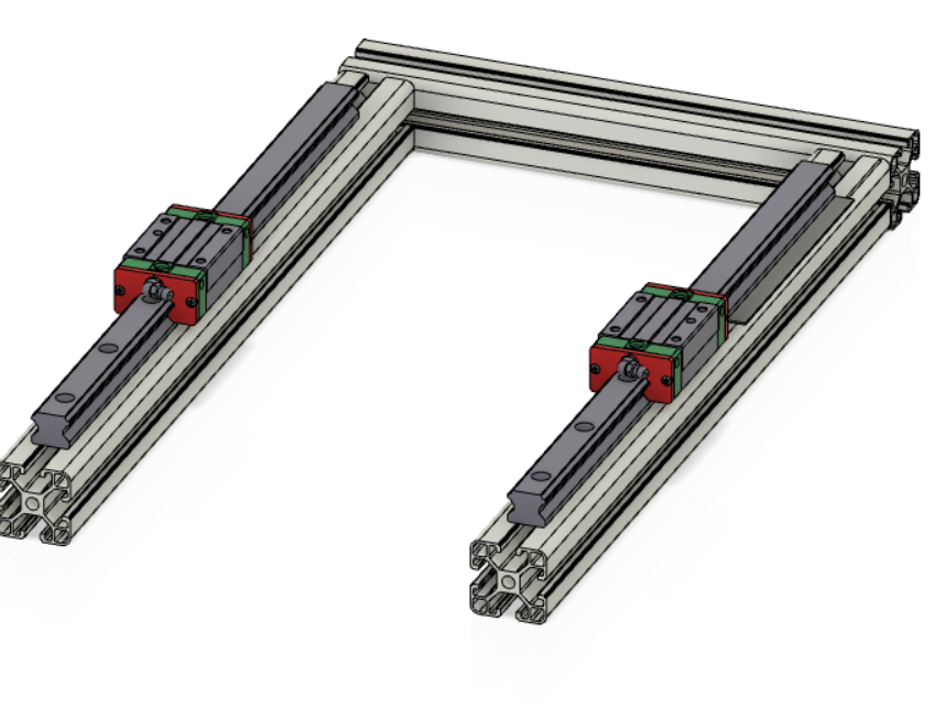
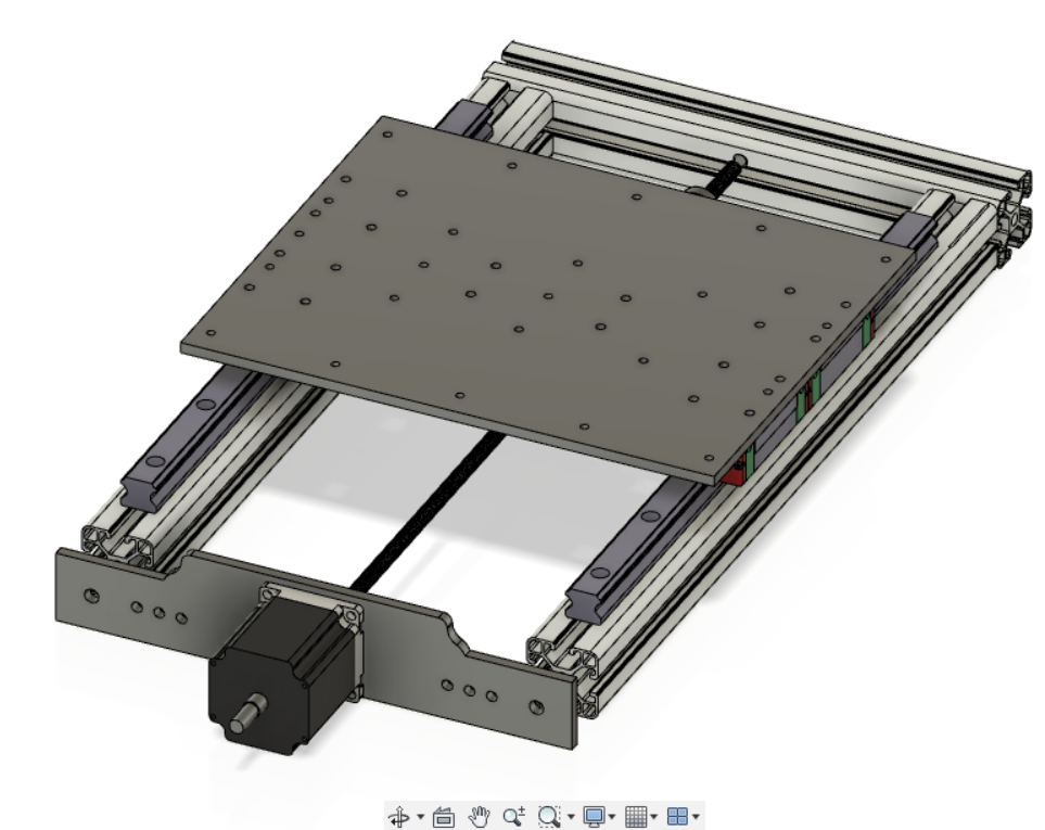
First we started by gathering the digital Components of our design from Grabcad.com which contains a huge library of many parts. after that we started to combine the frame of the design, we are using 40X40 Aluminum extrusions as a base frame, which will have linear rails installed on them like this
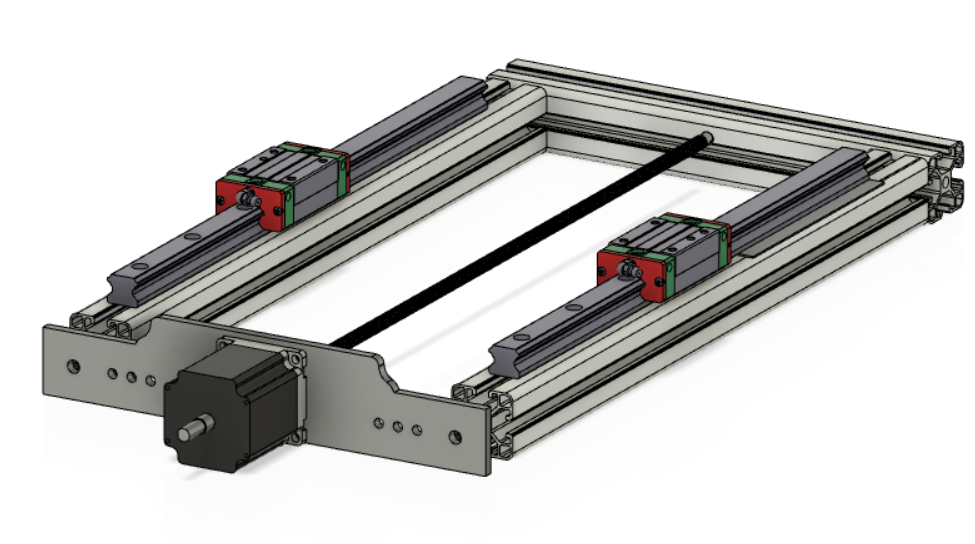
To install the motor i needed to design a part(X-axis motor mount) that would hold the Stepper motor with aluminum extrusions.
After that, I had to design a part(X-axis plate mount) that would attached to lead screw so it moves when motor in turning. holes are added on the top to connect to the base plate afterwards.
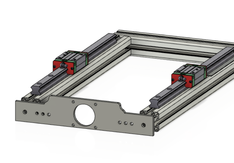
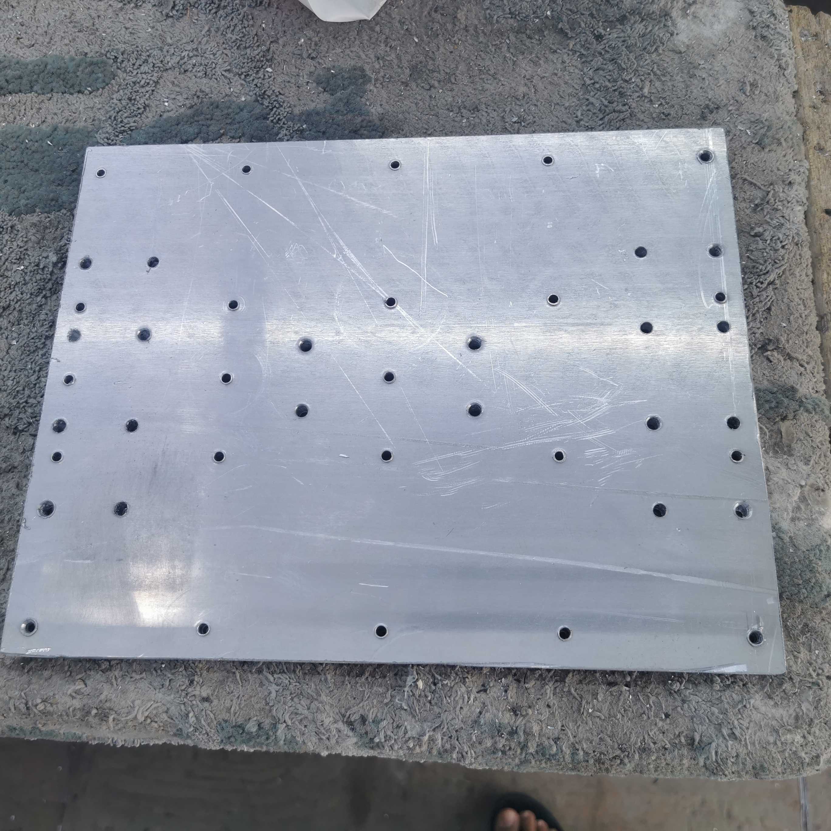
Then i designed the base plate, which will hold the material that would be cut by the spindle of the machine, the plate has 3 kinds holes.
1 - To connect the plate with the Rails
2 - To connect the plate with mount on lead screw
3 - To connect the plate with sacrificial layer
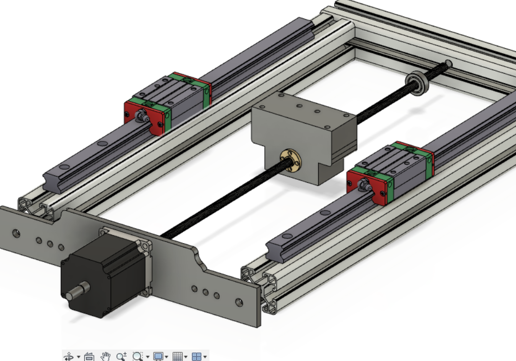
Now the Design of the X-axis is almost ready, only few parts remaining, one part to hold the lead screw in place and one part to hold the end-stop switches.
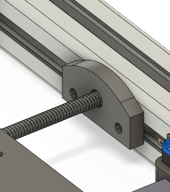
To hold the Lead screw in place i designed this simple part that would include a bearing so it dosen't constrain the movement of the lead screw.
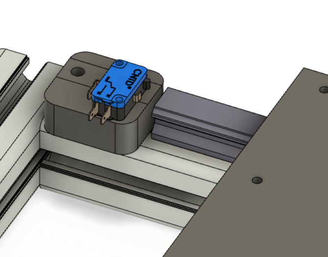
And the last part would be the End stop switch holder.
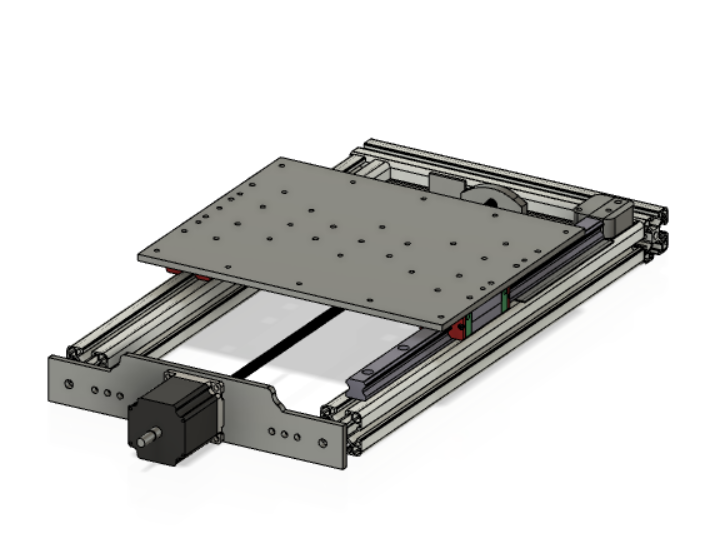
X-axis Final look
Manufacturing the parts
Some of the parts we manufactured in the lab using Machines we were trained on such CNC machine(Shopbot), Laser Cutters and 3D printers.
Manufacturing of X-axis motor mount was done using an aluminum plate that was cut by the shopbot.
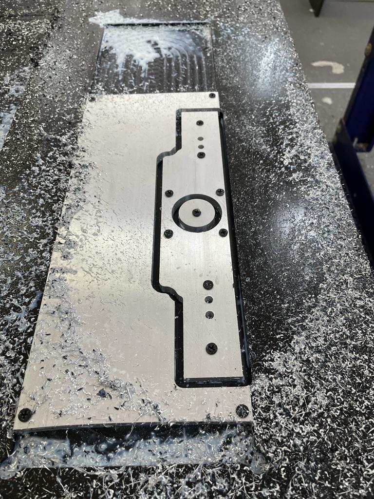
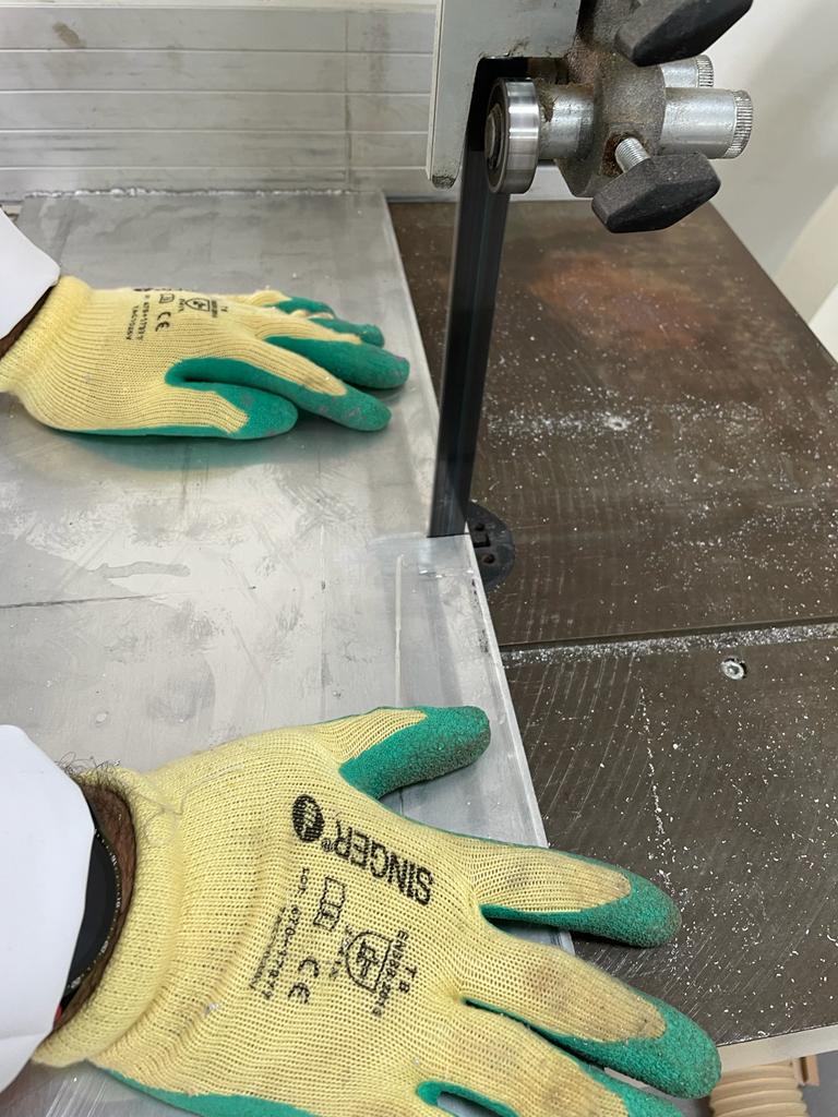
Manufacturing of X-axis Plate using the saw machine, to cut a piece of aluminum, and then use the CNC machine to cut for the holes.
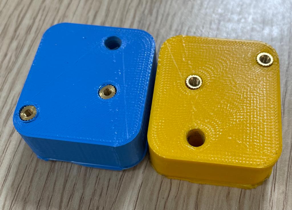
3D Printing of the end stop switch holder
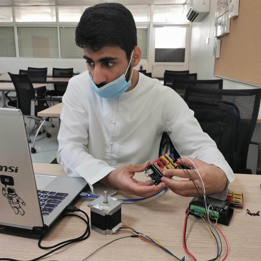
Electronics, wiring and programming setup
I was responsible of the electronics as well, for the electronics, we used arduino uno and we used the GRBL shield to connect the motors to it.
First I installed the GRBL library onto the arduino by following this Link
Then I followed the manufacturer of the motor drivers on the wiring Here.
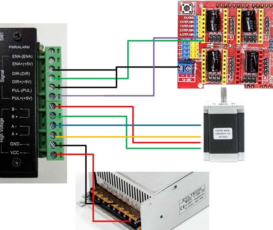
Then I continued with the wiring and checked if the motors work.
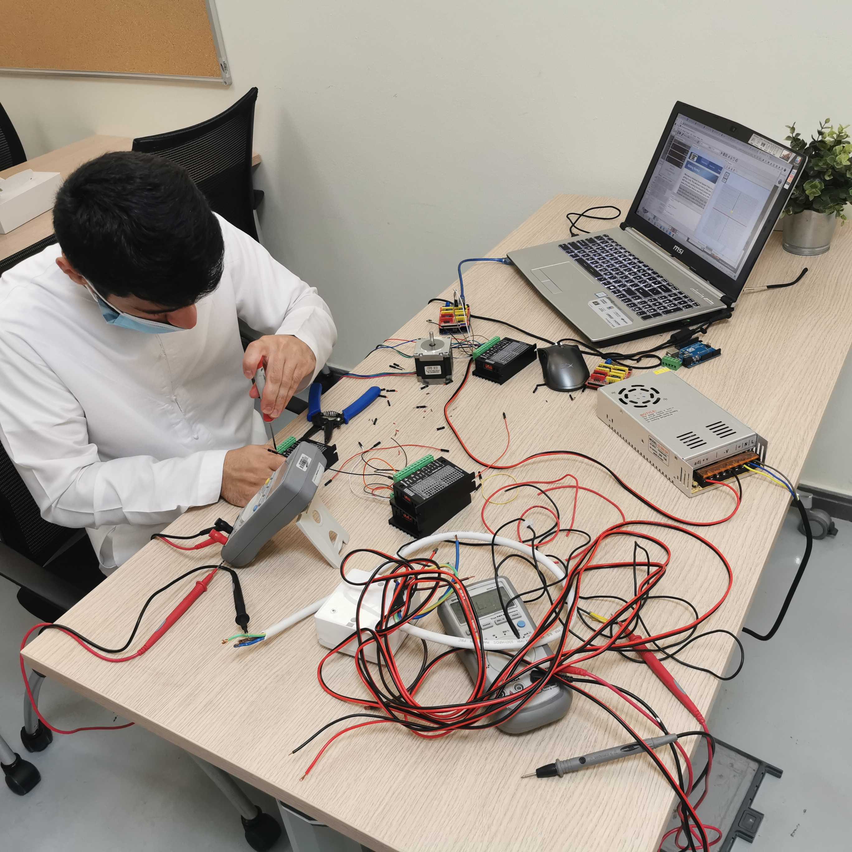
After I checked all the motors work, This has been done using one of many tools which is a Gcode sender that is used to control the GRBL based systems, I used the Universal GCODE sender platform Its quite simple and easy to use and there are tutorials online on how to use it. I followed these tutorials for the setup and how to use the software.
1
2
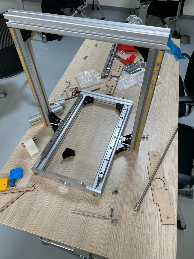
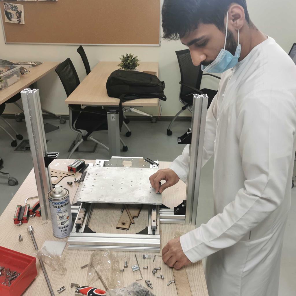
X-Axis Assembly
One of the tasks took most of the time is the act of assembling, tighting, untighting and unassembling again these are all due to trial and error and lack of precsion from our side. Here are few pictures of the X-axis assembly
After the Assembly it's time for the Manual testing of the X-axis
Then, Time for the X-axis test with the Motors
