Final Project
The time has come, the time to choose the final project. As I have already mentioned in the first assignment, I will bring a project concerning healthcare design. The idea consists in designing several objects (a kind of kit) that can help, or at least facilitate, actions of daily life for people suffering from quadriplagia and paraplegia. Each object will be designed with different techniques and machinery, with the intention of practicing and learning the way they work at 360°. I know that I will probably make this journey even more troubled and complex, especially since the only project I did in this field was for my degree thesis. Despite this, I prefer having to work harder, and perhaps even more time, knowing that I am satisfied with my final work and that I can say that I gave it all.
The programs that I will use for the project are: illustrator, for sketches, drawings and various graphics; autocad, for the 2D of the projects; and finally fusion 360 and blender for 3D modeling. I chose to use Fusion 360 because it is one of the three-dimensional modeling programs that I know less, and since it is parametric design it will help me to make inclusive projects easily customizable.
People suffering from paraplegia and quadriplegia have difficulty in many daily actions that go beyond just walking, such as washing, dressing, eating, driving, cooking, not to mention architectural barriers inside and outside the home. Many of them find tricks to adapt everyday objects to their needs, for example they customize their pants with velcro, to make the action of dressing/undressing easier for them and their caregiver, or they create some knobs to handle brushes for make-up or even cutlery to eat independently. Such creativity should be exploited! The risk that can occur in designing objects for people with disabilities is that the latter feel “different”, as if they needed special objects designed for them and only them. This is not the case, on the contrary, the purpose of this project will be to create devices suitable for everyone and totally inclusive, and to make them inclusive we must obviously also take into account those who have movement difficulties or cognitive difficulties etc. In order to do this, there is a need for a confrontation with several people, who are victims of their lives every day, when the reality is that we all deserve to be the main characters of our life, because a person is not his/her illness.
Research
The starting point will be the project that I brought into thesis, with the intention of improving it or even evolving it into something new. Manobo is a device for the rehabilitation of the hand, born thanks to the collaboration of physiotherapists, essential for the technical and scientific part, and of the fablab Opendot, who helped me in the realization of the model. This work has various objectives, which go beyond the function of the object. The first is the desire to make the world of Design For All known, therefore a design that is first of all inclusive and not “niche” like the one we are used to every day.
The purpose of the DfA was to answer the following question:
If objects are used by people, and people are all different, both physically and psychologically; how can the designer find a single solution that can meet different needs for different people? And from the moment in which within the user there are groups that, numerically, are in the minority, and that can be divided into further subgroups being diversified by needs, measures and capacities: how can the designer develop solutions that adapt at the same time to the more users?
The answer can be found in the 7 principles that a DfA project must follow at the same time.
-
Fair use: A project must have the fewest differences between users with different abilities.
-
Flexible use: a project must adapt as much as possible to a wide range of abilities and disabilities.
-
Simple and intuitive use: the interaction between device and user must in fact be simple and intuitive, as the device must refer to a conceptual model already known and memorized by the user, in order to make it familiar and close to his acquaintances.
-
Perceptibility of information: the communication of information must be comprehensive and take place regardless of the environmental context or the user’s sensory perception skills.
-
Error tolerance: the project must be designed to minimize risks, accidental actions and any errors.
-
Containment of physical effort: the user of the project must be able to use it effectively with minimum effort, also considering the maintenance of a physiological body position.
-
Measures and spaces for approach and use: the elements that make up the device must be clearly visible and easily reachable, whether the user is seated or in an upright position. There must also be variations in the size of the hand and the size of the grip, and the presence of adequate space to allow the user who needs it to make use of personal assistance or auxiliary systems.
The second objective lies in the collaboration and co-planning with people from different fields, since only by combining one’s knowledge can lead to new ideas. All this was done following the points of the “Manifesto of Co-design for health and care”, written by OpenDot.
-
Listening and observing: Co-designing means creating a space where all opinions, skills and experiences count and serve
-
Teach and learn: We are all experts in something and mutual training is essential
-
Speaking the same language: Breaking down the wall of English and specialized terminology in favor of a common language understandable by all.
-
Sharing the real need: The goal is to solve a real need, small or large, it does not matter, what matters is to focus on why, how comes later.
-
Thinking and planning together: Moments of sharing, exchange and collective planning guide the group towards the final idea, stimulating everyone’s creativity in thinking of new and innovative solutions capable of responding to real needs.
-
Materialize the idea: The production of a first prototype allows, thanks to software, digital manufacturing technologies and rapid prototyping, to touch, explore, test the idea. And, last but not least, personalize it.
-
Prototype, prototype: The prototyping phase is a spiral process: projects improve with increasing versions, in the face of constant dialogue on how to perfect the object.
-
Replicate, scale, share: An object well designed on the single can be useful and replicated to meet the needs of others. Here the value and philosophy of open source comes into play: sharing the process and the final solution is a way to enrich the project and expand its social impact.
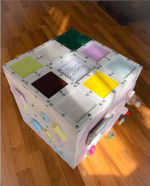
The third and last objective coincides with the functionality of the product itself, therefore the design of an object with extensive functionality to satisfy a vast target, which we will now go to describe in detail.
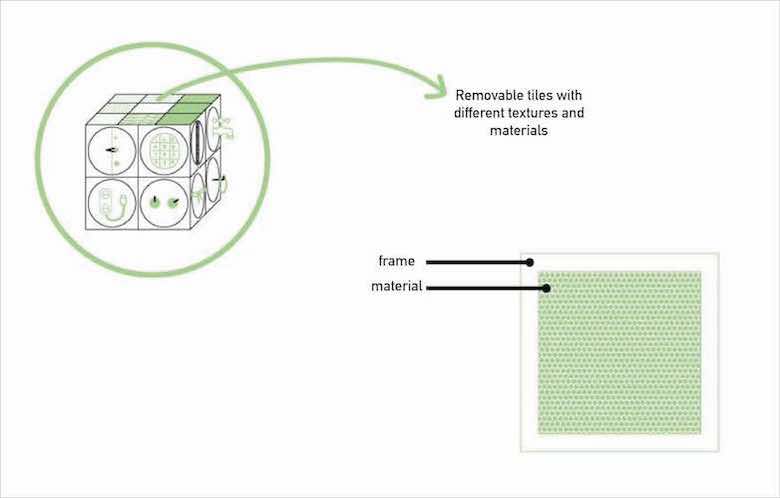
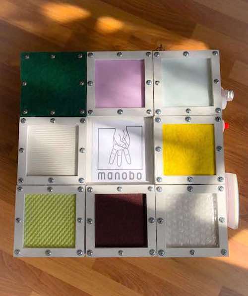
The upper face has 8 wooden tiles (12x12 cm), covered with eight different materials to train the user to restore the surface tactile sensitivity of the hand. The tiles are removable as they are joined to the base by magnets, to allow the patient to hold the object in his own hands and thus be able to analyze it better. Furthermore, thanks to the “offset” frame of the card, it is possible to change the material, as it will be enough to unscrew and screw the small 8 screws that join the two elements together.
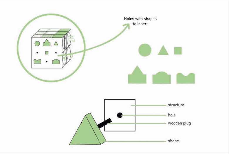
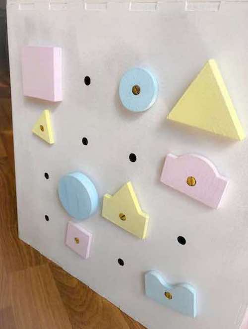
The front face has holes, in which the user can practice by inserting special shapes, thus working on precision and grips. Furthermore, the shapes can also be used as an exercise on sensitivity, the purpose of which will be to recognize squares, triangles and circles of different sizes, and the mountain-sea-hill difference, a very common exercise in the departments of rehabilitation.
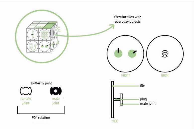
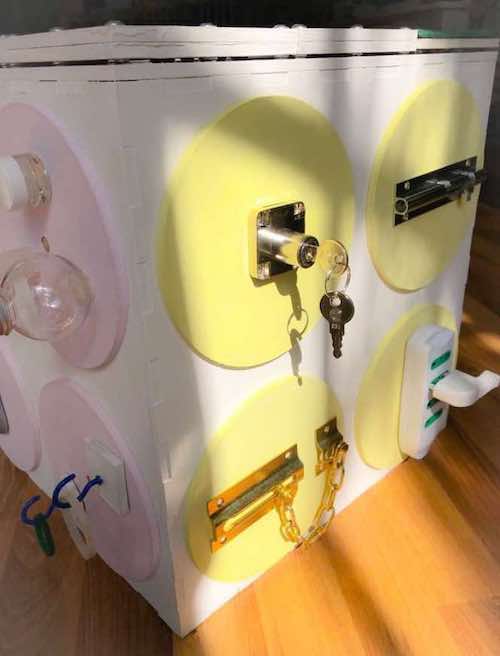
The other side faces are dedicated to objects of daily life, to better simulate the difficulties of a patient in performing daily actions. Each object will rest on a circular tile, which can be removed and put back very easily through a simple joint. The fact that the objects are removable allows you to customize the product for each user who, under the supervision of a specialist, will create his own Manobo. Subsequently, this will also lead to the creation of more and more tiles, drastically lowering costs and making it also economically inclusive. Some examples of tiles are: a tap (thumb-digital grip) and a electrical socket, which requires a certain type of precision to center the holes, and a minimum of force to extract it. Or a key lock and a latch, both of which have precision grips when inserting the key and bolt of the lock, and force for the insertion and extraction action. While grip exercises include shirt buttons, clip buttons and hook buttons, which train the multi-digital grip.
The material used for the basic structure is MDF (Medium Density Fiberboard). MDF is made with wood fibers pressed together with resin or glue at high temperatures, thus producing a very resistant material. This compound is then coated with a patina to give a smooth finish. As the name suggests, we find it in the form of panels which, as in the case of Manobo, have been cut using a Laser Cutter, that is a type of CNC (Computer Numerical Controlled) machine, which uses laser optics to cut various types of materials: from plexiglass to wood, from felt to leather. Digitally controlled optics direct a laser at high power on the cutting line, allowing for extreme speed and precision. Ideal for the production of prototypes, design objects, decorations, jewelry and more. Assembly is achieved thanks to to the use of glue, screws and stamps and magnets. The “external” elements, those positioned on the tiles, are all pre-existing and chosen by the user and their caregiver/doctor. Manobo is a totally inclusive device, which reflects the requirements of Design for all, despite this it requires medical support to be used correctly and safely. Consequently, the purchase target is identifiable in hospitals or clinics, while that of use in patients, who can use them under the supervision of a competent figure, who has the possibility to create an ad hoc version of Manobo for each user. Through the exchange of materials, cards and faces, the user will have a tool that can be fully customized according to his needs.
Planning
Since bringing this project to life I was excited, I decided to stay in this field for the final FabAcademy project. For this reason my instructor Antonio and I have made an appointment at the Niguarda hospital in Milan, to talk about a possible collaboration with the spinal unit department. I am here today to tell you that…drum roll…they have made themselves available for any questions, both with patients and healthcare professionals!! The next step will be to brainstorm possible devices to design, propose them and understand together which ones to prototype (genuinely screaming inside).
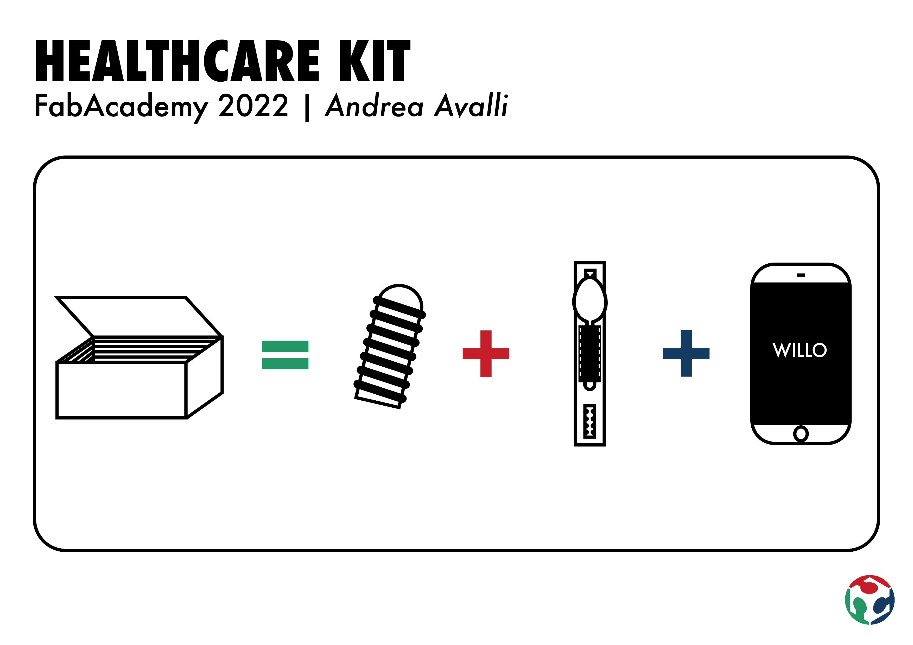
After talking about it with my instructor, we came to the conclusion of creating a kit with three objects intended for patients with paraplegia and quadriplegia.
Unfortunately time is short and to collaborate with an institution such as a hospital you need a lot of documents and bureaucracies. For this reason (spoiler alert) we were able to go to the hospital only once, but after the end of the FabAcademy I would like to contact them for a collaboration.
DEETO
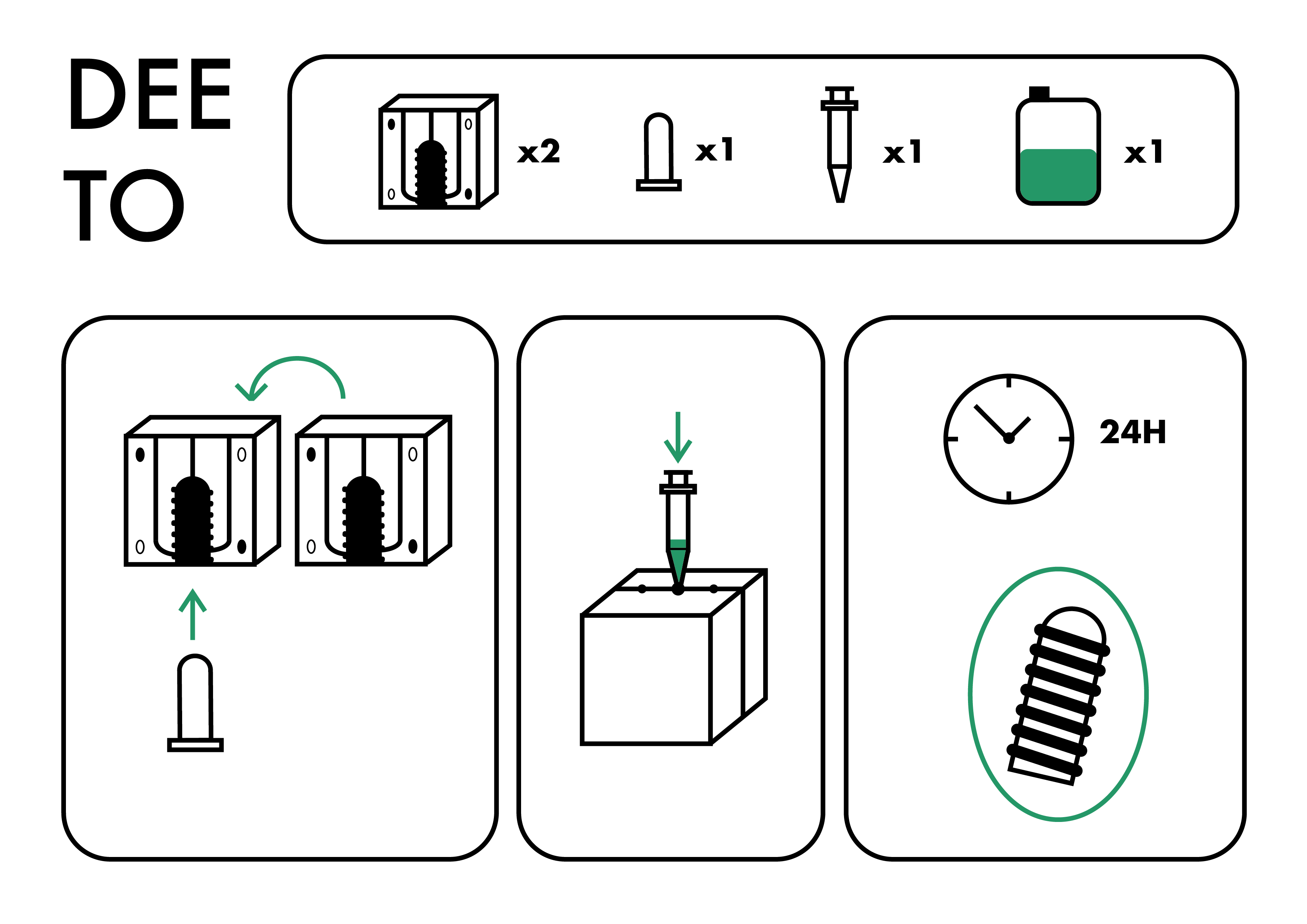
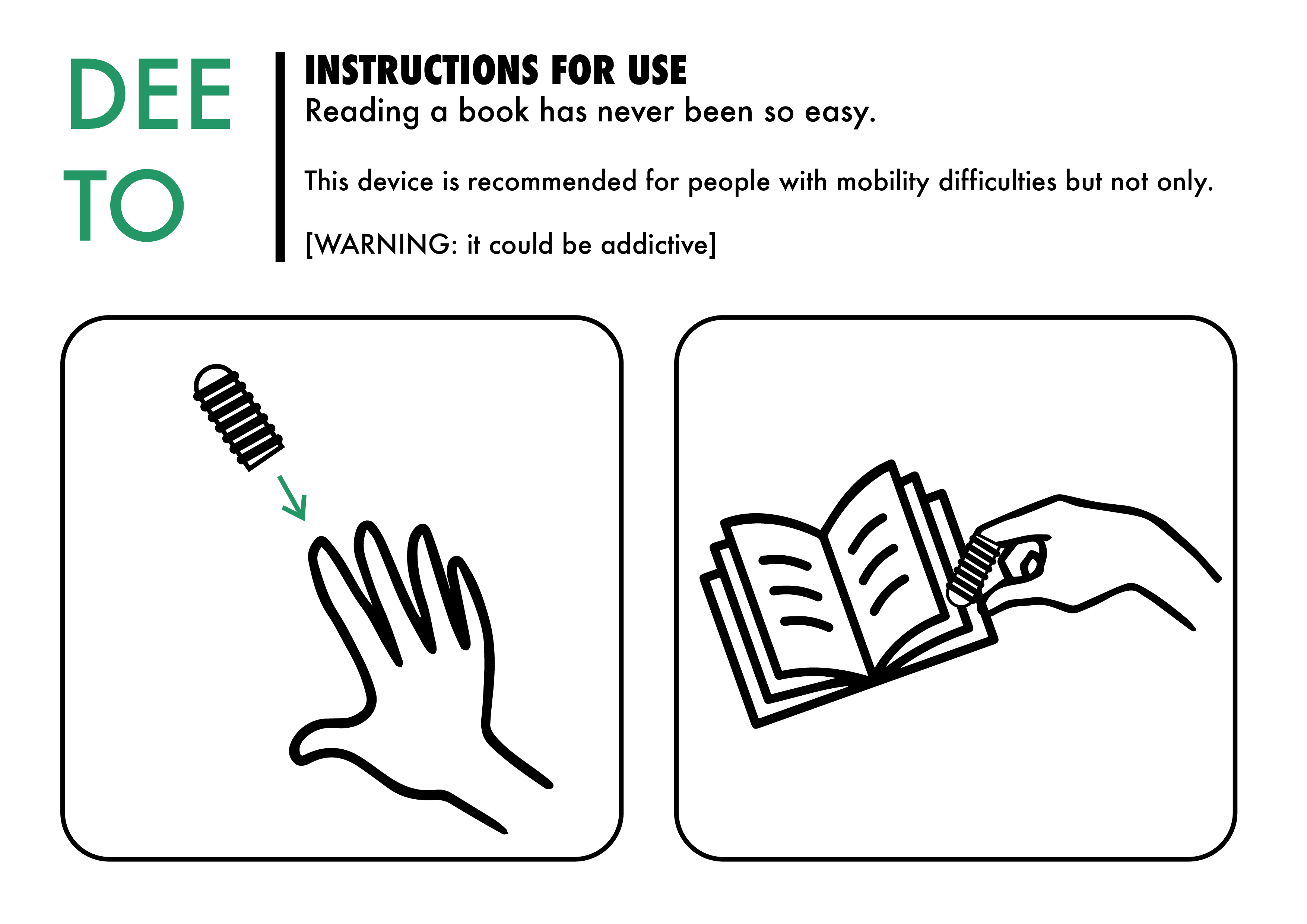
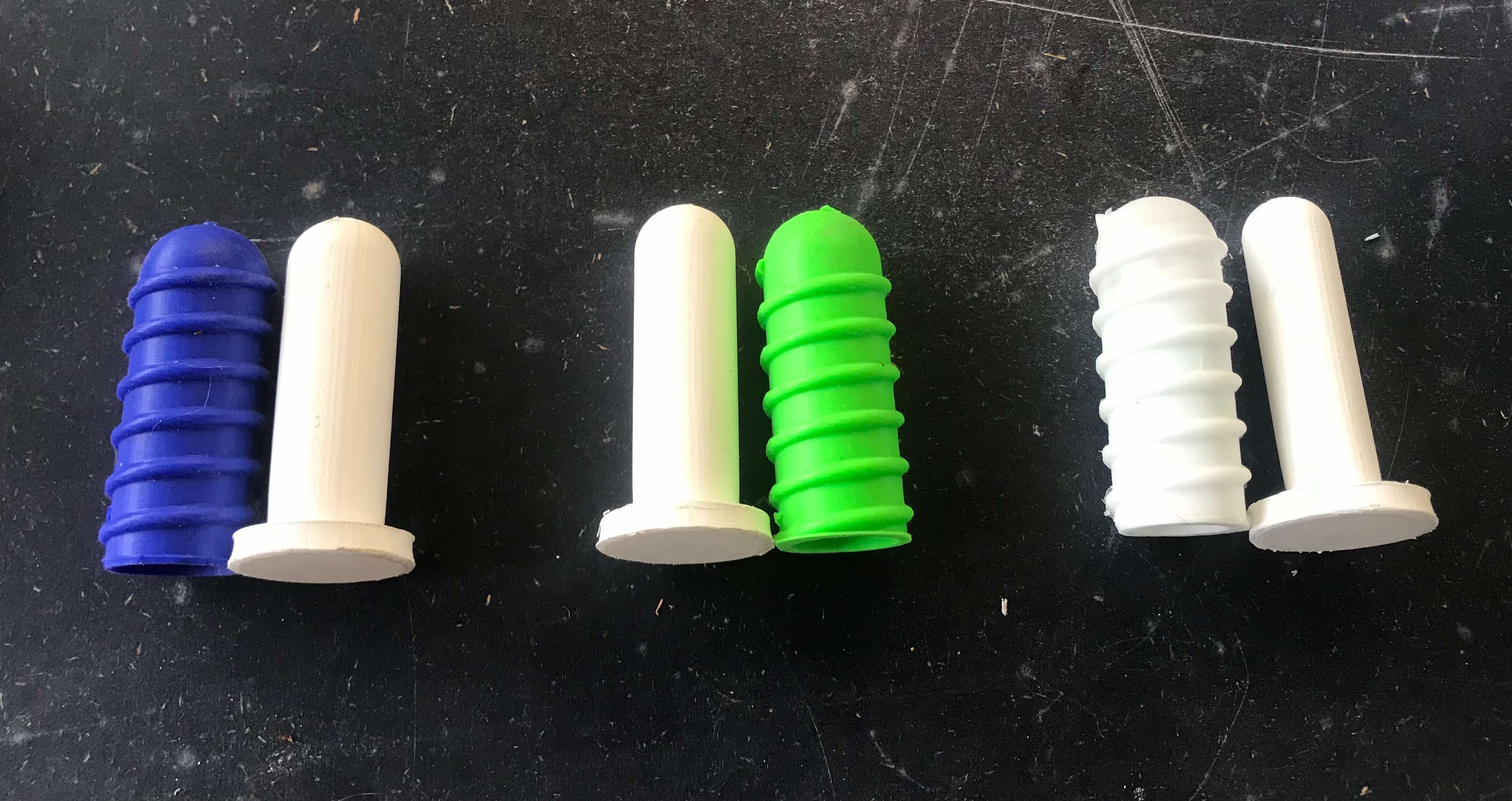
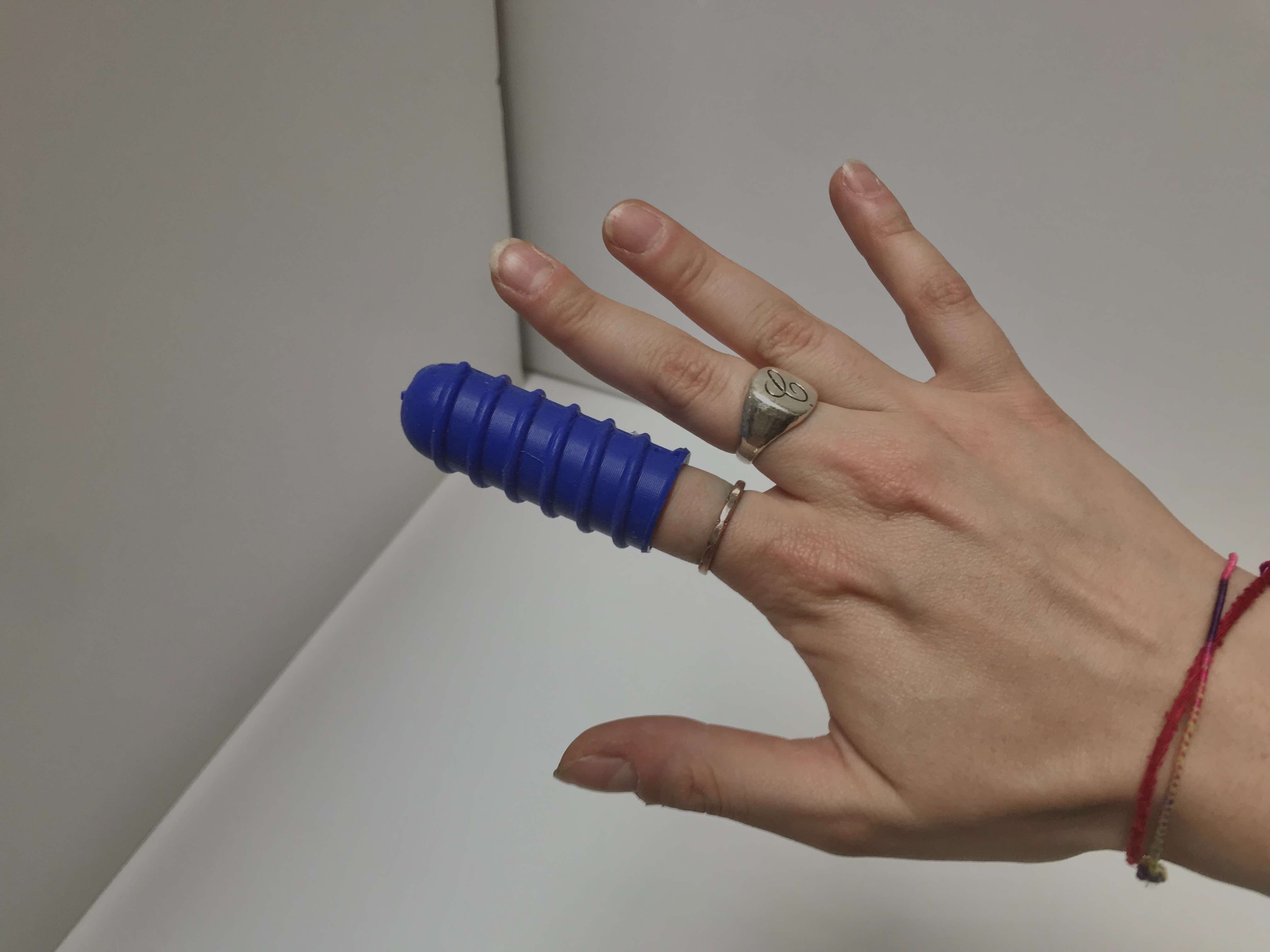
The first object will be DEETO, a rubber thimble with a pattern that creates friction, intended for people who have no motor skills, to help them turn the pages of a book or for example a newspaper. To create it we will need a wax mold made of two parts and a 3D printed part that will be used to create the hole to insert the finger. Thanks to this last part we will be able to obtain thimbles of different diameters, as it will be enough to print several pieces of different sizes to obtain a larger or smaller hole.
The steps to do this are the following:
-
CAD model: parametric modeling of the final product on Fusion 360
-
Mold CAD: parametric modeling of the wax mold on Fusion 360 + parametric modeling of the internal mold on Fusion 360
-
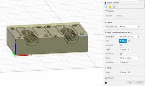
Mold milling: manufacturing on Fusion 360 (to choose the tips and set the path of the machine) + create machine gcodes + mill everything with a Shopbot
-
3D printing: printing the internal mold using an Ultimaker
-
Casting: choose the optimal material for the final product and pour it into the mold + wait for it to dry
-
Experimentation: let one/more patients try the final product
BANGO
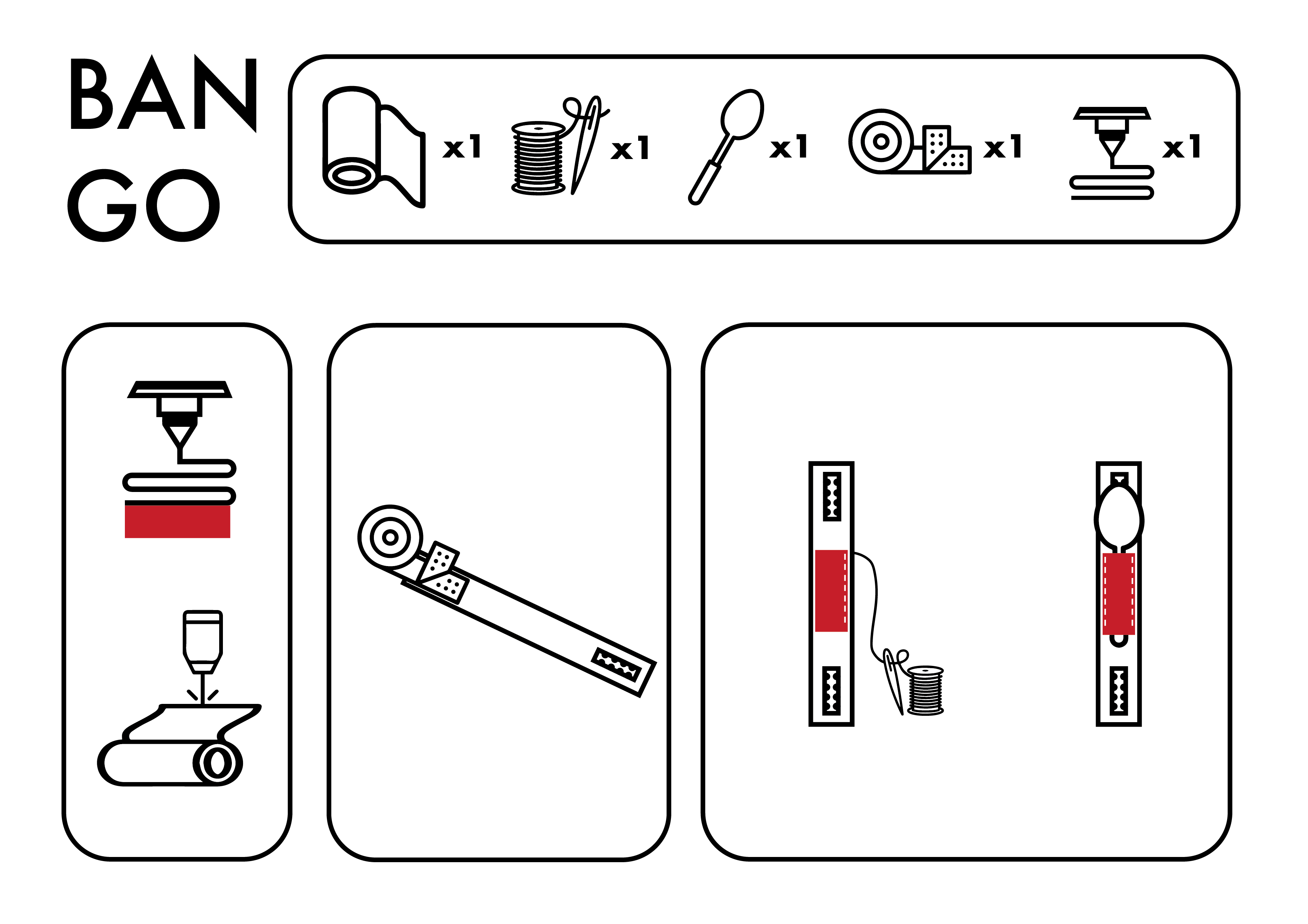
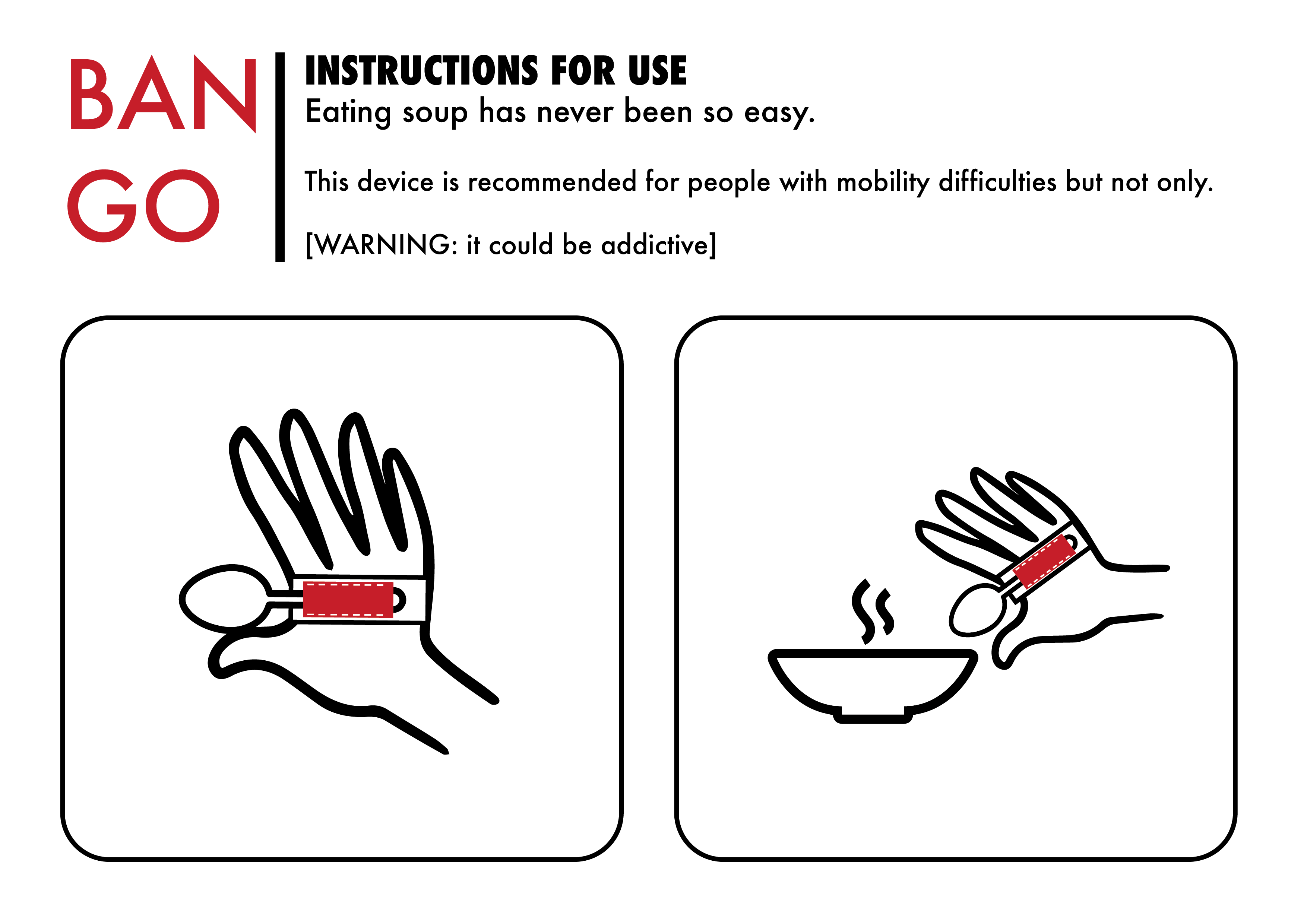
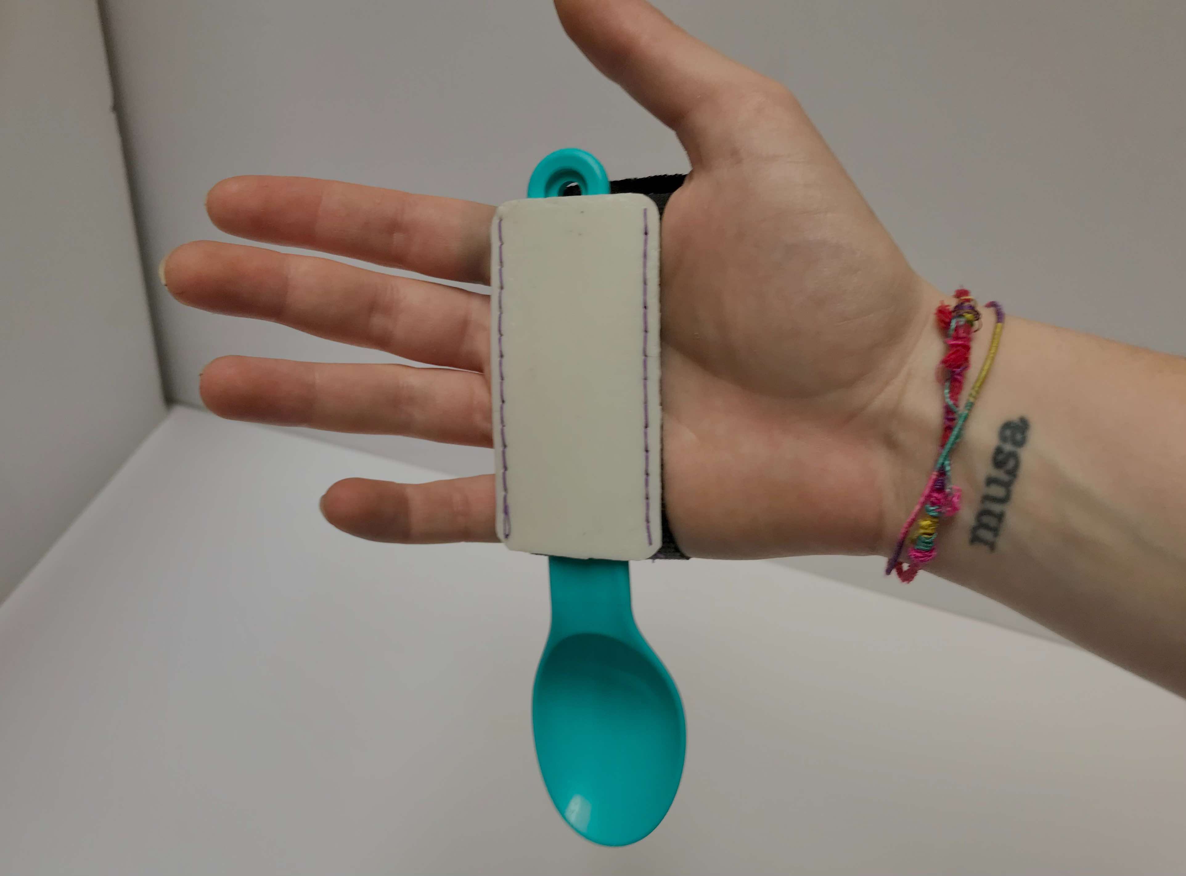
The second object will be BANGO, a sort of hand-bracelet equipped to help people with little hand control to eat independently. A fork or spoon can be attached to the palm as needed, and the patient, if equipped with minimal biceps mobility, will be able to feed independently.
Below we find the steps to follow for the realization of this product:
-
CAD model: parametric modeling of the bracelet and of the pocket to insert the cutlery
-
3d printing: pocket in TPU
-
Sewing: the velcro and the pocket to the fabric
-
Experimentation: let one/more patients try the final product
WILLO
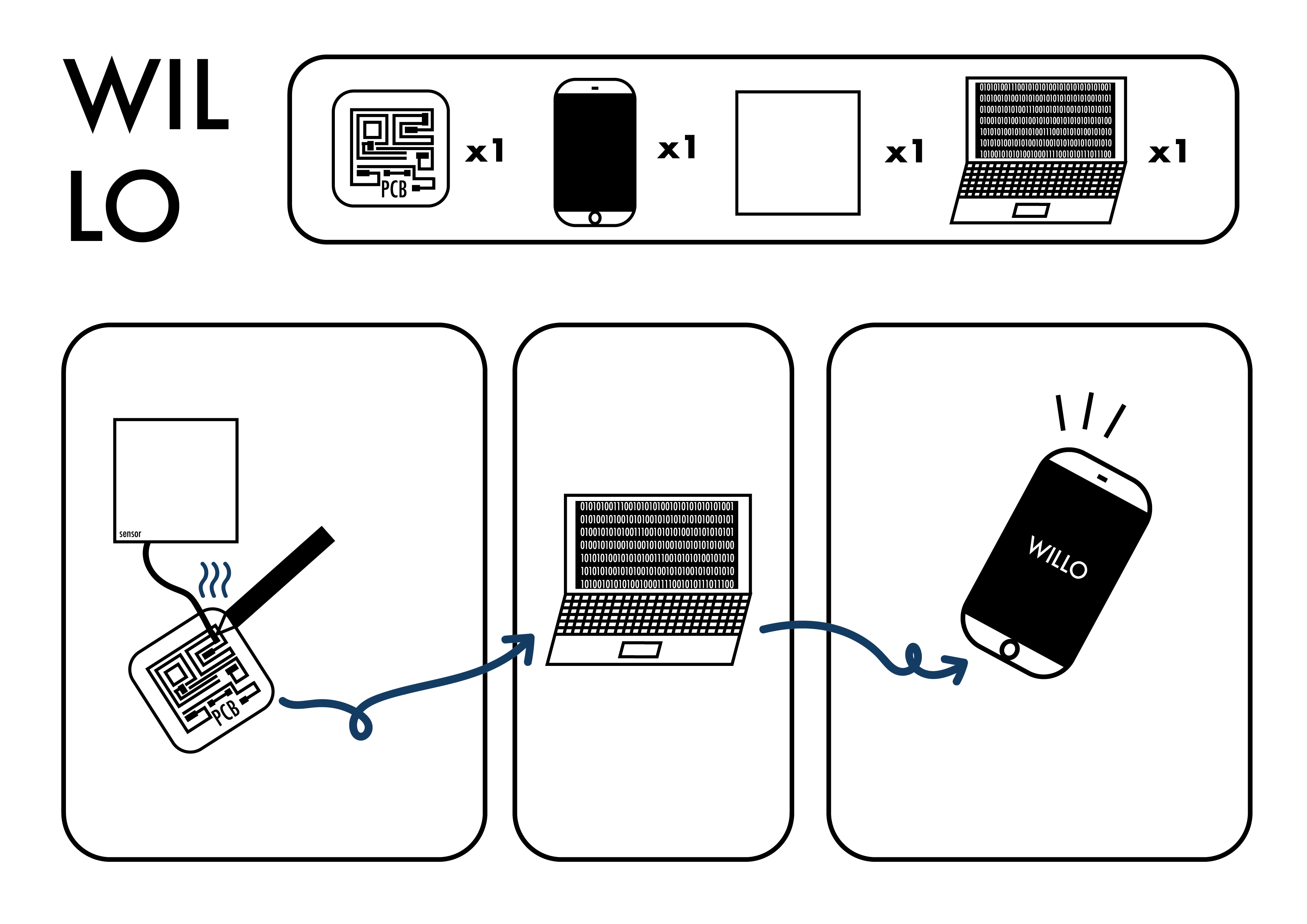
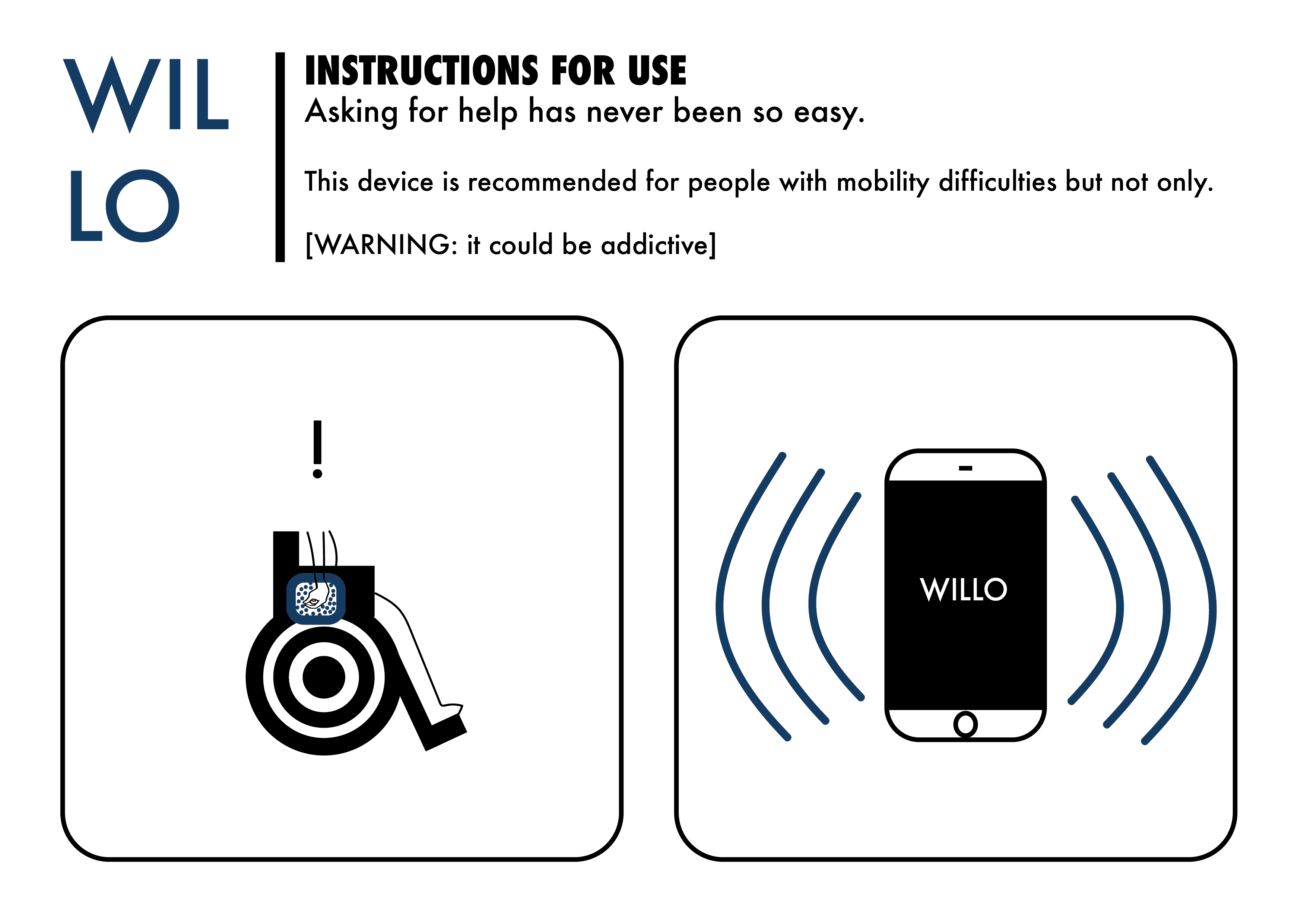
The third object is WILLO, a device that, through a special sensor, will help the patient in emergencies, in fact the patient can ask for help by simply bringing his arm close to the device, without having to press any button. Thanks to this device, patients can be more independent and, in an emergency, a small movement of the arm will be enough. It is especially designed for those who are not in control of their hands, for whom even pressing a button can be difficult. As soon as the sensor is “activated”, the device will send a notification to the doctor/caregiver using an app.
This object is a bit more complex than the others, so let’s see the steps to follow:
-
E-CAD: designing a compact board that can contain all the components we need
-
PCB milling: mill the PCB using a Roland
-
Soldering: solder all the components to our board
-
Input: capacitive sensor
-
Output: LED RGB
-
Network: create communication via wifi to another device
-
Interface: create an app where you can receive alerts
-
Experimentation: let one/more patients try the final product
All these items will be placed in a box designed for this project.
Deeto
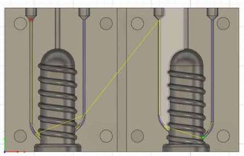
Let’s start from the CAD of our thimble. Open Fusion 360 and make a new sketch. We will start by doing the 3D model of the final project to make the mold.
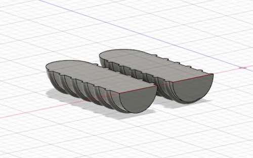
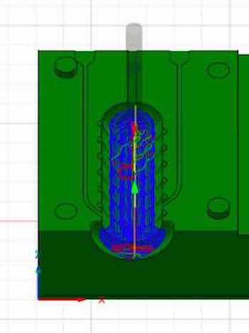
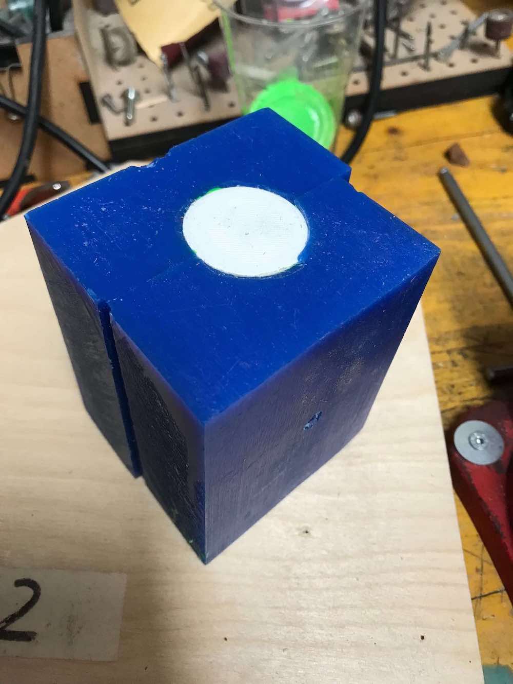
Subsequently, by taking the measurements of our stock (I will use a wax brick) we can begin to shape the mold. It will also need joints, to ensure that they do not separate during casting, and channels for the entry of the material and the exit of air.
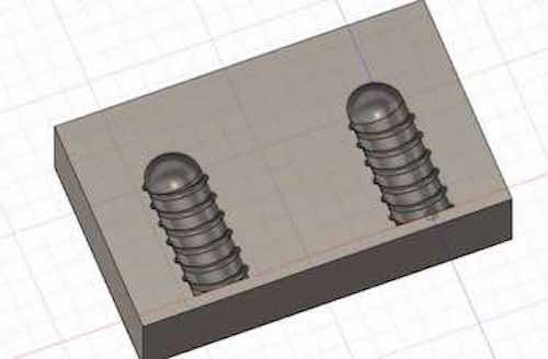
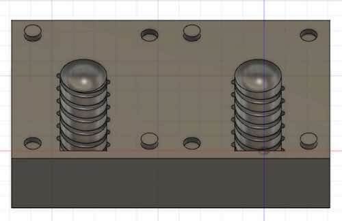
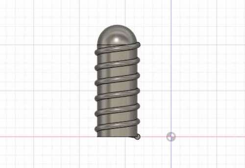
I also added a central groove to make it easier to cut the mold with the circular saw, and some small grooves to fit the internal molds that we can see below.
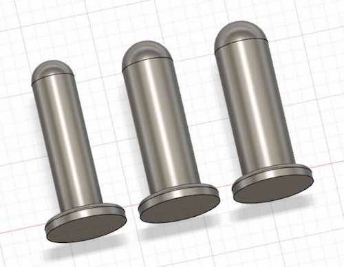
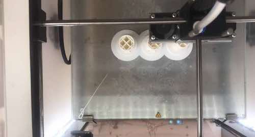
Through the “revolution” command I have created three different models, which we will print with an ultimaker. They will be used to leave space for a finger inside the mold. This is the most customizable part of the project, as by changing the diameter of it, you can get different measures, which is why I made three for demonstration purposes.
While we send the three fingers to print, which we have previously exported in stl, we move on to the manufacture part of the mold.
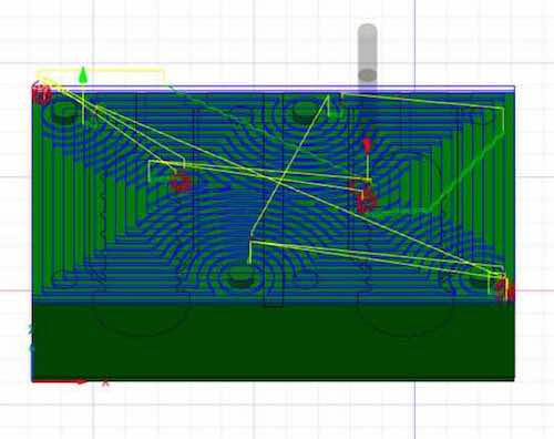
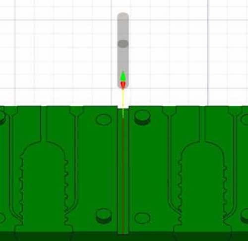
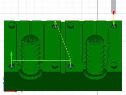
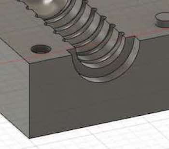
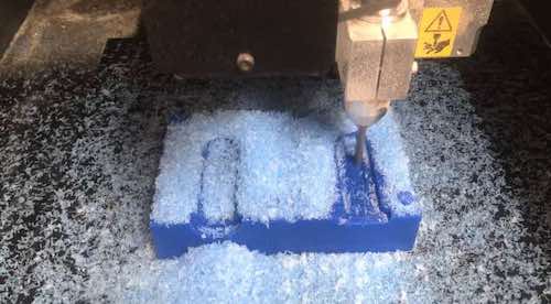
Using a 6 mm flat tip we will do 4 pocket processing, which we will need to dig out the superfluous material and create grooves.
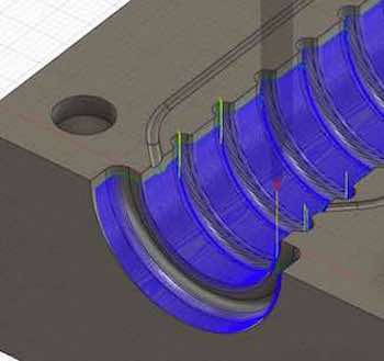
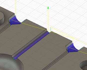
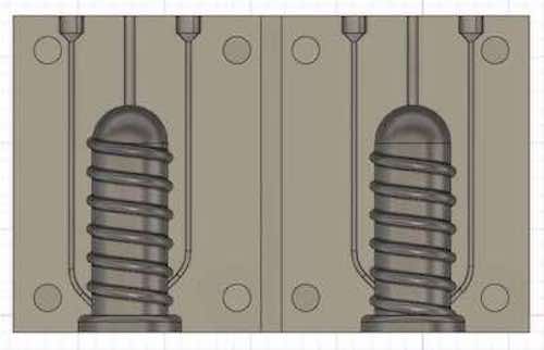
While using a 1.5 mm tip we are going to do the final touches: the passage channels and the internal spiral around the mold.
Here’s a sneak peek while printing and milling:
Now that we’re done with the molding part, we can start the casting part. What we need is the wax mold, the printed mold and rubbery material, like sintagom or .
Once we fit together the 3-parts-mold, to make sure everything is sealed well, we will add clamps on all four sides (warning: since wax is an extremely fragile material, I recommend using pieces of waste material, such as wood or cardboard, to prevent the clamp to ruin the wax).
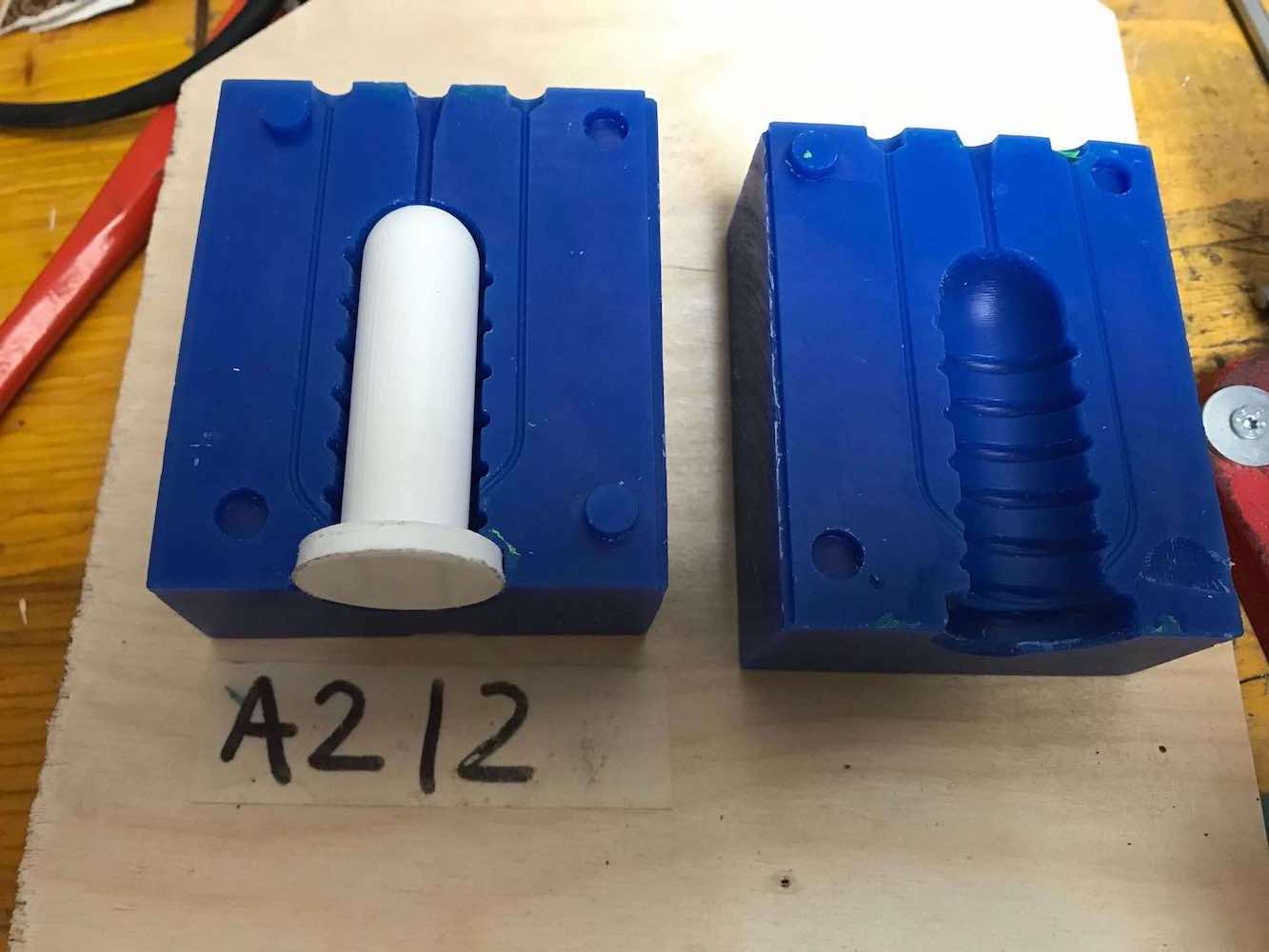
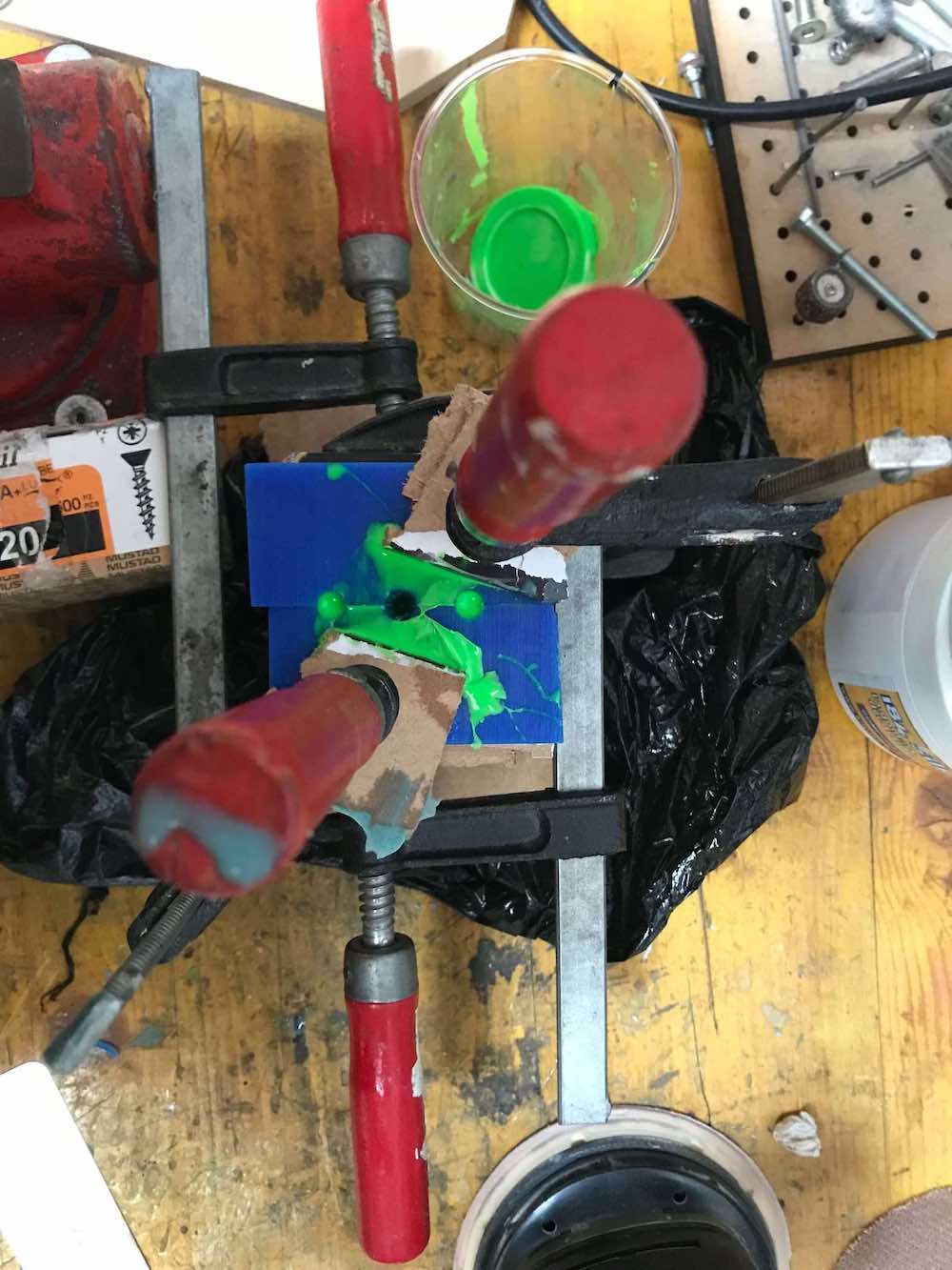
The material we’re going to use for the casting is Silplay 184/30, which is a two-component silicone rubber. This product, after the union of the two components, vulcanizes at room temperature without the need to be baked in the oven and without other precautions. To add a pop of color I simply added a pinch of green pigment to component A, before mixing it with the catalyst.
After 24-48h of waiting, we can remove the clamps and see the result.
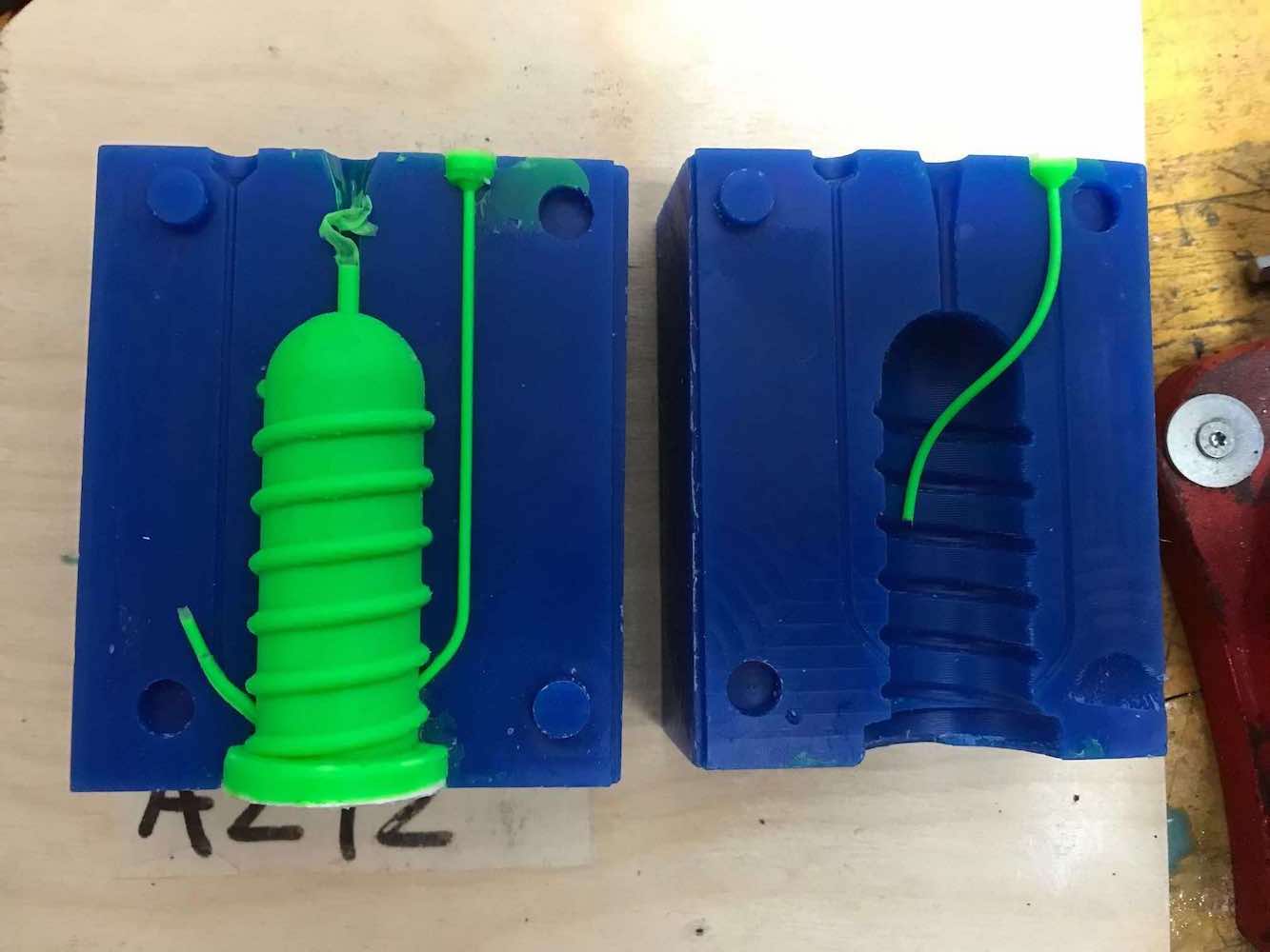
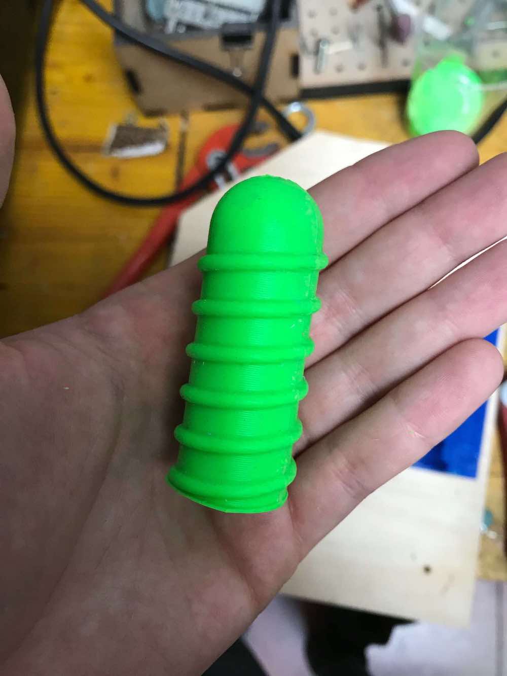
As I wrote earlier, the easiest way to customize Deeto’s measurements is by printing internal molds in different sizes. Here are three examples:
Bango
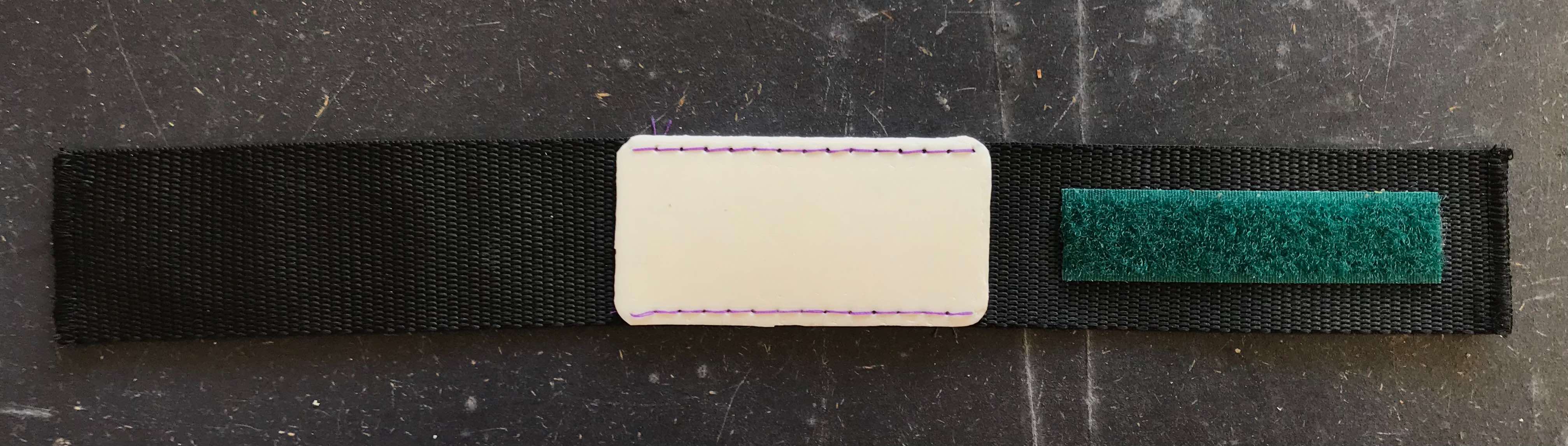
Bango is a hand-bracelet that can be widened or tightened using velcro depending on the size of the person’s hand. On the central part a small TPU pocket will be sewn by hand where you can fit cutlery or, why not, drawing tools or make-up tools.
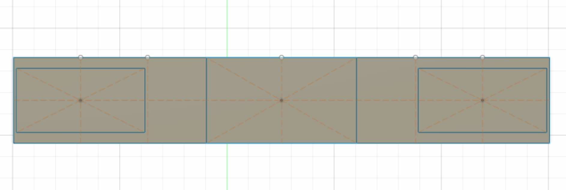
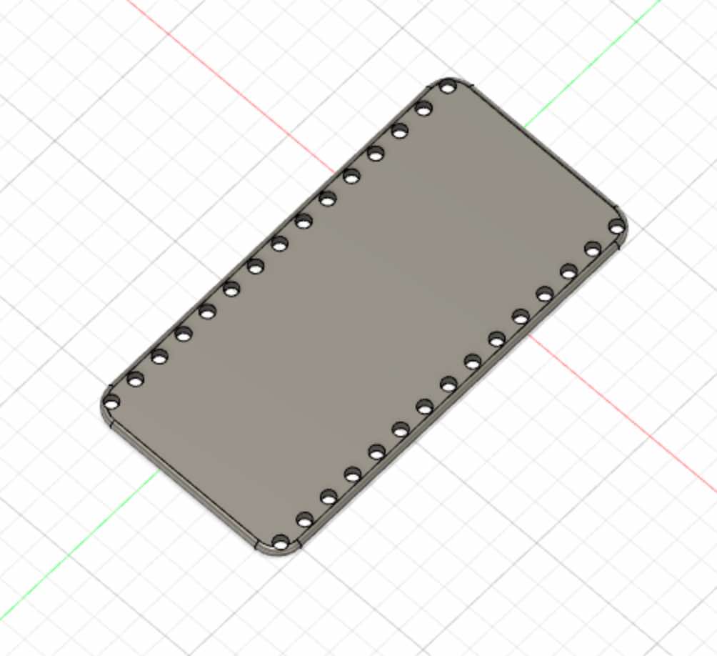
First we can make a cad for the bracelet and the pocket, which we will export later to print and cut them.
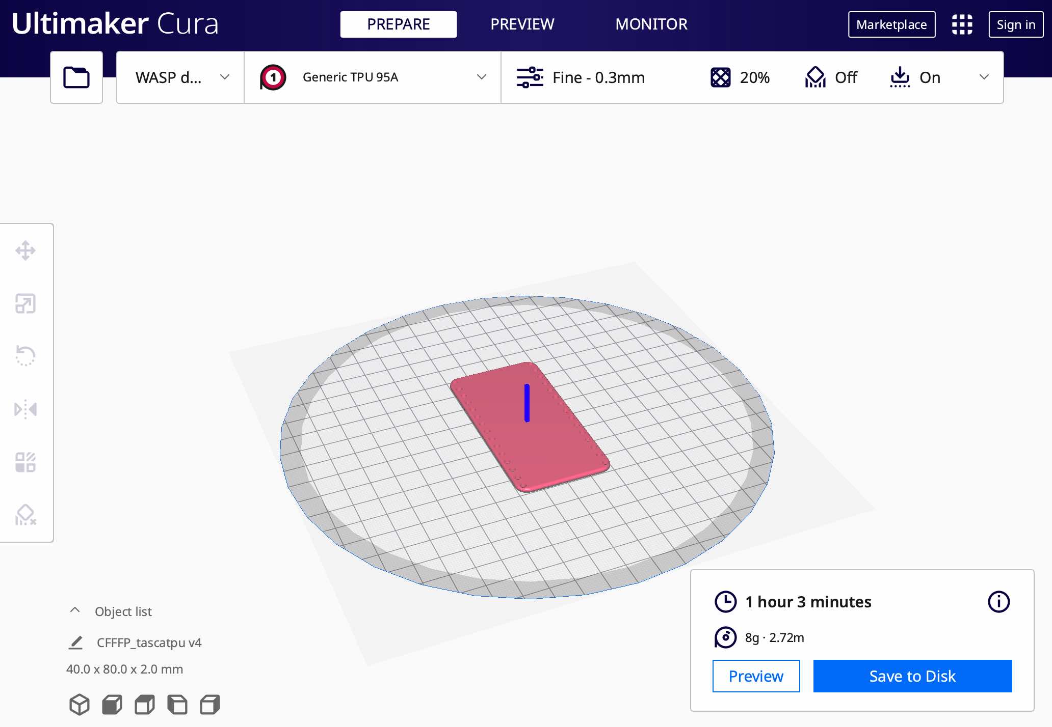
The pocket will be printed using TPU (Thermoplastic polyurethane), which is a polymer that is formed from the polycondensation of an isocyanate with a diol. The chemical nature of this chain influences the mechanical behavior and chemical resistance of the material: the longer the chain, the more the material assumes characteristics similar to natural rubber. TPU is one of the compounds with greater resistance to oils and abrasion, and is impermeable to water and gas. The excellent elasticity and the exceptional elongation ratio guarantee durability and resistance to tearing; in addition, TPU oxidizes less easily in the air than hydrocarbon-based rubbers.
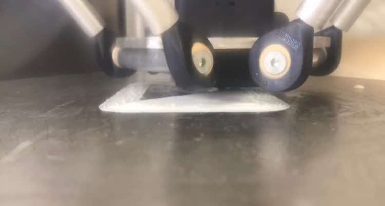
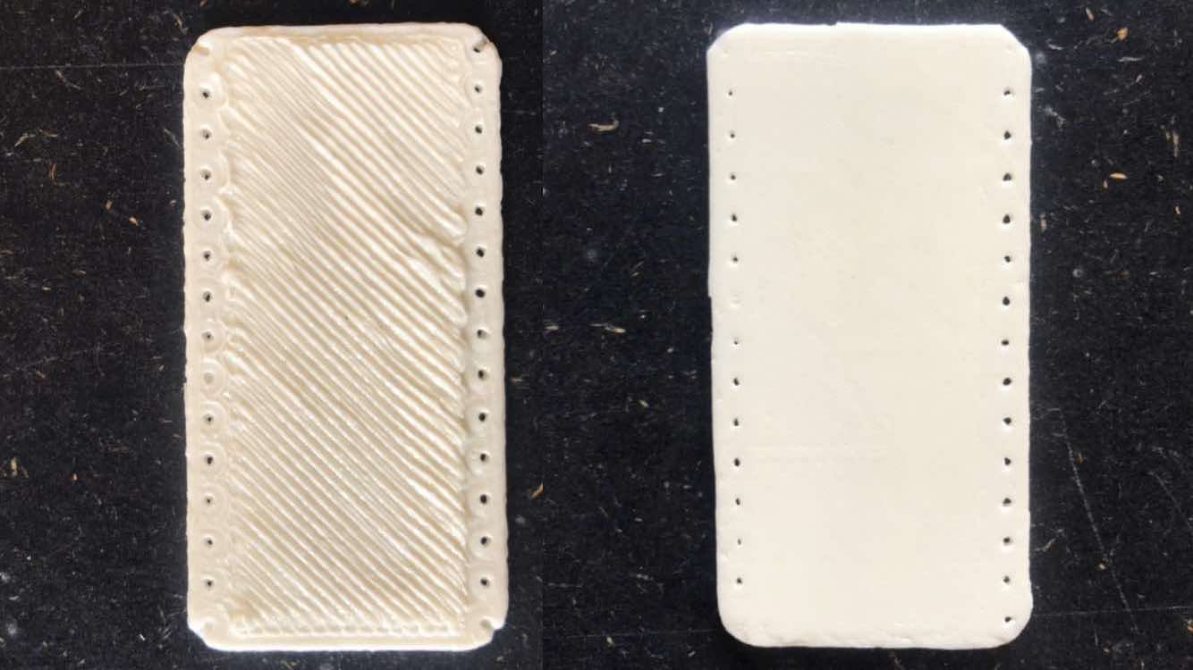
Before continuing I made two protypes to be sure that the chosen shape was the optimal one. I therefore used a piece of jeans in both prototypes, with the difference that in one I cut the TPU into strips and used buttons, while in the other I used the whole TPU and velcro.
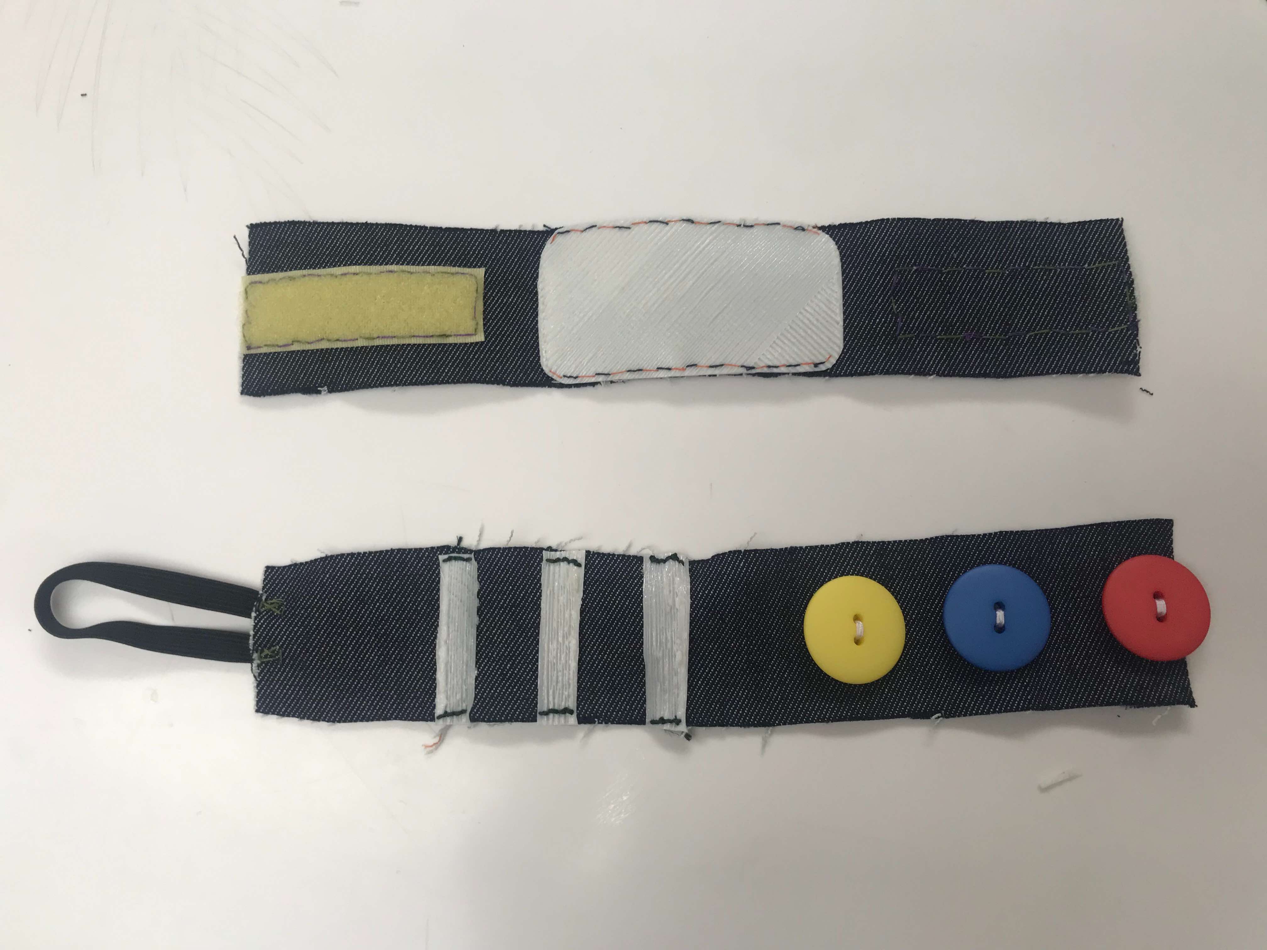
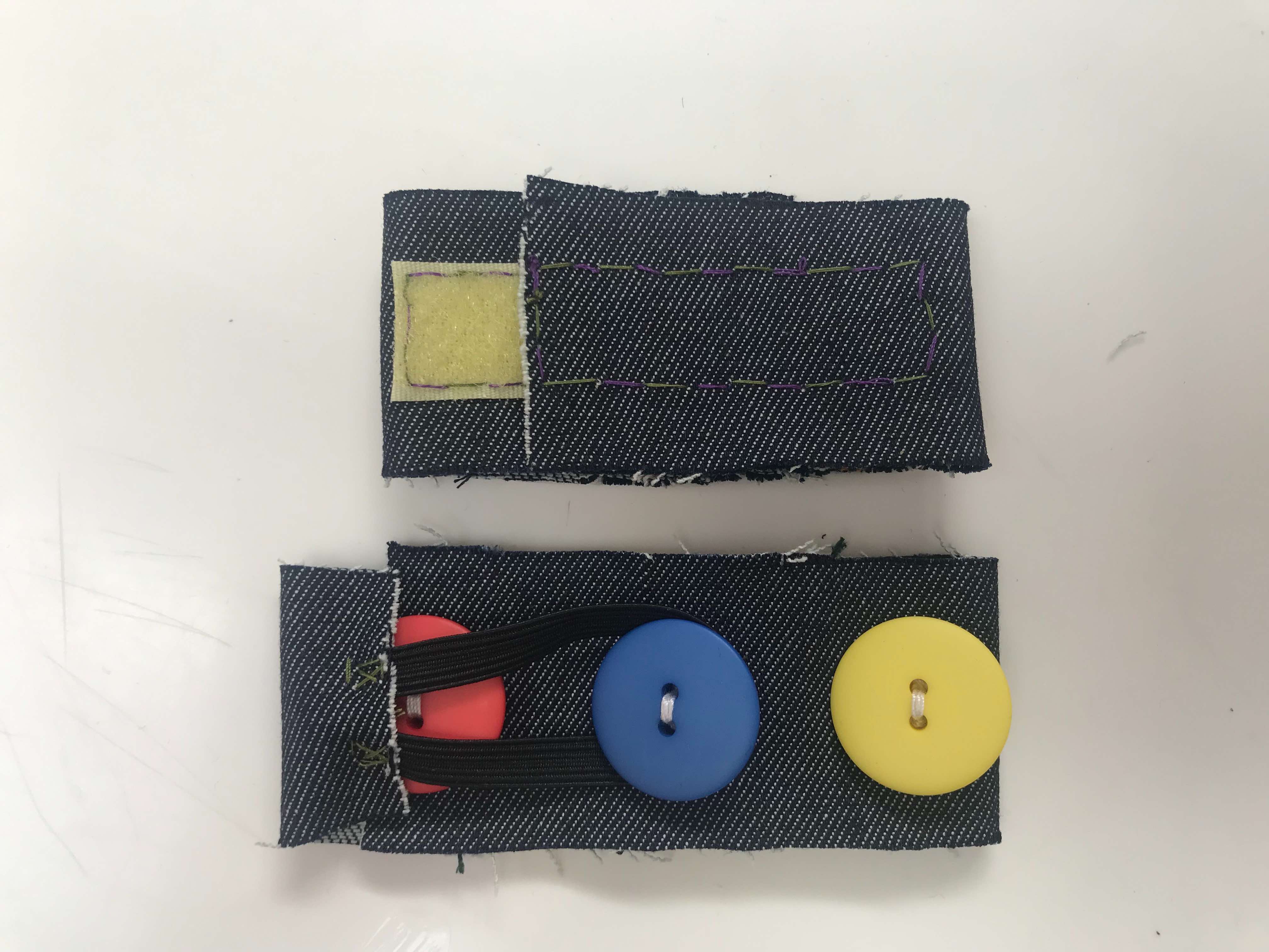
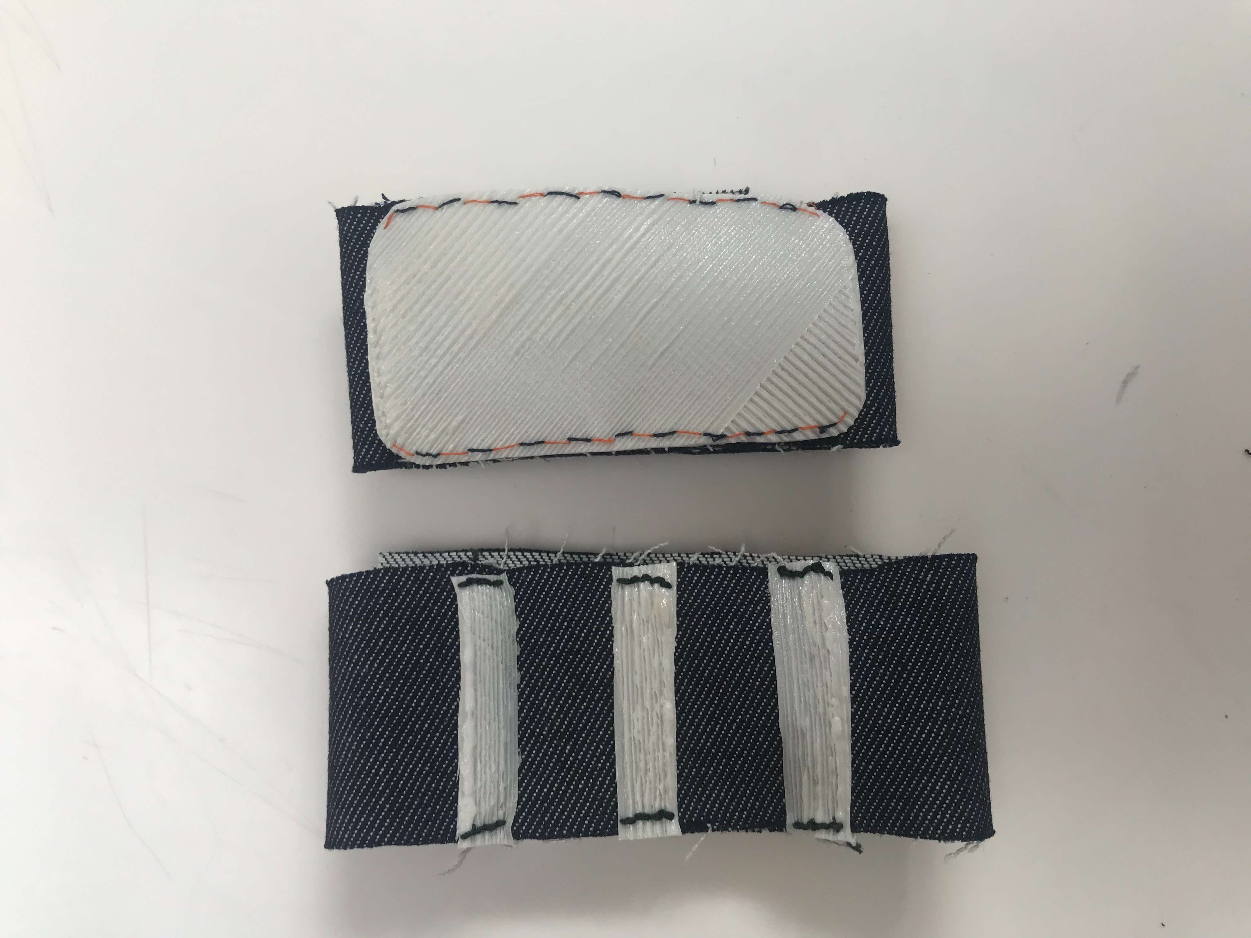
I realized that the velcro is easier to fasten and that the whole TPU is much more stable.
Now we can move on to the textile part, then cut the fabric for the base of the bracelet and the velcro. As fabric we will use polyester, which is super resistant and above all easy to clean.
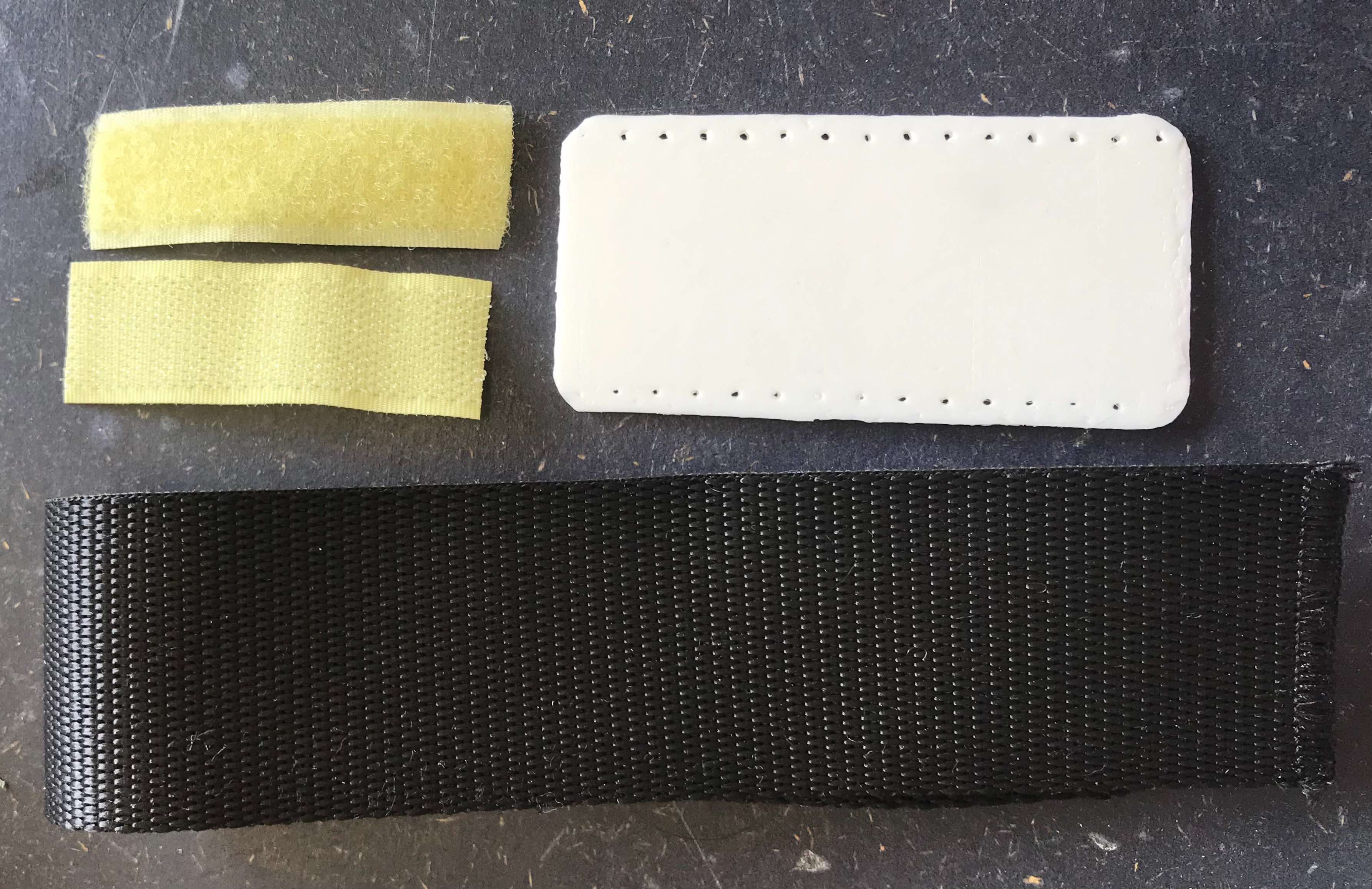
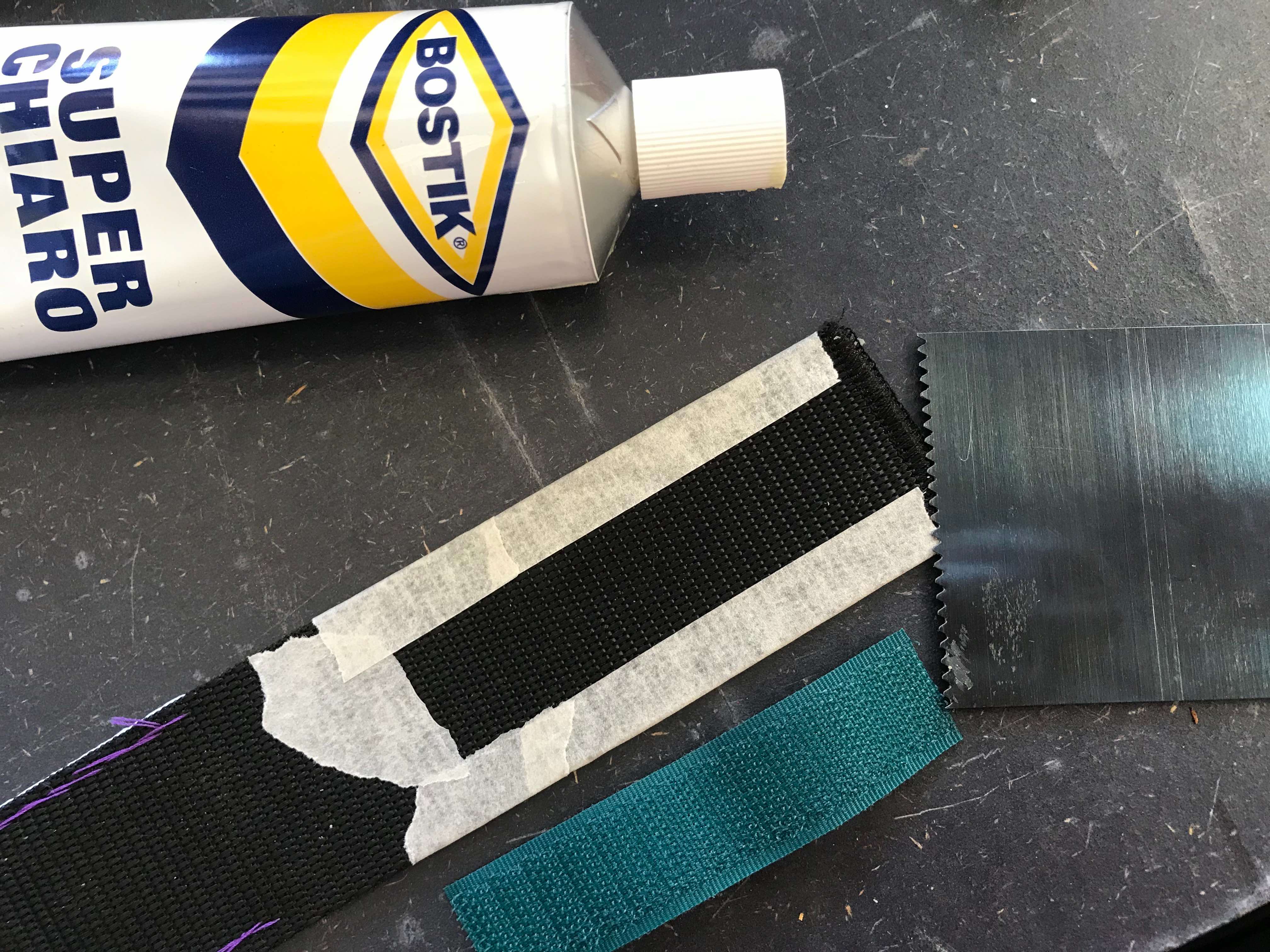
We therefore have all the components we need in hand, so let’s assemble them! First we sew the TPU pocket, then we glue the velcro to the ends of the bracelet.
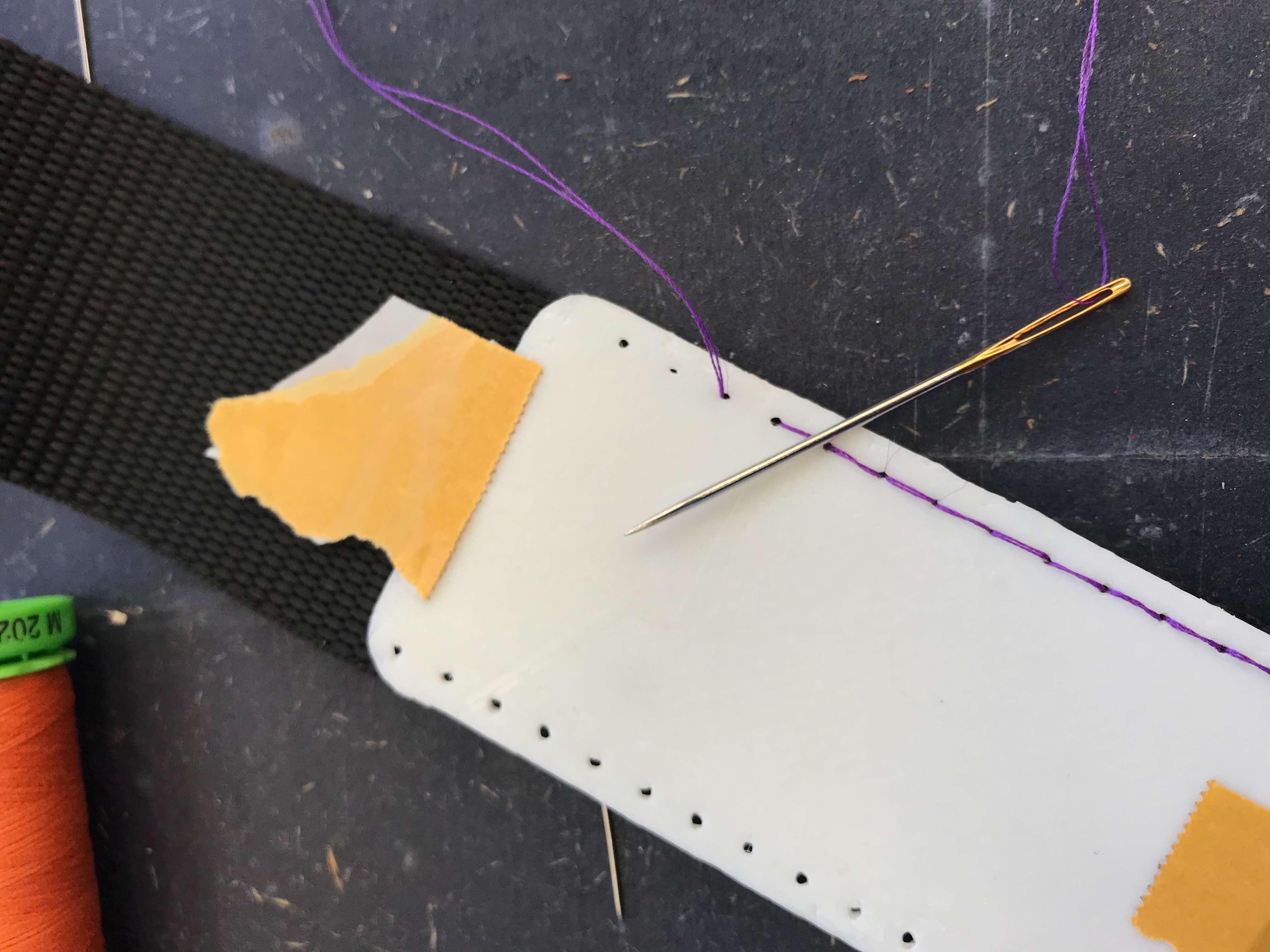
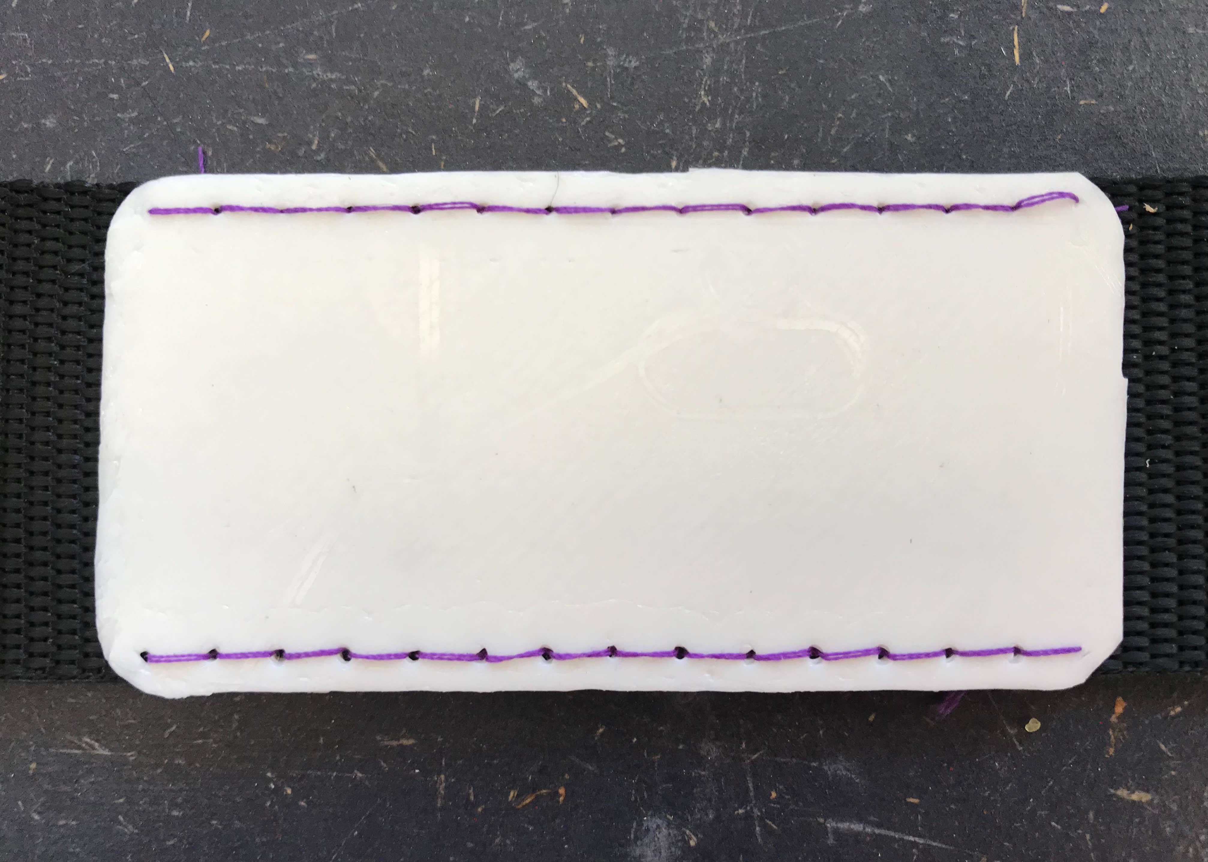
To glue I used mastic (bostik), which must be positioned both on the object to be glued and on the base, so to be more precise I made a frame with paper tape.
We just have to do a test with a spoon inserted in the pocket and…we are ready to go!
Willo
Willo is an emergency device, which through a capacitive proximity sensor perceives the touch or proximity of a body and sends a message via wifi to an app. I did not want to use a button as for some people with motor difficulties it can be complicated both to center the button and to apply the strength to activate it. In this case, a simple movement of any part of the body will be enough to send the alarm. This device will allow people to be more independent, because they can be left alone, knowing that in any moment of emergency they can ask for help from their doctor, health worker or caregiver via a notification from the app.
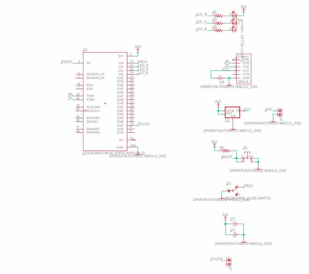
First of all we have to open Eagle and create the schematic of our PCB. The macro-components we are going to need are:
-
ESP32-WROOM-32 microcontroller: generic Wi-Fi + Bluetooth modules that target a wide variety of applications, ranging from low-power sensor networks to voice encoding, music streaming and MP3 decoding
-
RGB Led: to make sure the board is working once is connected to power
-
2 connectors: one for the external battery and one for the aluminium sheet
-
FTDI: to connect the pcb to our computer and program it
-
Switch slide: to switch from programming mode to operating mode
-
Voltage regulator: the microcontroller works with 3.3V, but external devices work at 5V, so we need this component to lower all powers to 3.3v
-
Button: to reset the board
-
Capacitors and resistors as usual
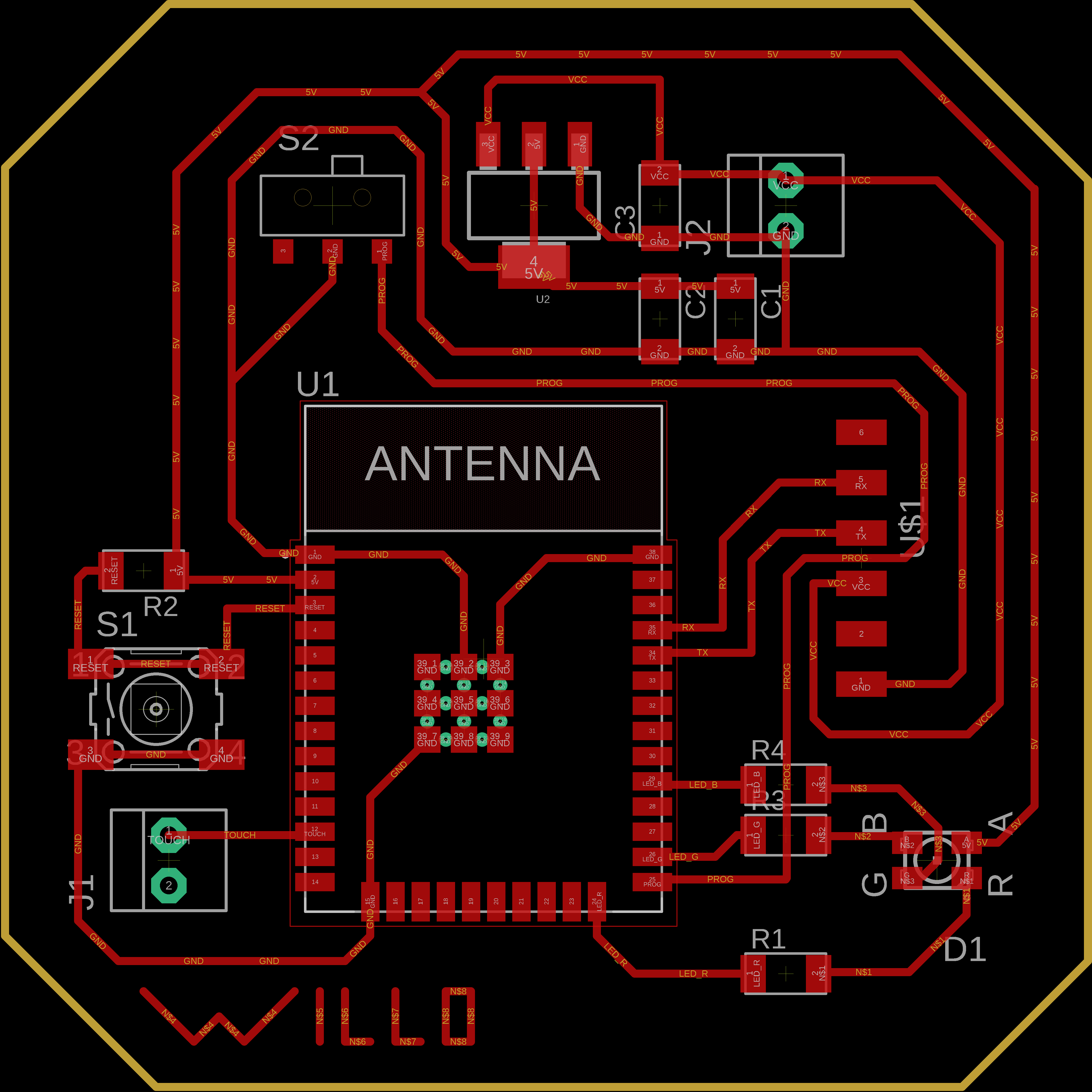
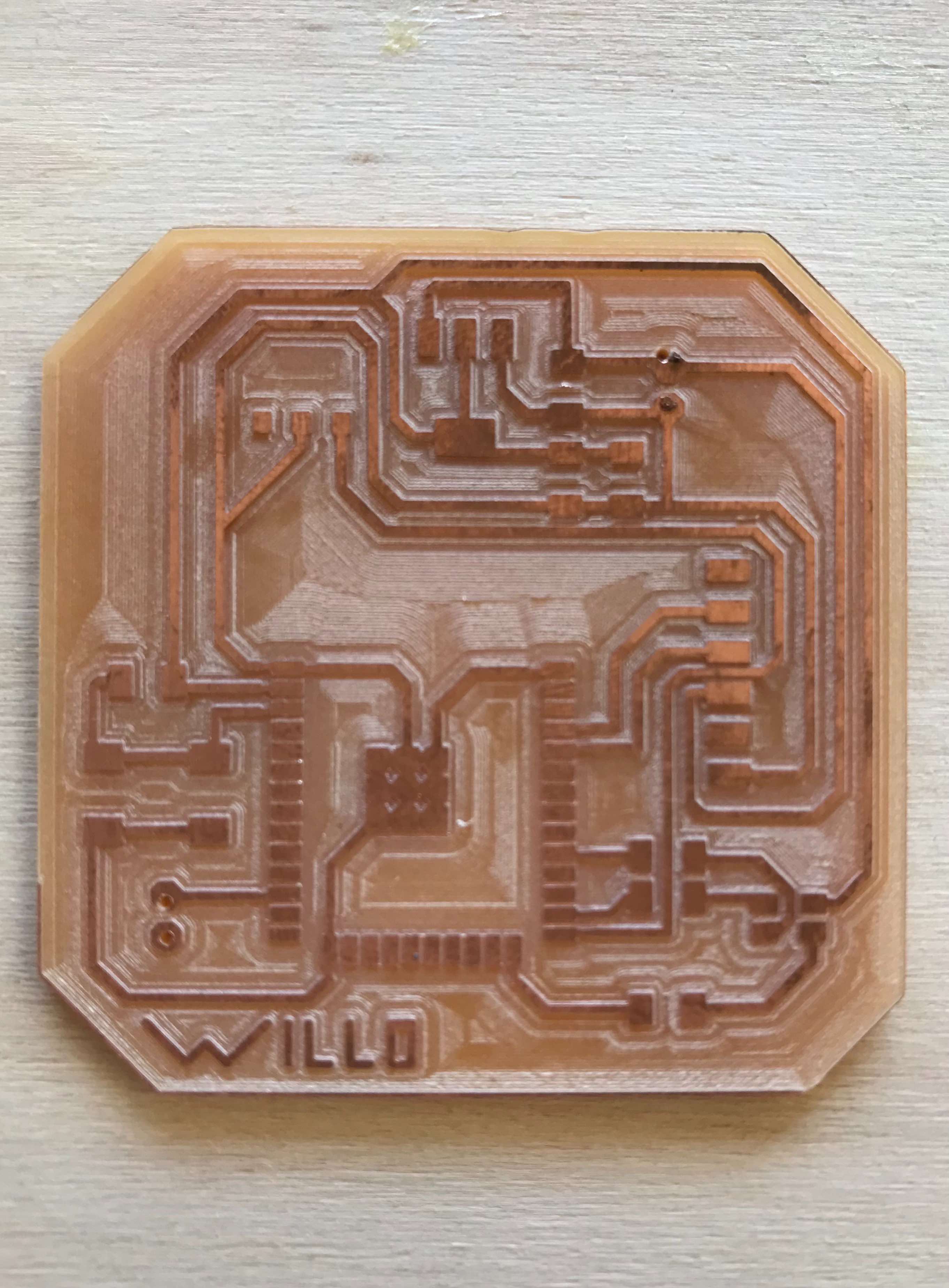
Once the schematic and the board are done, we can upload the files on fabmodules and create the code for the Roland MDX-40.
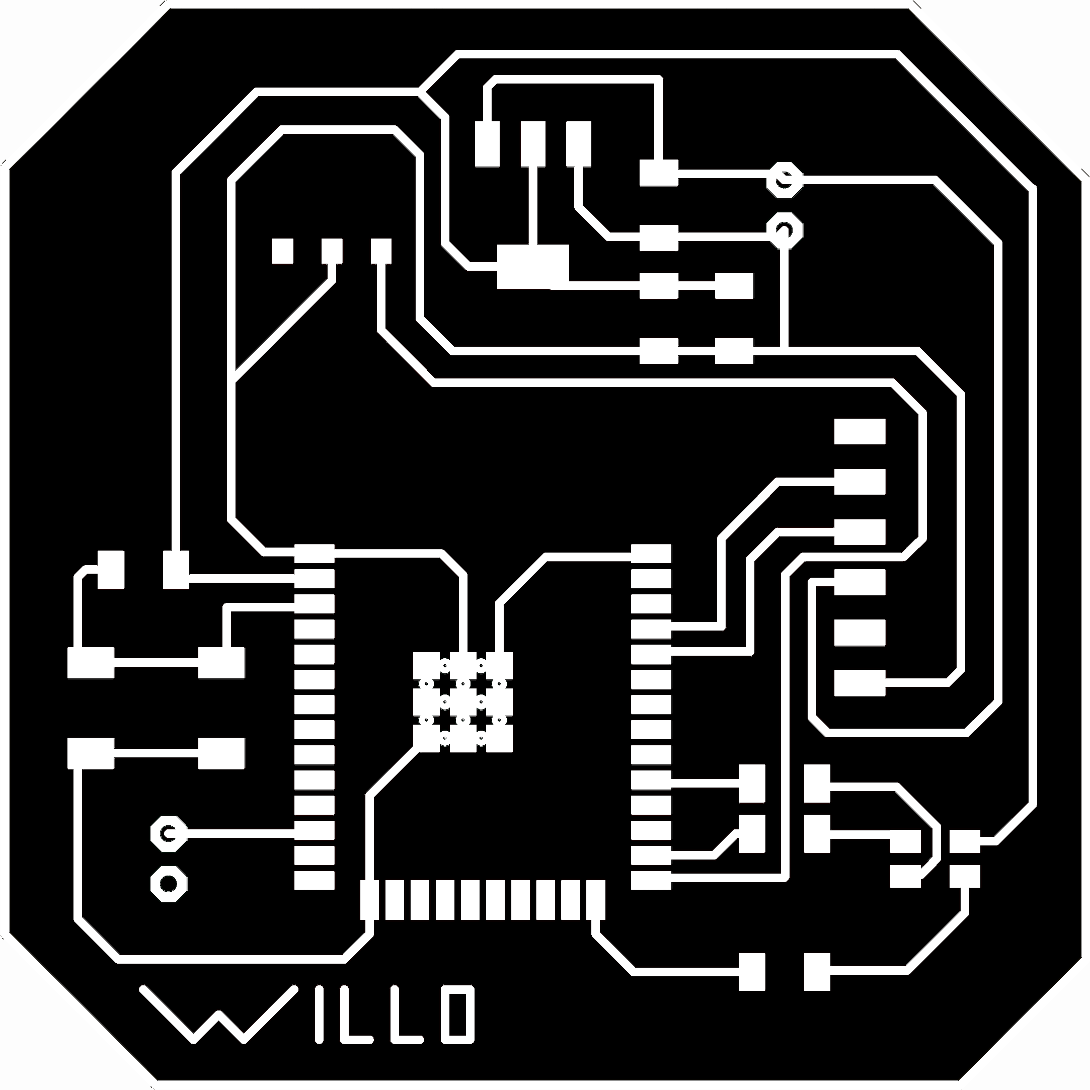
As usual we are going to use a 1/64 tip for the traces and a 1/32 tip for the outline. Since the traces of the microcontroller are very small, I created another code with a tool dimension of 0,3 mm, so that I’ll have a clean result.
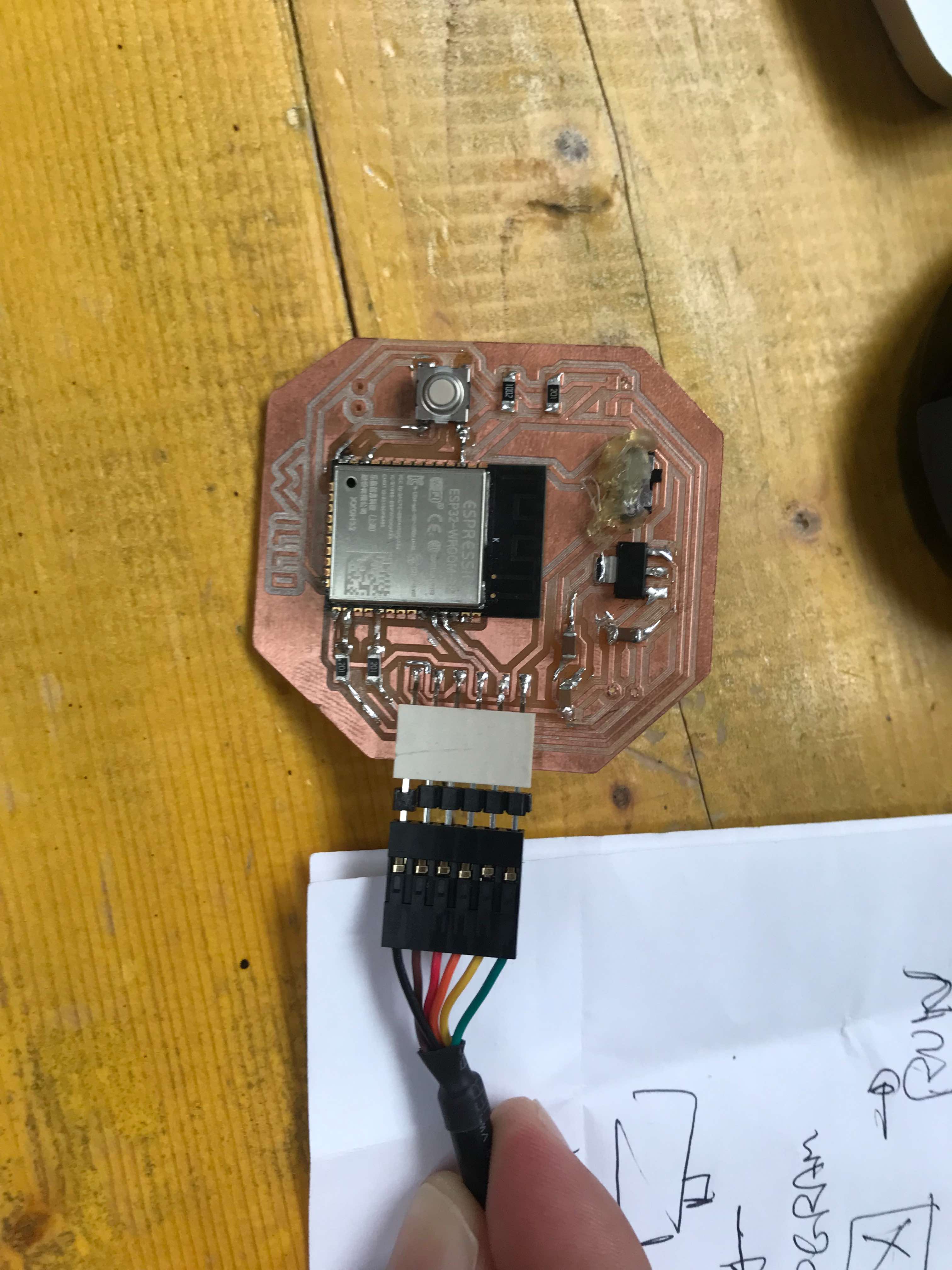
This is our fresh PCB milled and ready to be soldered!
Let’s program!
This is the code we are going to try. Once we have defined the variables, we can initialize the serial communication (void.setup). The wording led.routine is used to turn the led on and off cyclically. Touch sensor average is used to calibrate the pin, in fact the pin will be read more than 10 times to make an average (baseline). In void.loop I declare the touch variable and use it both to compare it with the baseline value and to send a message to the serial monitor.
// #define WIFI

#ifdef WIFI
#include "WiFi.h"
#endif

// Capacitive touch sensor pin
#define TOUCH_PIN 12

// RGB LED pins
#define LED_R 24
#define LED_G 26
#define LED_B 29

// wifi setup
String wifiSSID = "";
String wifiPass = "";

int touchBaseline;

void setup() {
  Serial.begin(115200);
  Serial.println("Sketch start");

  // LED setup
  pinMode(LED_R, OUTPUT);
  pinMode(LED_G, OUTPUT);
  pinMode(LED_B, OUTPUT);
  ledRoutine();

  // Touch sensor average baseline setup
  int accumulator = 0;
  int n = 10;
  for (short i = 0; i < n; i++) {
    accumulator += touchRead(TOUCH_PIN);
  }
  touchBaseline = accumulator / n;
  Serial.print("baseline: ");
  Serial.println(touchBaseline);

  #ifdef WIFI
  // Connect to wi-fi
  WiFi.mode(WIFI_STA);
  Serial.print('\n');
  Serial.println("Connecting to WiFi...");
  WiFi.begin(&wifiSSID[0], &wifiPass[0]);
  while (WiFi.status() != WL_CONNECTED) {
    delay(1000);
    Serial.println("... nothing yet ...");
  }
  Serial.println("Connected");
  Serial.print("IP address: ");
  Serial.println(WiFi.localIP());
  #endif
}

void loop() {

 int touch = touchRead(TOUCH_PIN);
 if (touch < touchBaseline) {
    Serial.println("Touch sensor activated");
    Serial.println(touch);
    delay(200);
    //ledRoutine();
  }
}

void ledRoutine() {
  for (short i = 0; i < 3; i++) {
    digitalWrite(LED_R, LOW);
    digitalWrite(LED_G, LOW);
    digitalWrite(LED_B, LOW);
    delay(50);
    digitalWrite(LED_R, HIGH);
    delay(50);
    digitalWrite(LED_G, HIGH);
    delay(50);
    digitalWrite(LED_B, HIGH);
    delay(100);
  }
  digitalWrite(LED_R, LOW);
  digitalWrite(LED_G, LOW);
  digitalWrite(LED_B, LOW);
}
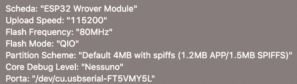
Once we have selected all the different settings:
We are ready to upload our code:
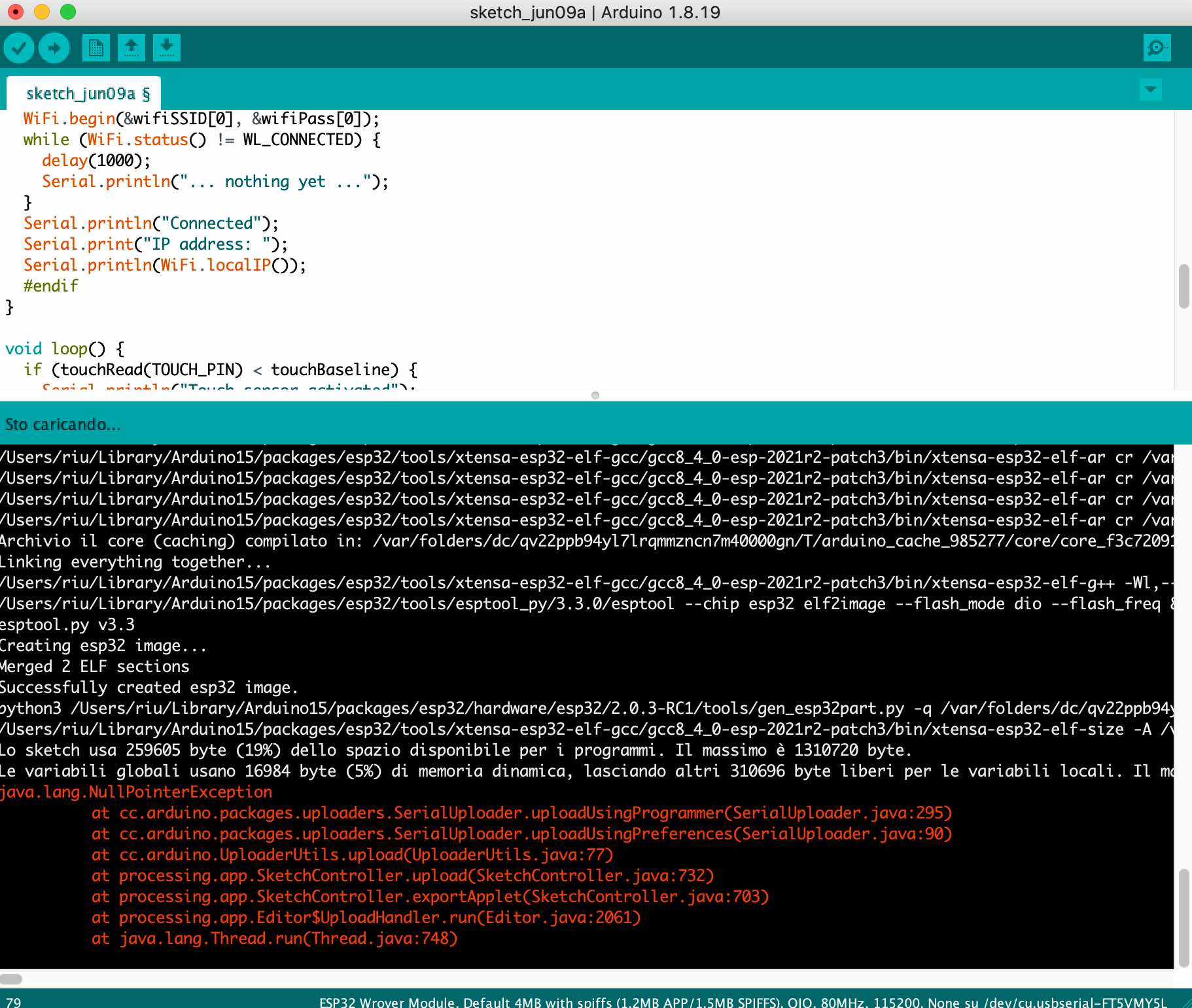
And hope this is the final response:
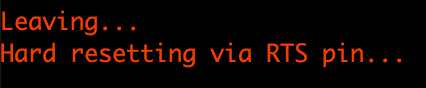
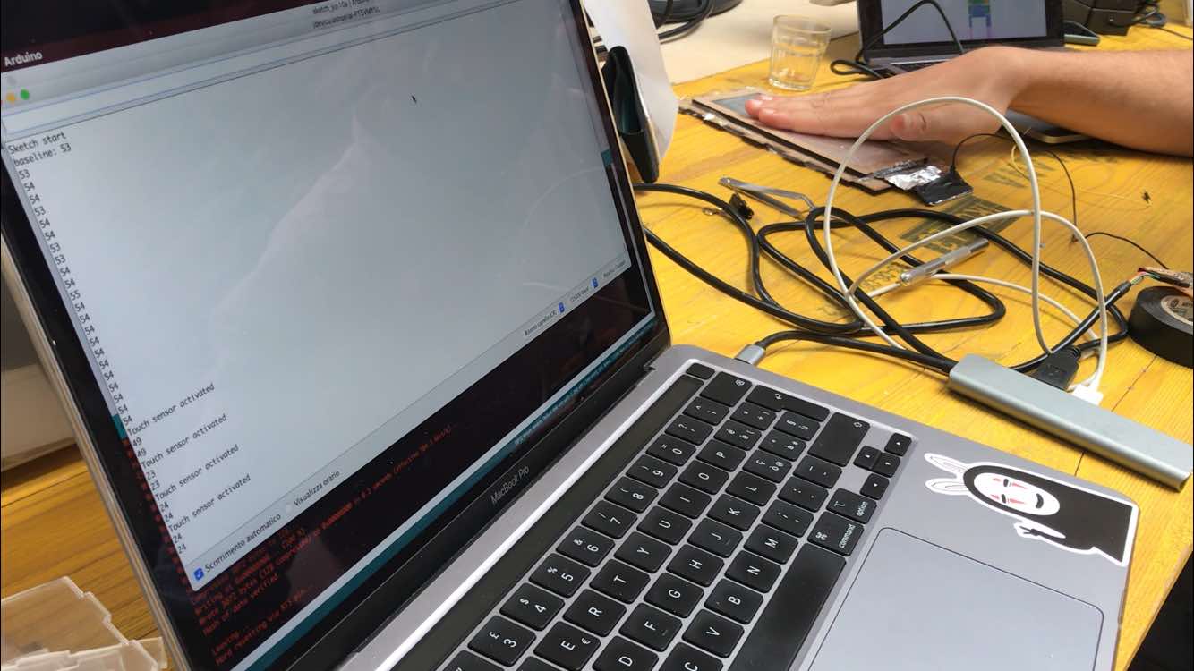
Now we can go to our serial monitor, turn off the switch, click reset and the calibration will start.
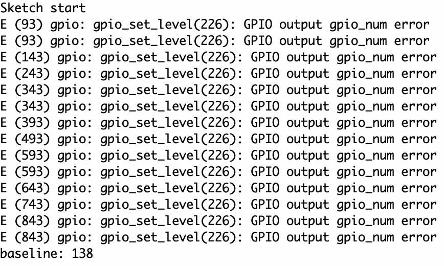
Now if everything works correctly, the moment we touch our foil plane, the sensor will begin to perceive the proximity of our hand, and different values will be written in the serial monitor depending on the proximity!
Next thing is we are going to connect to our board a battery and a simple aluminium sheet (foil will be just fine). The battery is going to be a LiPo (Lithium Polymer) of 3.3V.
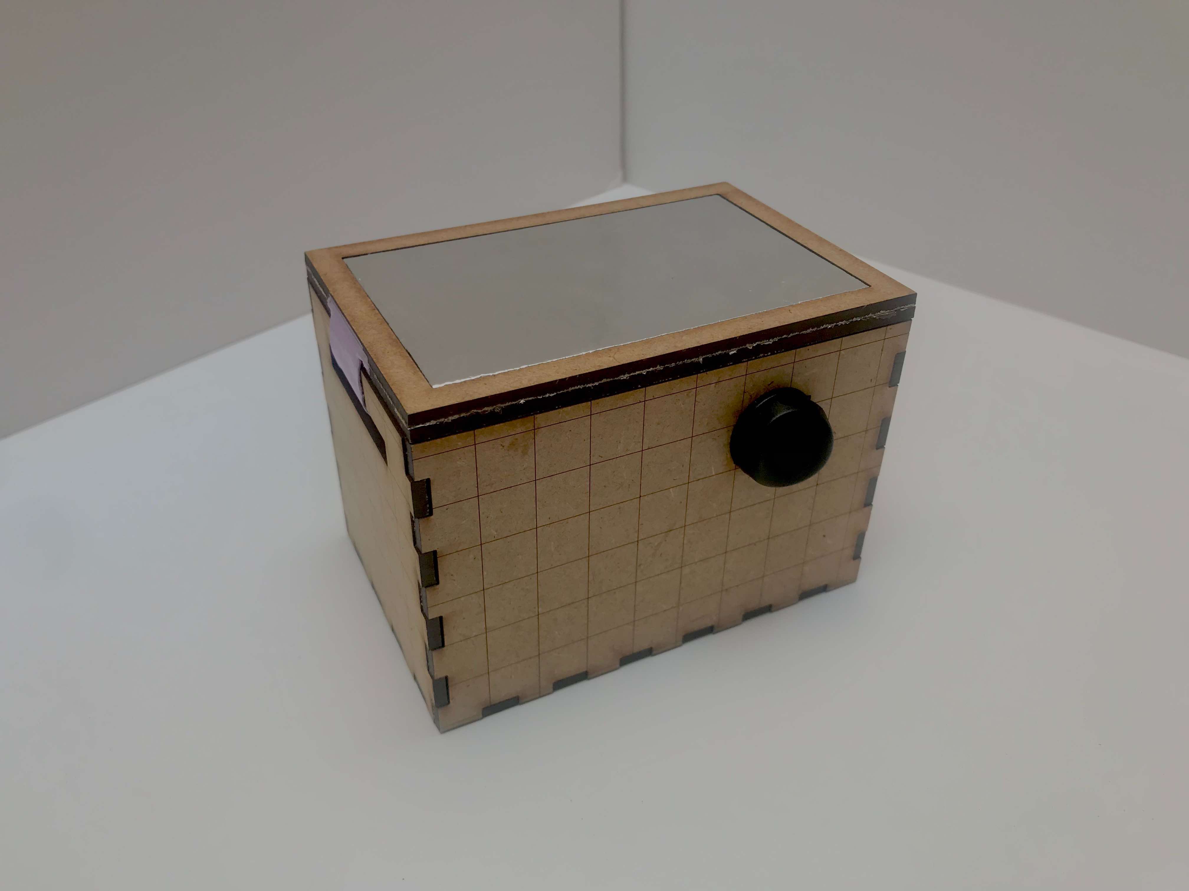
Once everything is soldered we put everything in a little lasered box, and the only thing we’re going to see is the aluminium on the top, covered by a thin layer of plastic to protect it.
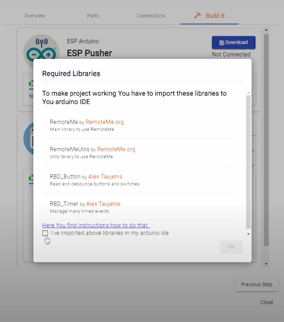
Here comes the part where we have to make communicate our ESP32 with a cellphone. To make that I used RemoteMe, a free, customizable system which helps you to communicate with your IoT devices. They provide coding wizards to automatically generate webPages and sketch so you don’t have to code everything from scratch. This is the video-tutorial to Send Push notification to android app from ESP.
The site is very easy to use, once logged in we go to the projects section “out of the box” and select the type of app we want to make.
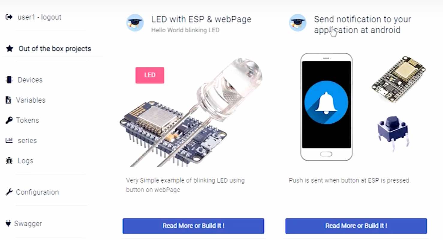
When the button connected to ESP is pressed, a notification will be sent to your android app. You don’t have to install anything on your smartphone, there’s a QR code to scan. You will be asked what type of ESP you are using and the wifi name and password. At this point, a code will be created (remember to download the libraries it suggests) that we can modify at a later time, and a website to control everything via smartphone.
This is the edited code:
#include "WiFi.h"
// RemoteMe
#define DEVICE_ID 1
#define DEVICE_NAME "ESP Pusher"
#define TOKEN "~1258186_Gj88Je4s2nQLDpywHWogz1Wq"
#include <RemoteMe.h>
#include <RemoteMeSocketConnector.h>
// Capacitive touch sensor pin
#define TOUCH_PIN 27
// RGB LED pins
#define LED_R 4
#define LED_G 5
#define LED_B 2
// wifi setup
String wifiSSID = "opendot";
String wifiPass = "opendotlab";
int touchBaseline;
bool touchActive;
RemoteMe& remoteMe = RemoteMe::getInstance(TOKEN, DEVICE_ID);
void setup() {
Serial.begin(115200);
Serial.println("Sketch start");
// LED setup
pinMode(LED_R, OUTPUT);
pinMode(LED_G, OUTPUT);
pinMode(LED_B, OUTPUT);
turnLED(HIGH, LOW, LOW);
// Touch sensor average baseline setup
int accumulator = 0;
int n = 10;
for (short i = 0; i < n; i++) {
accumulator += touchRead(TOUCH_PIN);
}
touchBaseline = accumulator / n;
Serial.print("baseline: ");
Serial.println(touchBaseline);
// Connect to wi-fi
WiFi.mode(WIFI_STA);
Serial.print('\n');
Serial.println("Connecting to WiFi...");
WiFi.begin(&wifiSSID[0], &wifiPass[0]);
while (WiFi.status() != WL_CONNECTED) {
delay(1000);
Serial.println("... nothing yet ...");
}
Serial.println("Connected");
Serial.print("IP address: ");
Serial.println(WiFi.localIP());
turnLED(LOW, LOW, HIGH);
touchActive = false;
remoteMe.setConnector(new RemoteMeSocketConnector());
remoteMe.sendRegisterDeviceMessage(DEVICE_NAME);
}
void loop() {
if (!remoteMe.loop()) { //no connection established
return;
}
if (touchRead(TOUCH_PIN) < touchBaseline) {
if (!touchActive) {
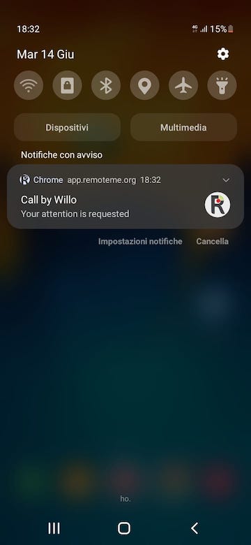
String body = "Your attention is requested";
remoteMe.sendPushNotificationMessage(2, "Call by Willo", body, "badge.png", "icon192.png", "");
Serial.println("Touch sensor activated");
turnLED(HIGH, LOW, HIGH);
touchActive = true;
}
} else {
if (touchActive) {
turnLED(LOW, LOW, HIGH);
touchActive = false;
}
}
delay(200);
}
void turnLED(bool r, bool g, bool b) {
// contrary because of common anode
digitalWrite(LED_R, !r);
digitalWrite(LED_G, !g);
digitalWrite(LED_B, !b);
}
In the initial part define we make communicate our microcontroller with RemoteMe. token is a unique value of our board. In the void.setup part we have the initialization of the LED, where we also choose the initial color (RED). Then the sensor calibration to give a baseline value, as we saw in the previous code. Finally, the connection to WiFi with also a color change of the LED (BLUE). In the void.loop part three main things happen when we touch the surface:
- communication with RemoteMe takes place via a message (Notification)
- LED color change
- enables touchActive (when we touch the surface for a certain time, only one notification will be sent until the hand is removed from it).
In the end there are some tricks regarding the RGB LED. As we all know, this type of LED has 4 pins but only 1 anode, this means that it works in reverse compared to a normal LED. That is, pins R G and B are connected directly to the microcontroller, while the other pin is connected to VCC. This means that there is a continuous flow of power, and if I want a led to turn on it will be technically off and will act as GND. For example, if I want to see the red light, I will have the pins of G and B on, while that of R off, so that it doesn’t block the VCC and let the power “pass”.
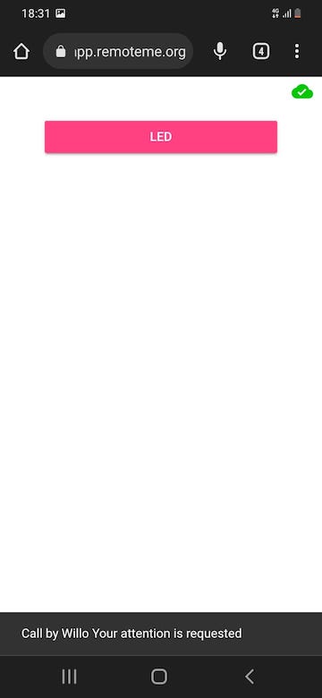
Now if we touch the sensor, the “app” will send a notification to the smartphone!
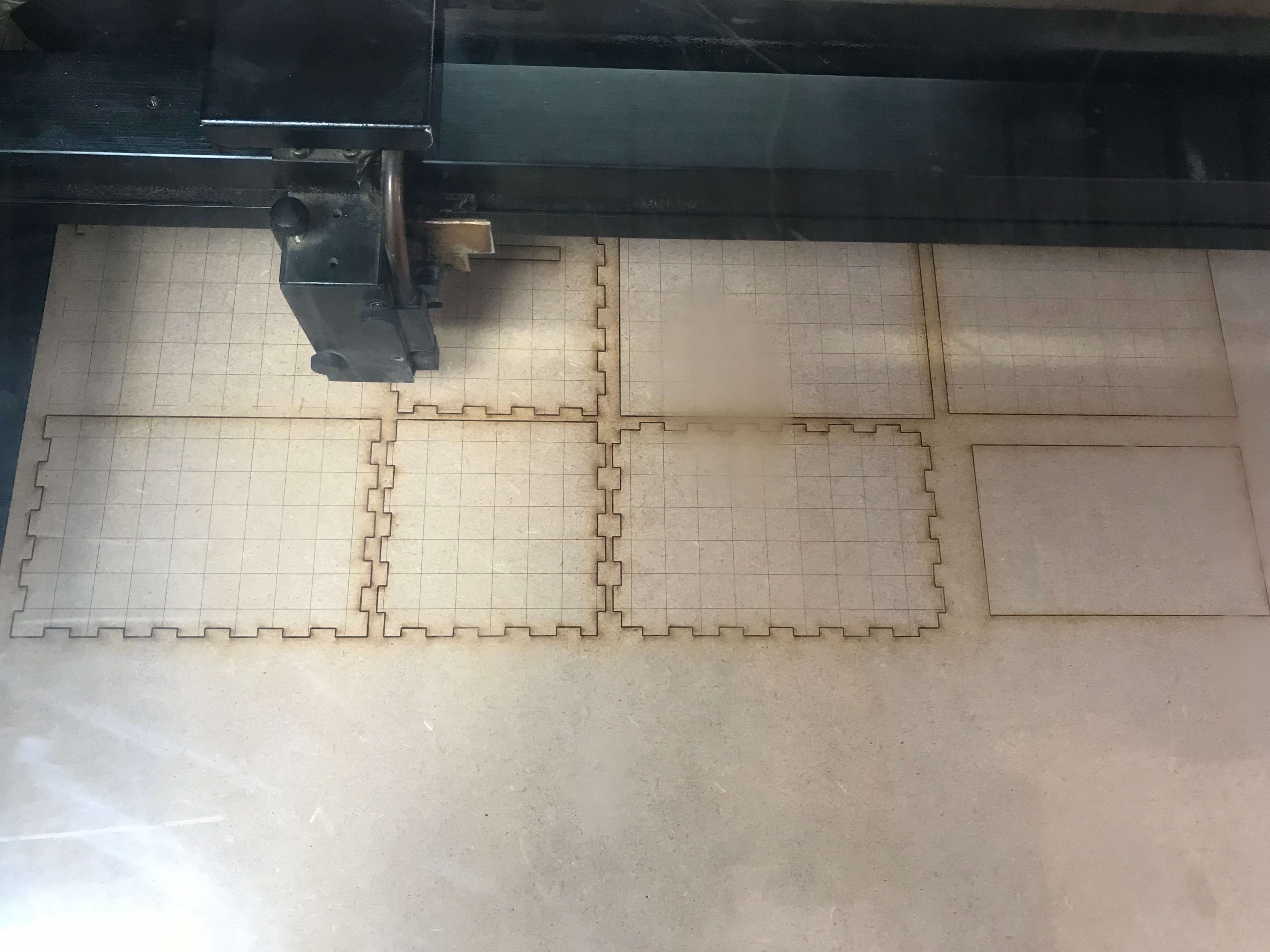
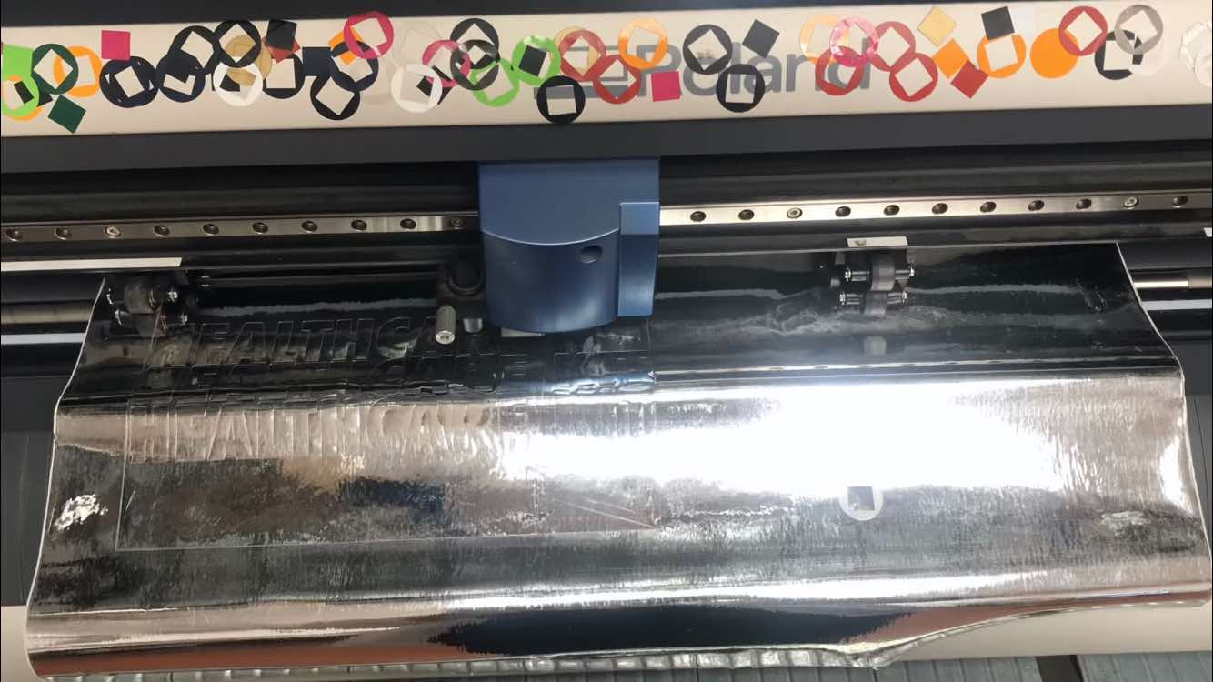
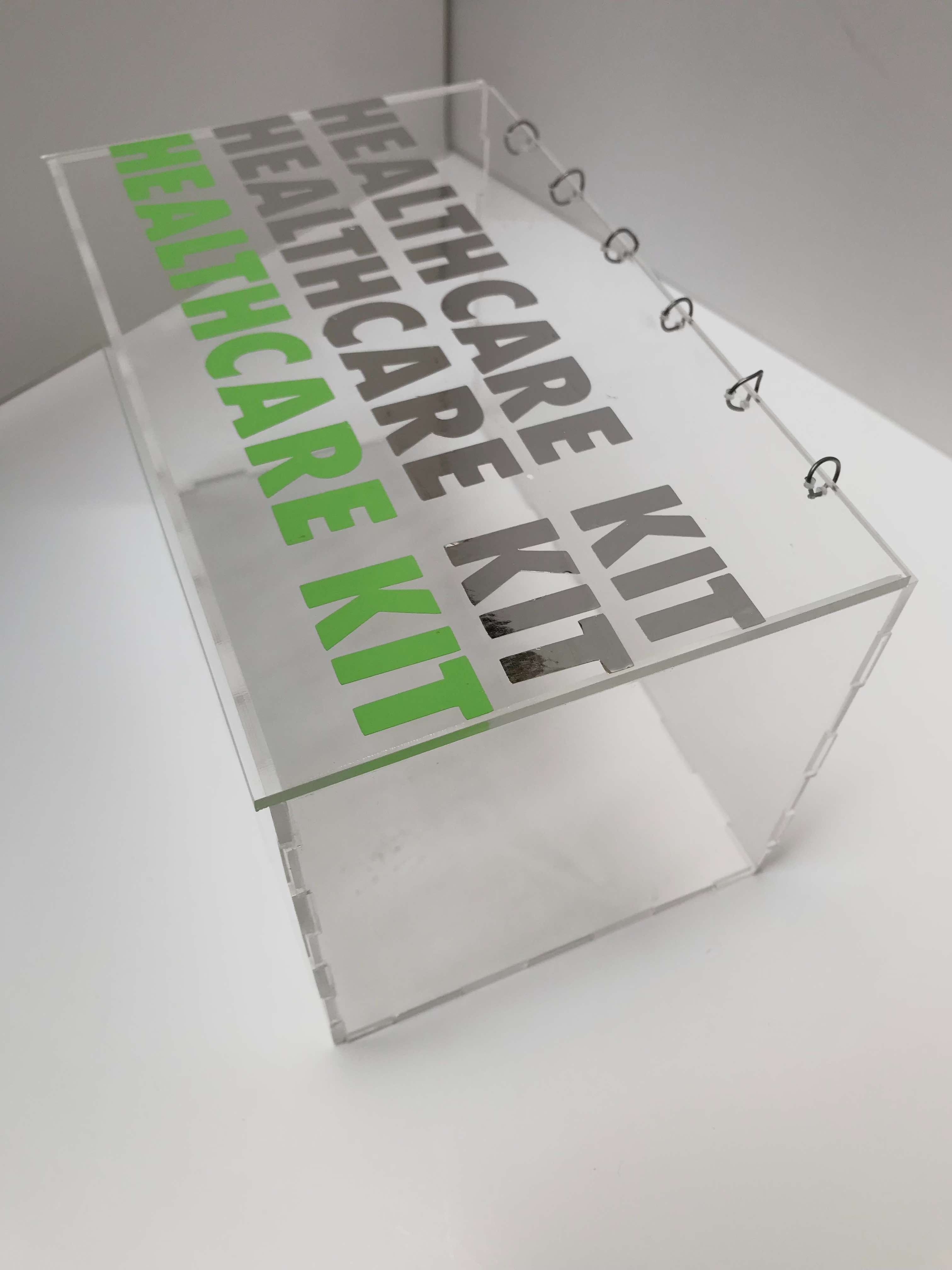
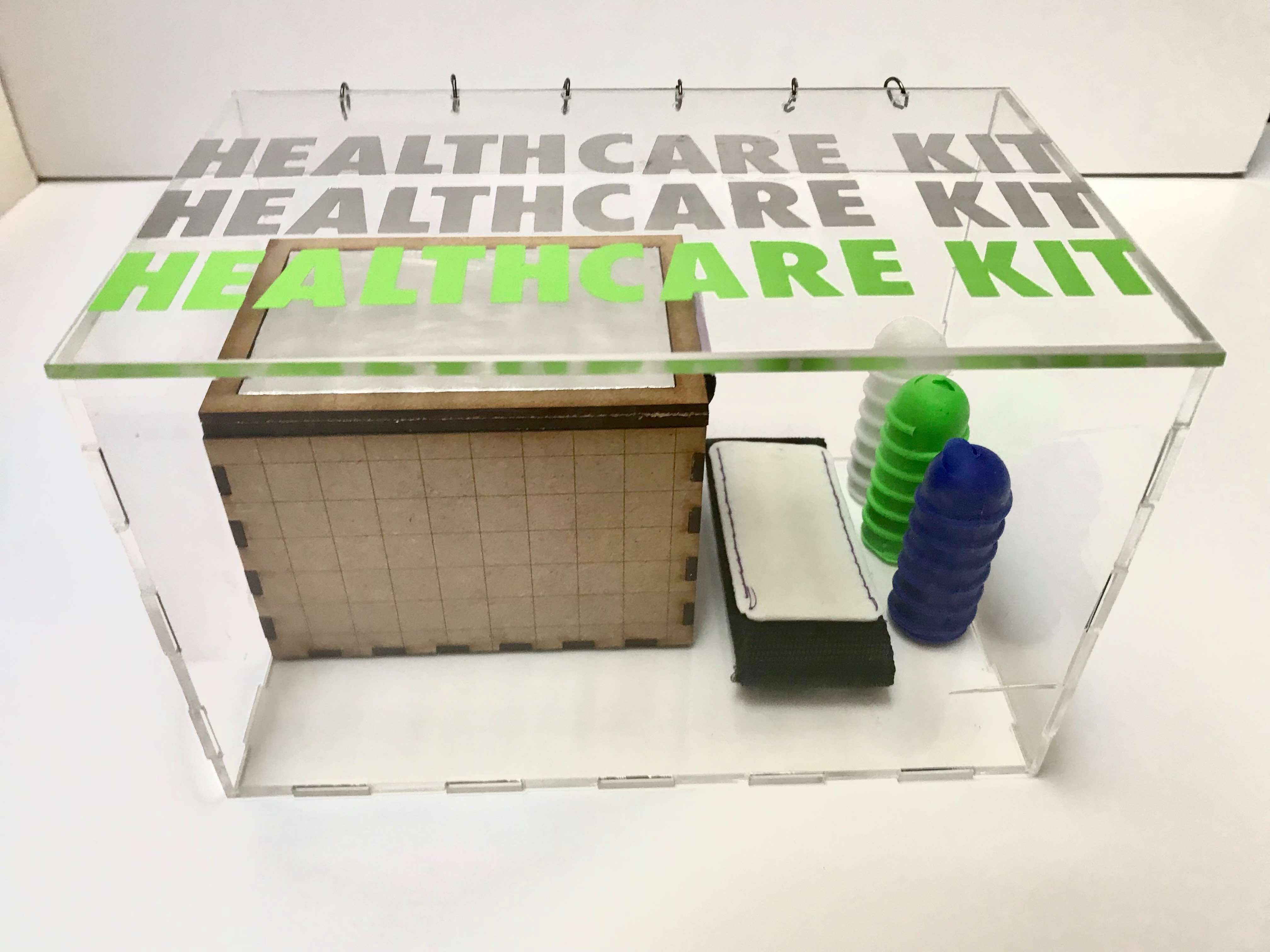
Packaging
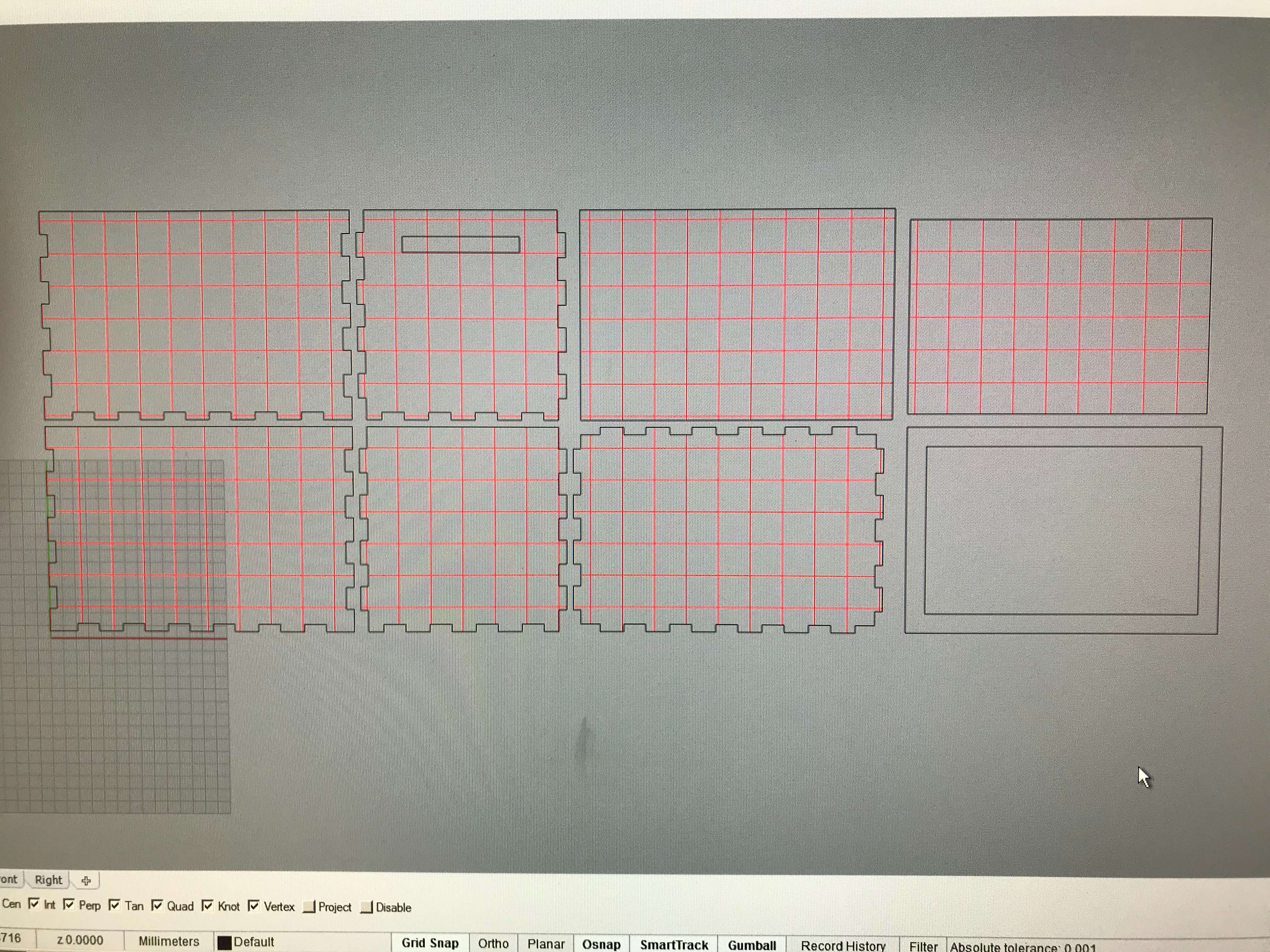
Now that we have our three objects done, we can think about the box to put them in. We are going to use a lasercutter, since the material of the box is acrylic, and a vinyl cutter, to decorate it. In doing so we will use all the machines of the lab!
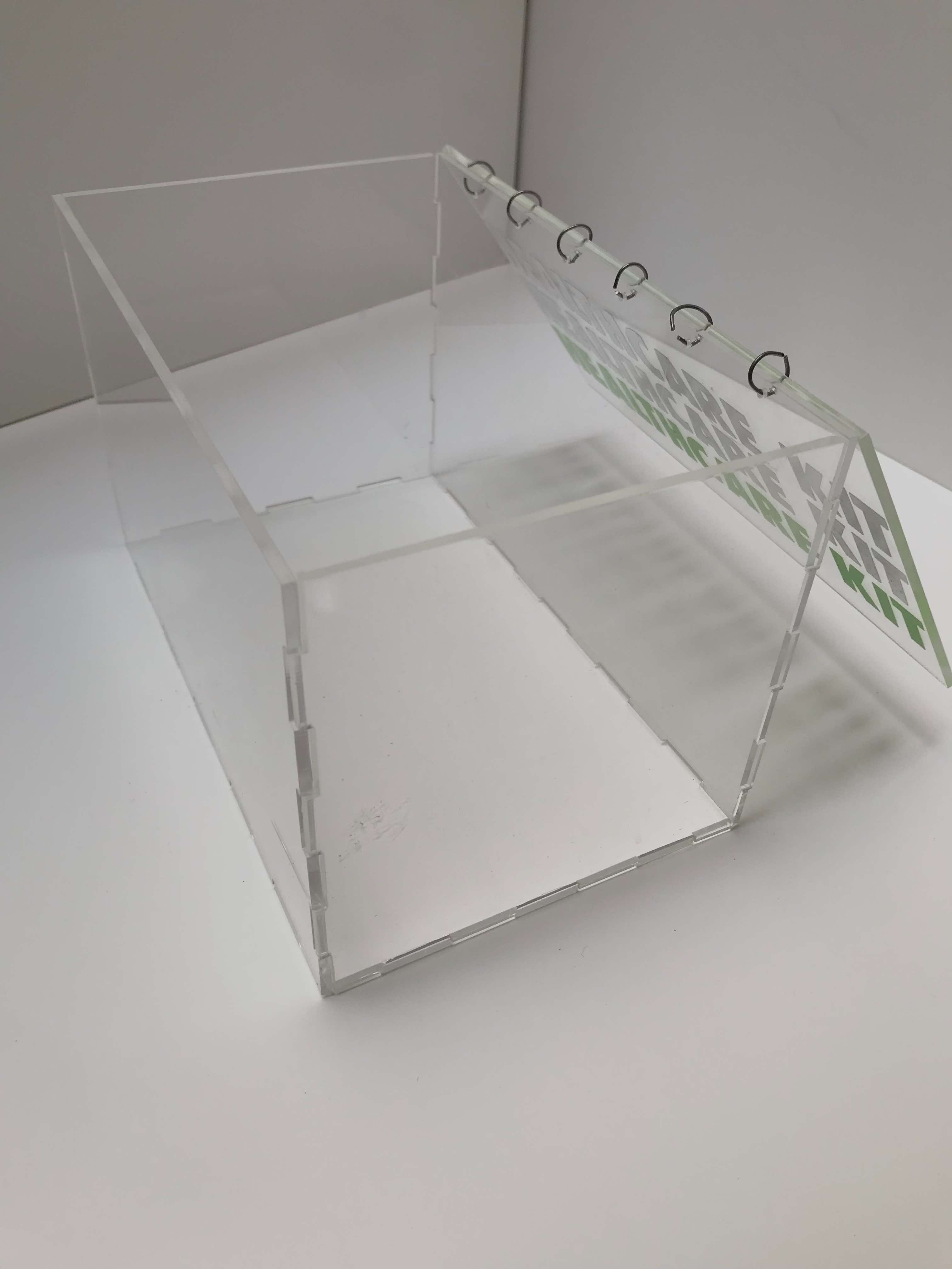
Obviously we will have to think of a box that is easy to open, otherwise we will go against everything we have done so far. In addition to the acrylic we will use wire to open and close the box, while the rest of the faces will remain united through joints. We will also add an elastic on the upper face to facilitate the opening of it.
Here’s the CAD of the box, and the file to use for the vinylcutter:

And the box and the sticker in the making!
Result
Materials
As for the materials and their cost, I mainly used waste materials already present in the lab, such as MDF, fabric, adhesive sheets, wax and so on. Let’s see specifically the cost of the other materials. A transparent acrylic sheet costs around 14€, but considering that I used less than half of it, the total cost amounts to a maximum of 6€. The silicone that I used Silplay 184 has a cost of about 30€ for a total of 500 g, so if I wanted I could have made 30 Deetos. The Ninjaflex TPU costs around 50€, but for my Bango pocket I have spent less than 5€ total. As for the electronics part, I used all components already present in the lab (except RGB LEDs), all purchased on Digi-Key, and I have reached a maximum figure of 20€.
Useful links
Files
Project 1:
Project 2:
Project 3:
Packaging: