7. Electronics design
For this week’s assignment we had to redraw an echo hello-world board, add (at least) a button and LED (with current-limiting resistor), check the design rules, make it, and test that it can communicate. After choosing to mill a t45-echo board that I found in Neil’s documentation, I downloaded Eagle.
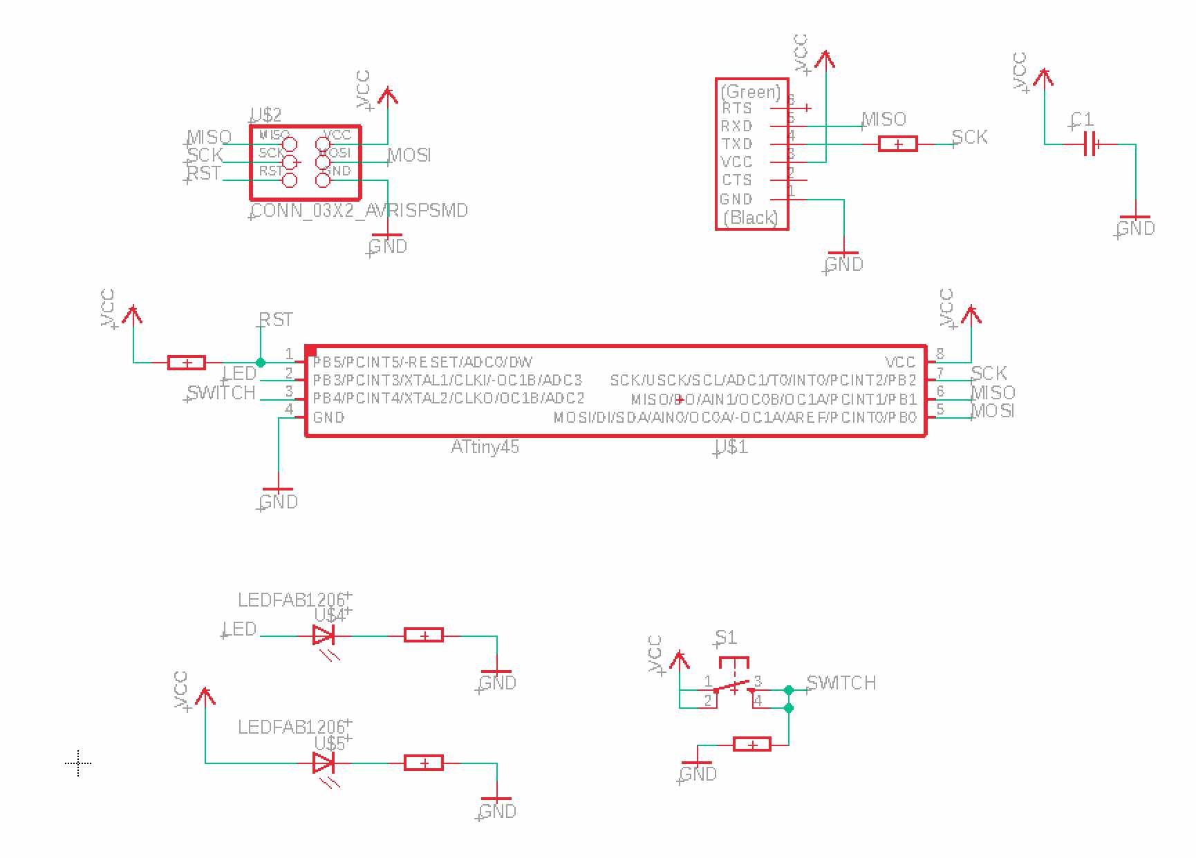
To start drawing you need to open a Schematic file, in which we can add the components we need and create links between them, subsequently defining the rules and characteristics. To add the components just write “add” and a series of different libraries will appear (which can be added to a specific folder in the home page) with an infinite choice of components. To find what we need we will have to write the component name in asterisks, such as * attiny *, select it and place it in our file. Once we have inserted all the components we need, it’s time for the connections, by writing “net” you can draw lines in any direction, deciding the origin and end of the connection.
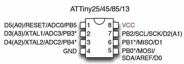
The simplest way to understand how to make the connections is by taking a reference of the pinout of our microcontroller, where the RST, GND, VCC, SCK, MISO, MOSI pins immediately stand out. Only pins 3 and 4 remain free, so we will use these to connect the led and the button.
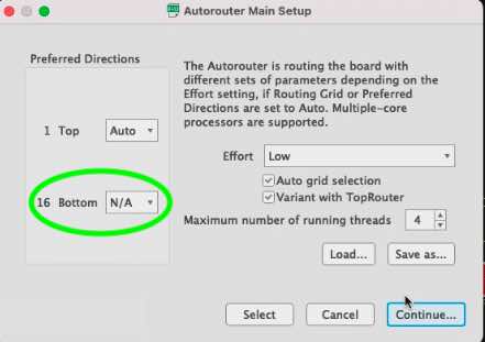
Once the schematic file is finished, we can move on to Board, where we can arrange the components inside the board, choosing the external shape and the path of the tracks. The most difficult part will be to create neat and clean tracks, to do this we will have to move/rotate our components, trying to create as few crossings as possible between the links. It will take several attempts to arrive at an optimal solution, we can also choose whether to proceed with auto-routing or doing the routes manually.
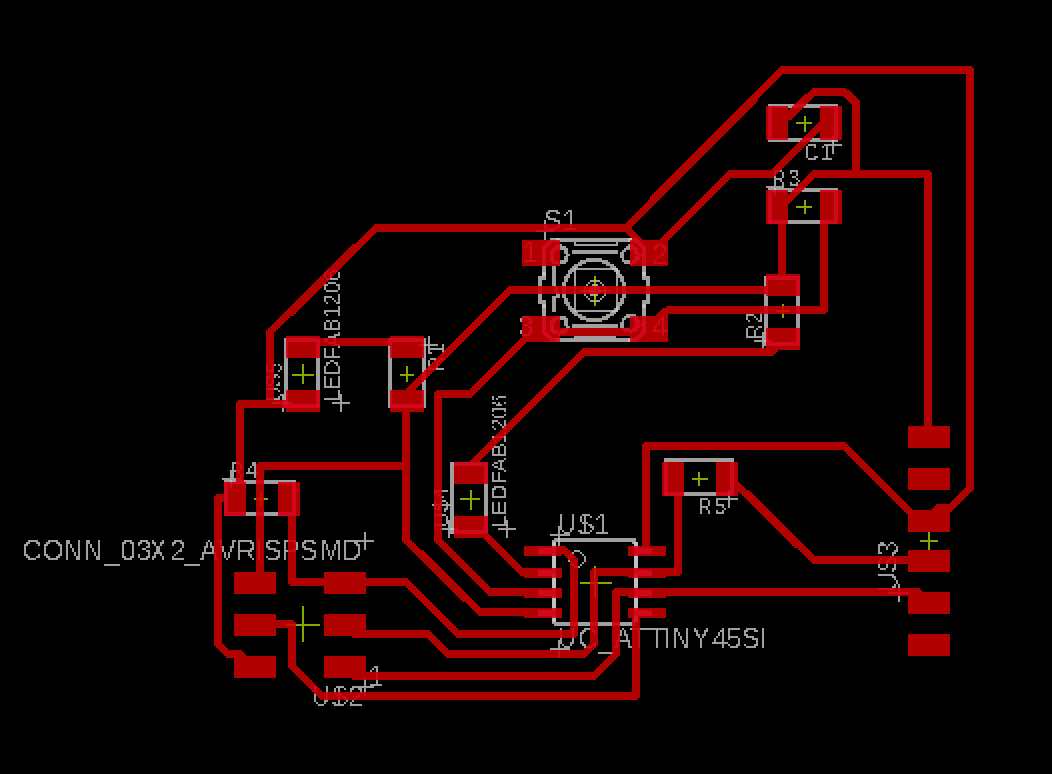
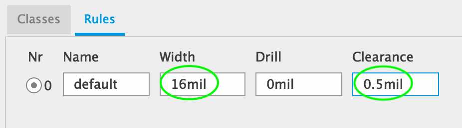
One of the fundamental parts of the Board file are the design rules (width, clearance etc.) essential to obtain a correct and clean output file to be welded.
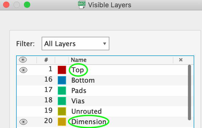
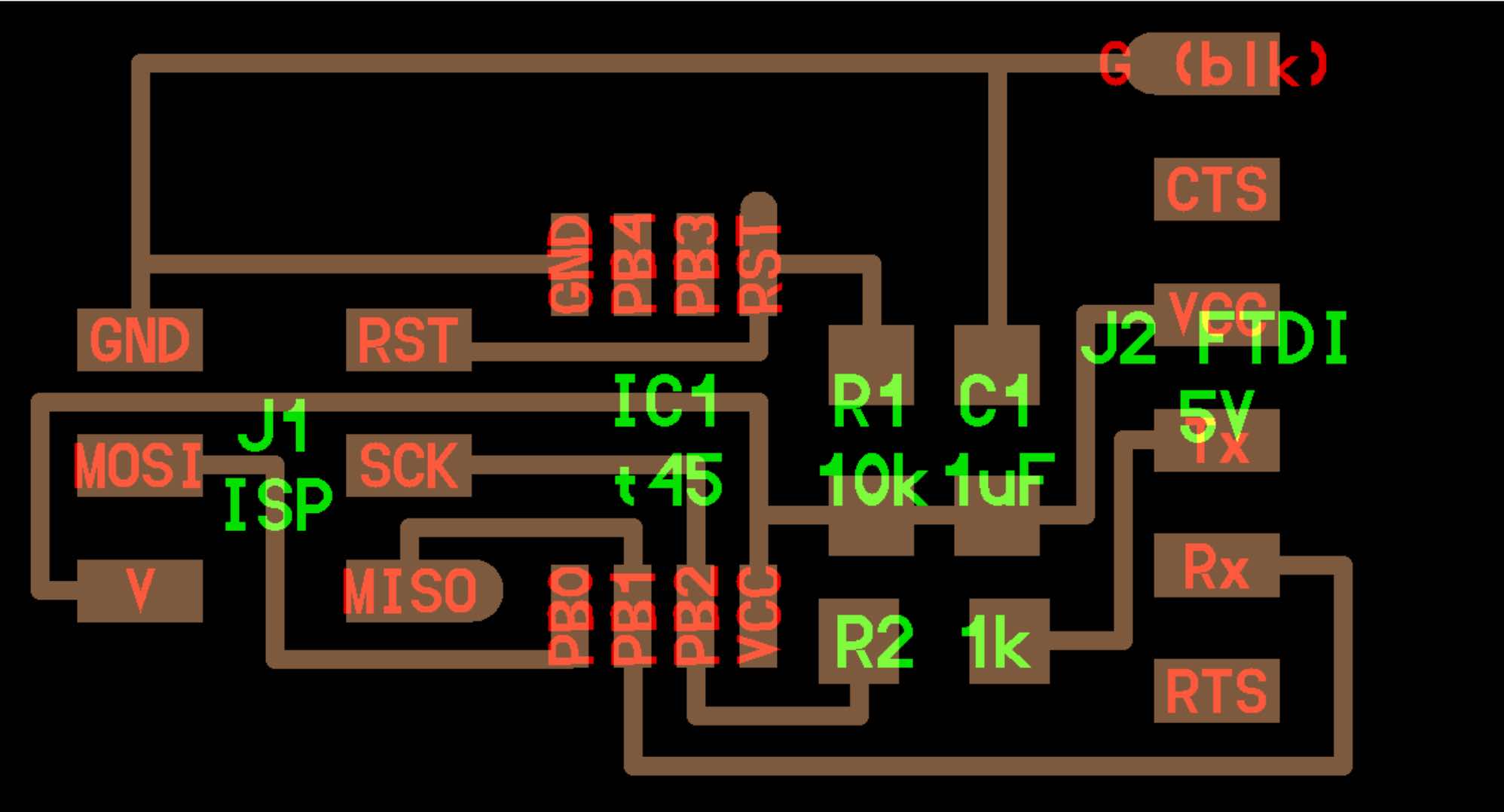
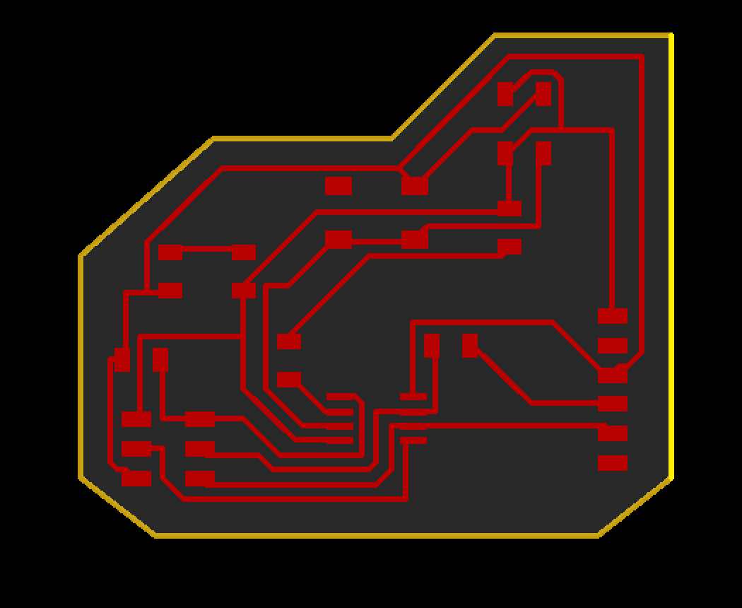
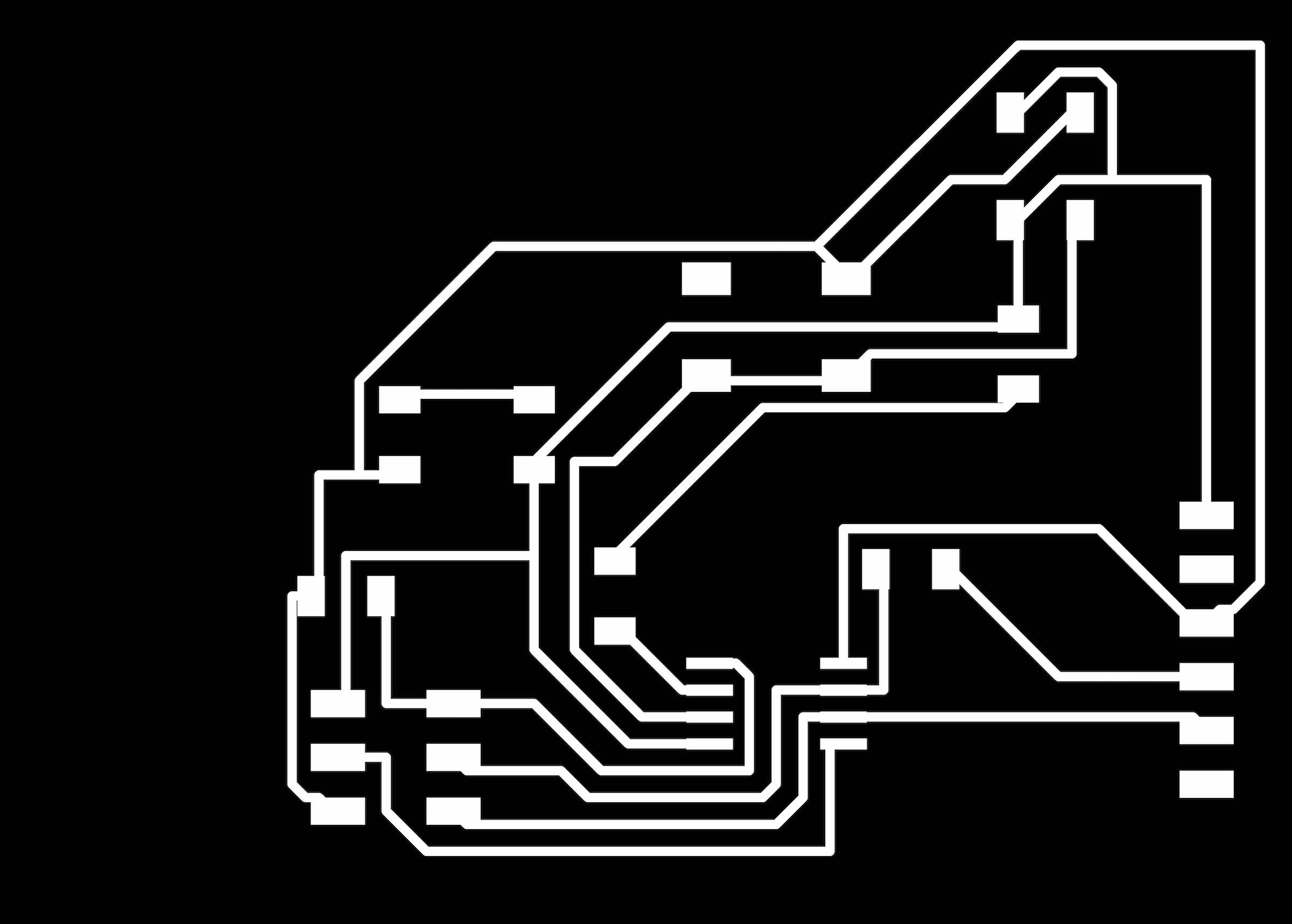
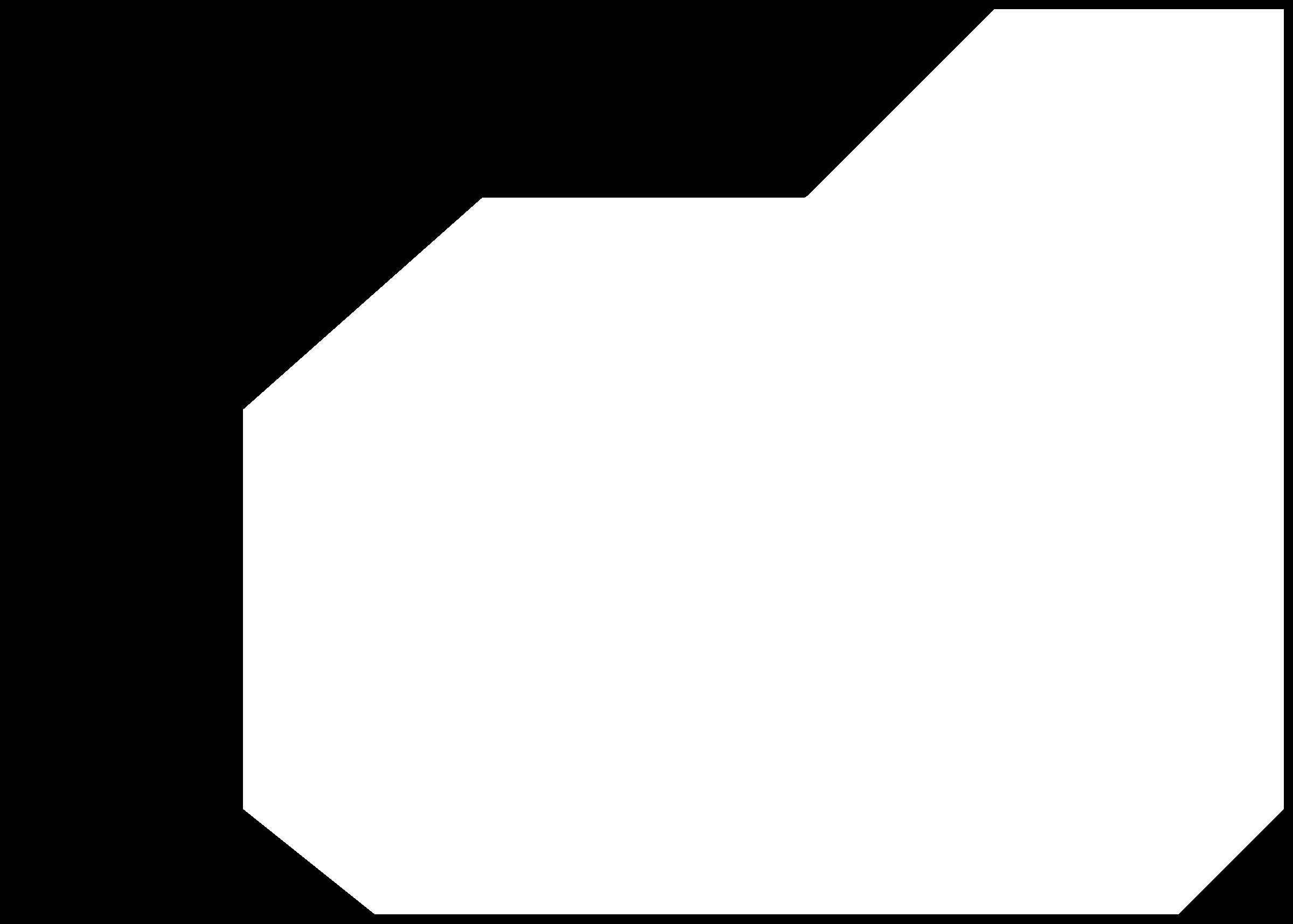
Once the board is drawn and checked, it’s time to export traces and outlines as .png files.
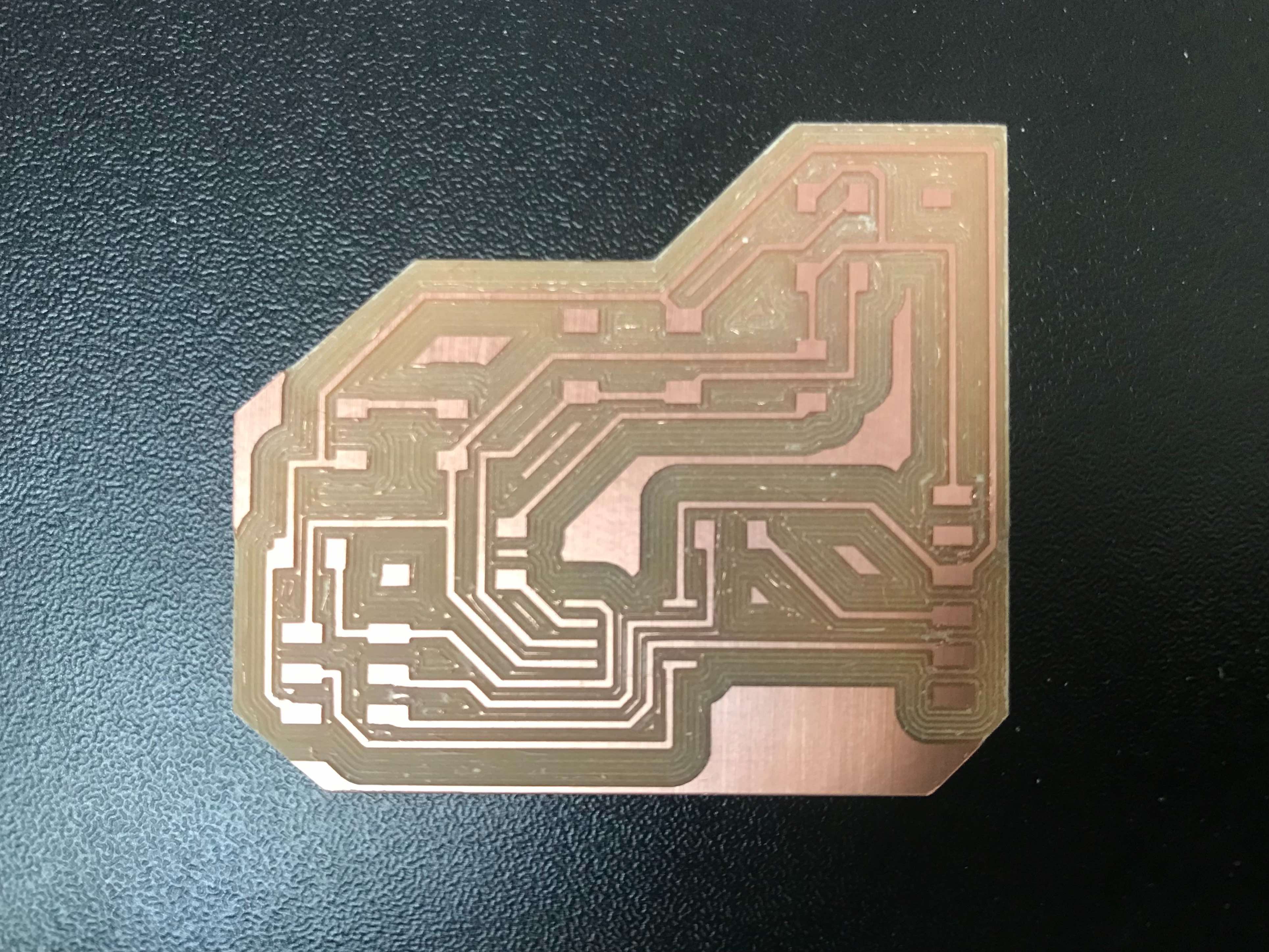
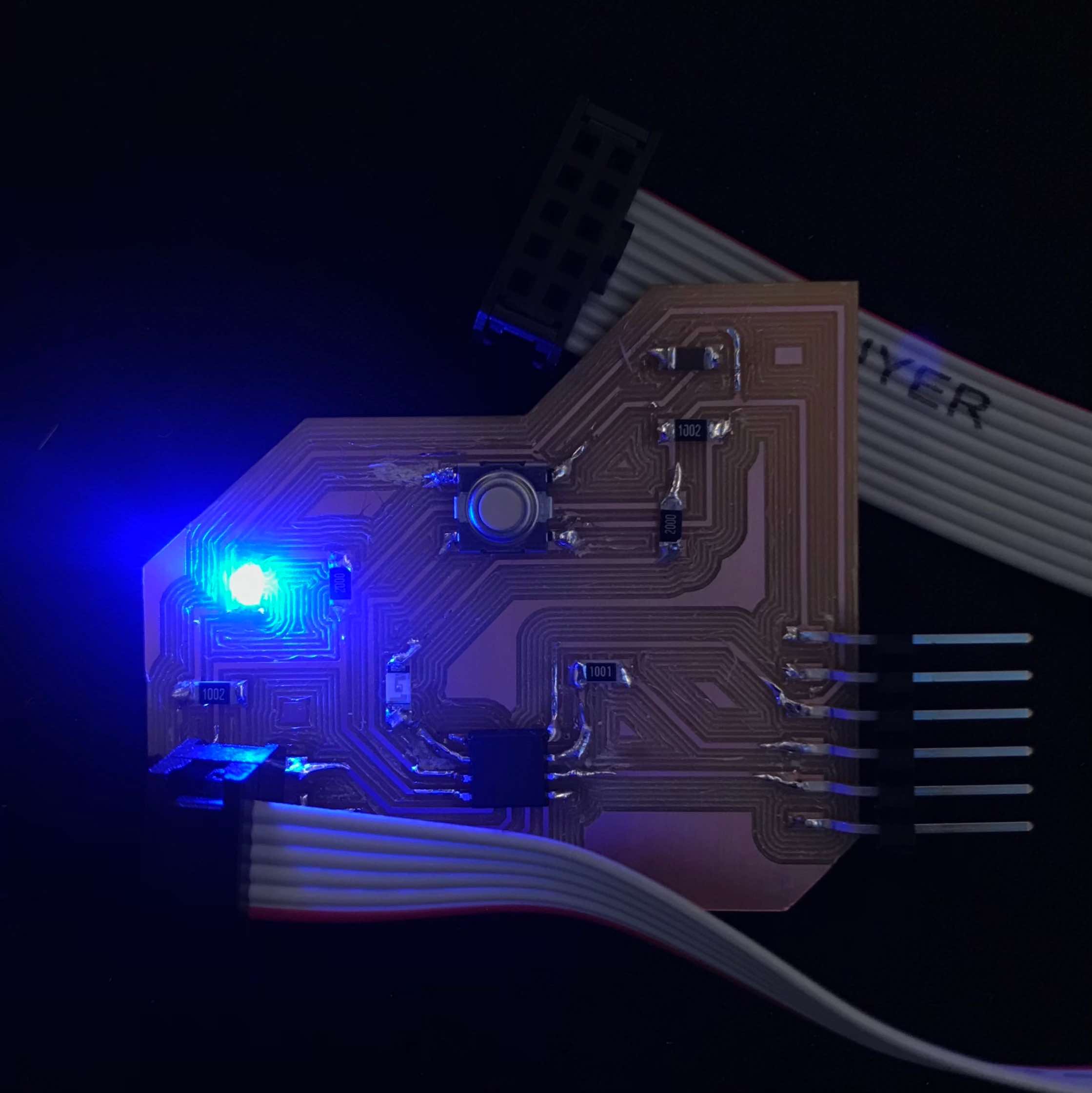
Now that we have our files, as we learned in the past week, we can go to FabModules to create the code for our machine (Roland MDX-40 is recommended, but I used a ShotBot). This is the final result.
Solded.
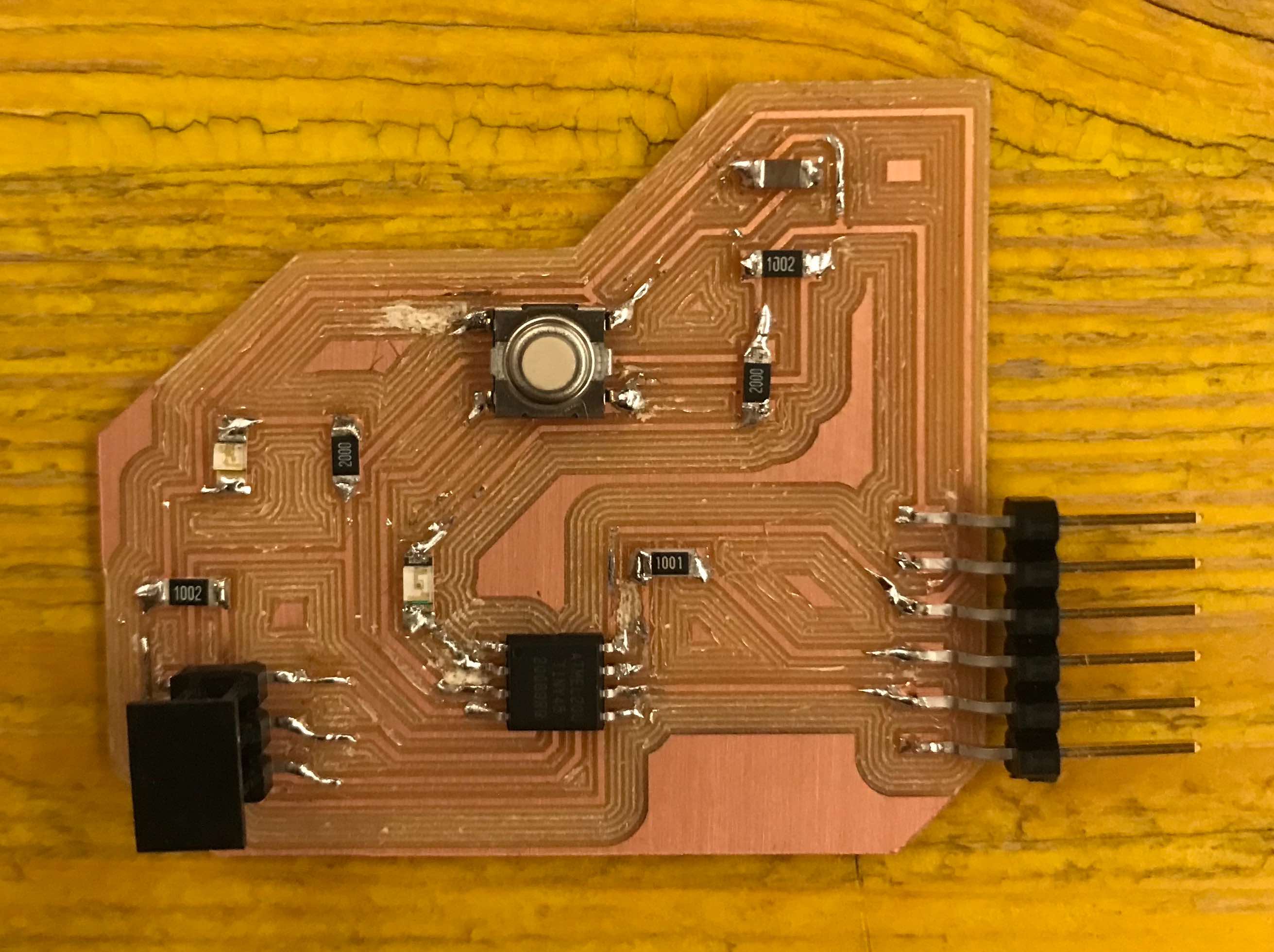
It works!
A FABulous meme for you: