9. Embedded programming
First thing first: download Arduino IDE, which you can do on the official website or from terminal using brew.
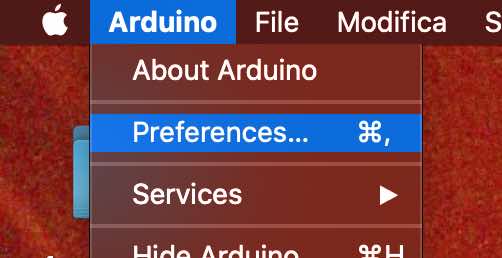
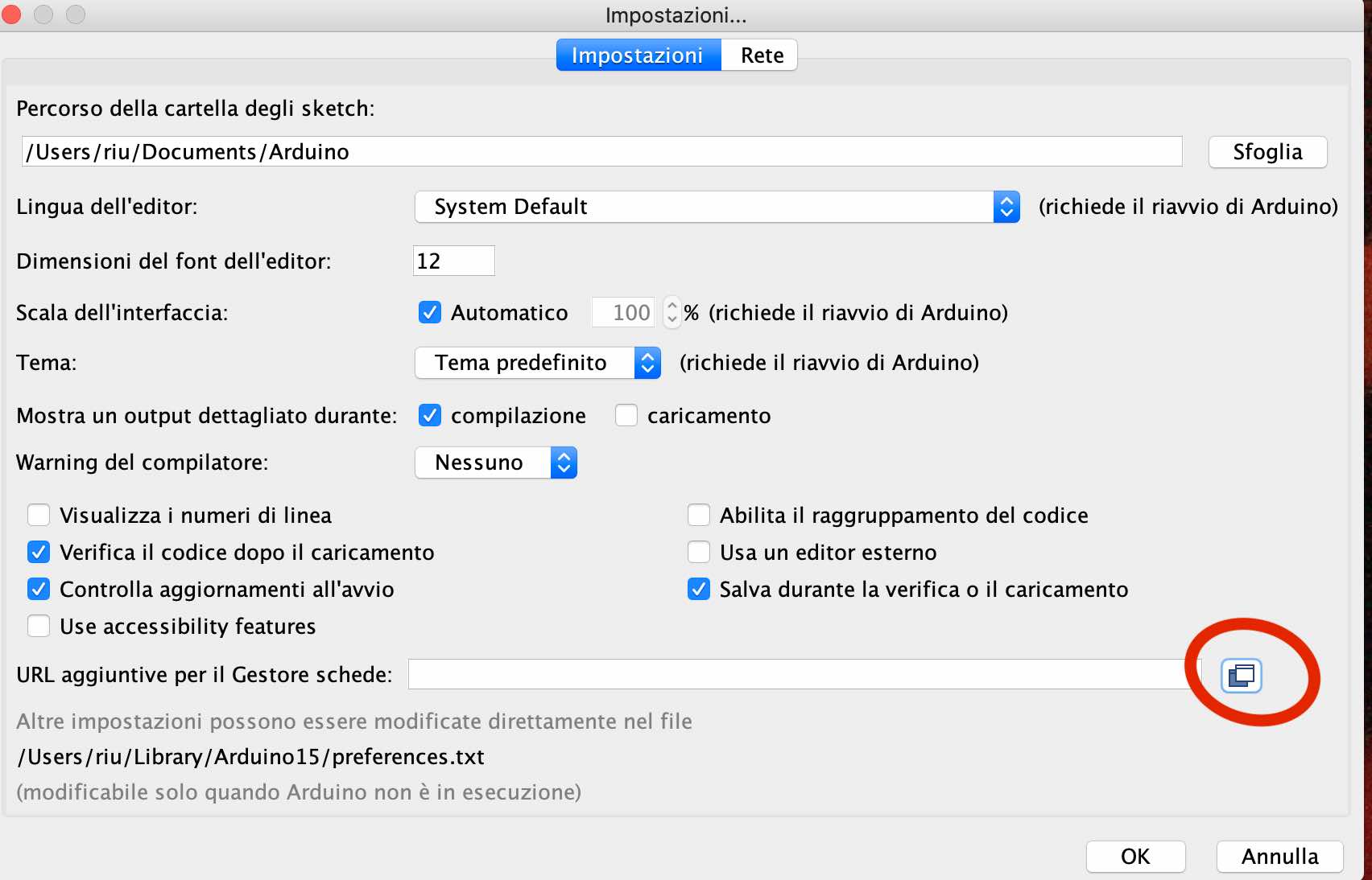
Then go to preferences and copy this link in the space as below.
https://raw.githubusercontent.com/damellis/attiny/ide-1.6.x-boards-manager/package_damellis_attiny_index.json
Click ok and go to tools, selecting “Arduino Uno”.
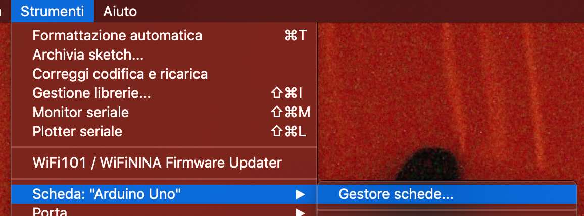
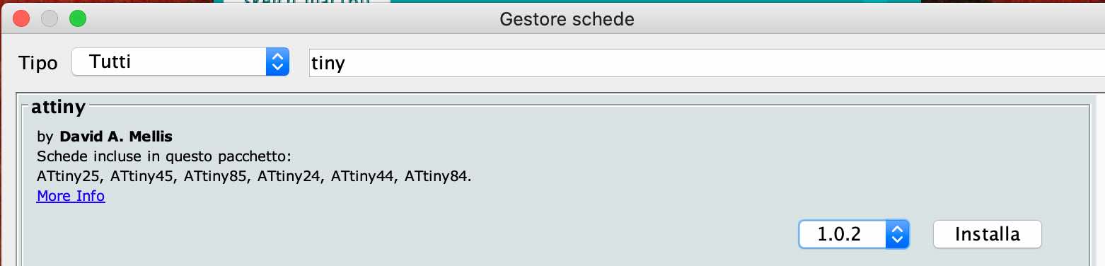
Write down “tiny” to find the library and install it.
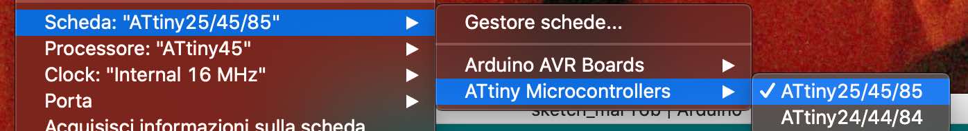
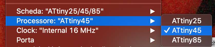
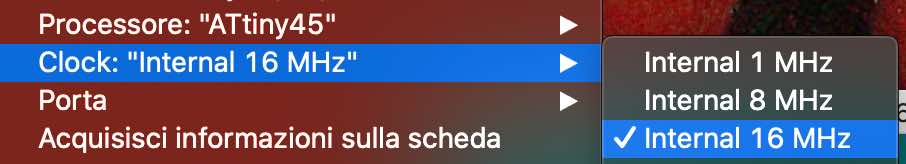
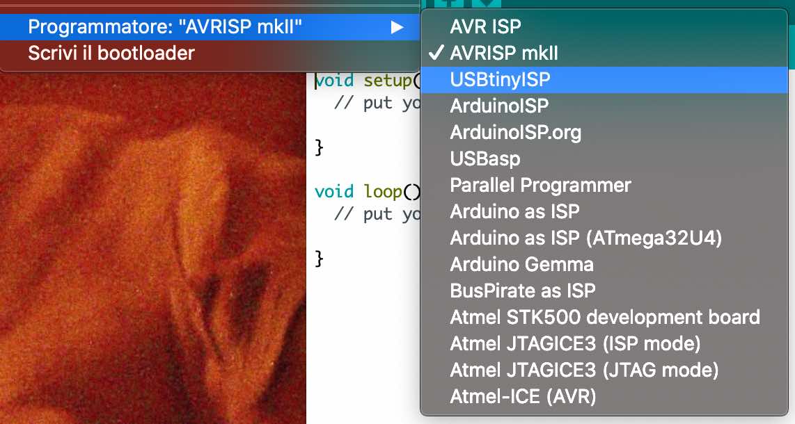
Afterwards, in the tools bar, select the following voices:
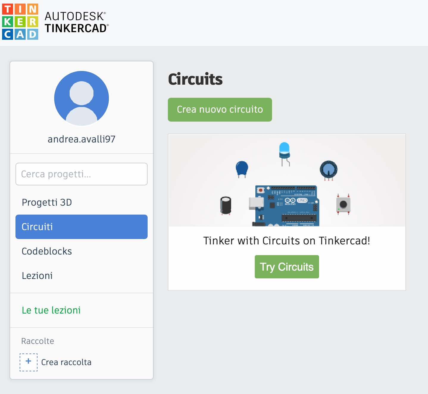
Before using Arduino IDE, I used TinkerCAD to get acquainted with circuits. This program allows you to build circuits by choosing any type of component, also you can simulate the circuit in action, which is very useful to avoid blowing up LEDs (especially for beginners like me). Creating an account is super easy and free, as you can see below.
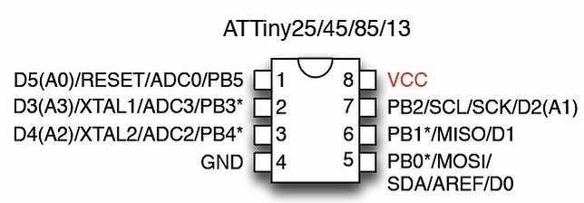
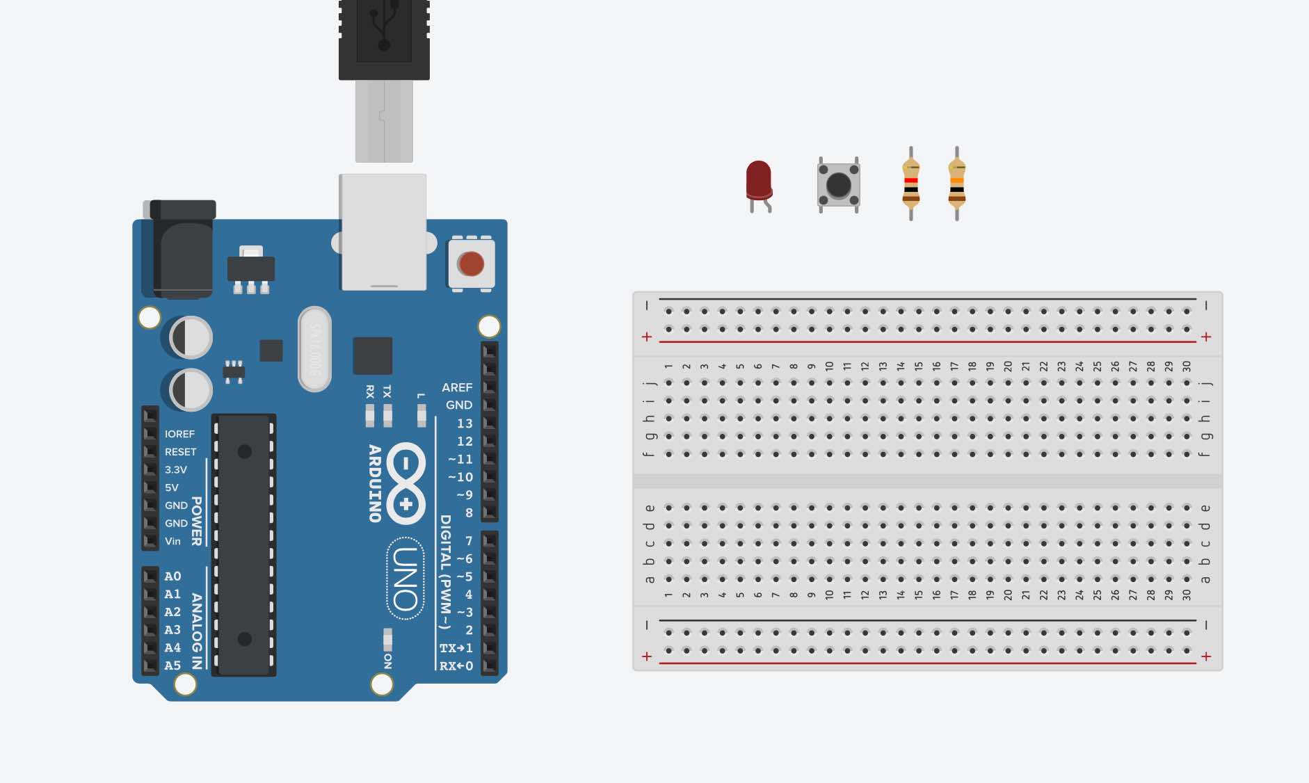
As you can see in the next image, I chose an ArduinoUno, a small breadboard and all the components that we need. Using the breadboard is up to you. To make the connections we’ll use this microcontroller reference:
This is the final circuit. We are going to try two different codes with it.
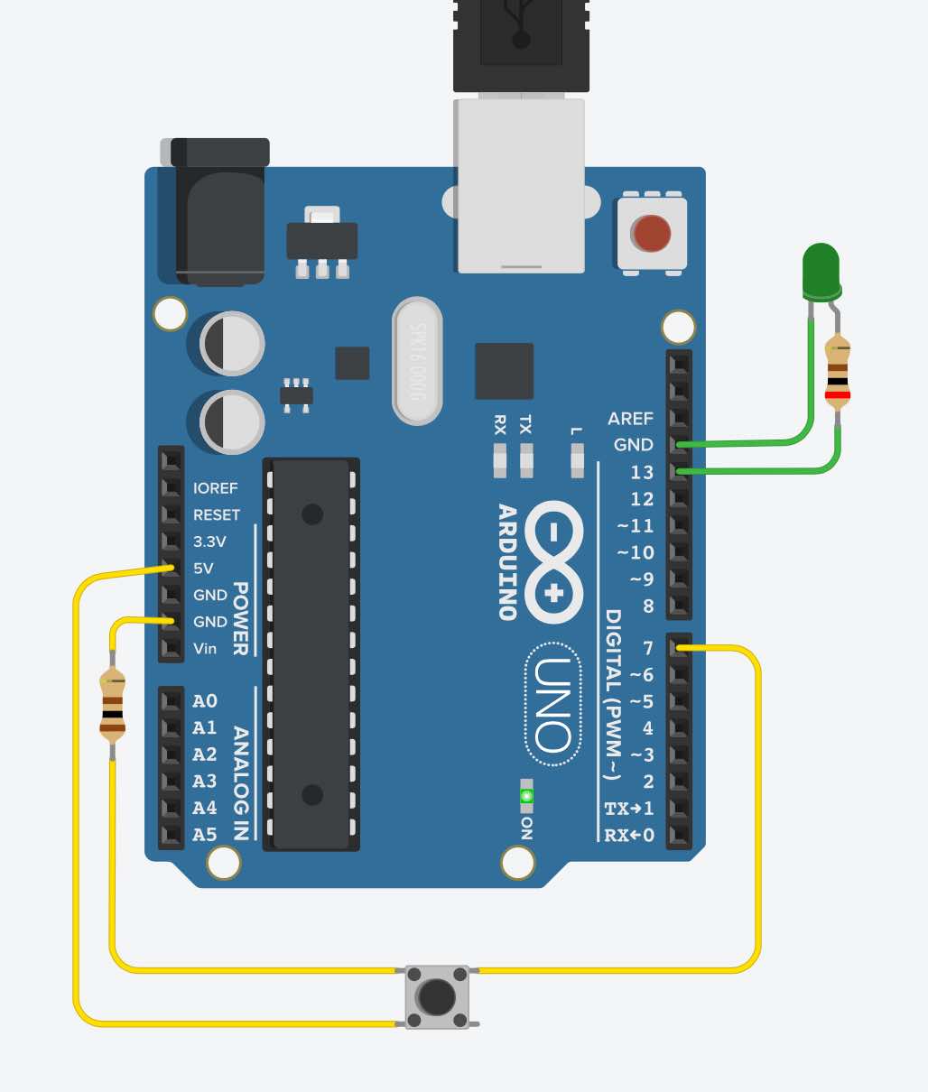
This code below means that we have a led in pin number 13 and a button in pin number 7. The led is our output, because that’s what we see; the button is our input, because we have to press it to make it work. The code loop means that if we press the button, the led will turn on; if we don’t press the button then the led won’t turn on.
int led = 13;
int button = 7;


void setup() {
  pinMode(led, OUTPUT);
  pinMode(button, INPUT);
}

void loop() {
  if (digitalRead(button) == HIGH) {
    digitalWrite(led, HIGH);
    }
  else (digitalRead(button) == LOW); {
    digitalWrite(led, LOW);
  }
}
In this code we will always have the led on, unlike the previous one, but there are two different speeds. If the button is not pressed, the led will light up with a slow speed delay. While if we press the button, the led will light up with a high speed delay.
int led = 13;
int button = 7;
int rate;
const int lowSpeed = 700;
const int highSpeed = 200;

void setup() {
  pinMode(led, OUTPUT);
  pinMode(button, INPUT);
  rate = lowSpeed;
}

void loop() {
  if(digitalRead(button)) {
    rate = highSpeed;
  } else {
    rate = lowSpeed;
  }
  digitalWrite(led, !digitalRead(led));
  delay(rate);
}
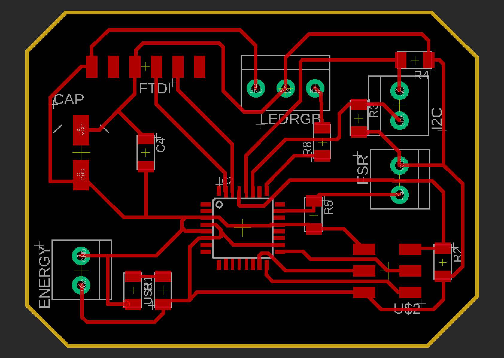
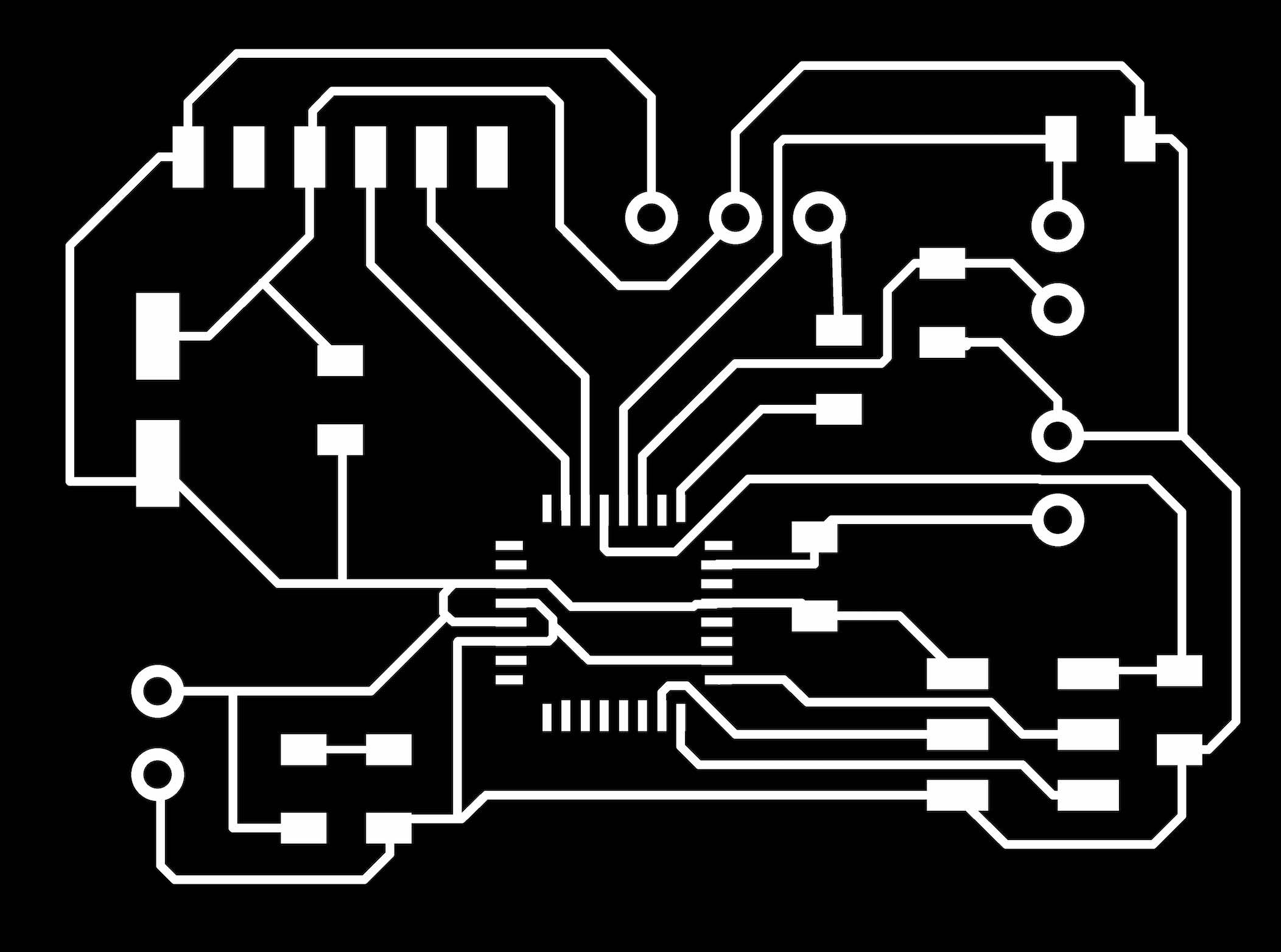
Since my old board wasn’t working anymore, I decided to mill a new one, with the purpose to use it for this assignment and also input and output devices’ assignments. It’s a pleasure to introduce you to megaboard! The microcontroller I’m going to use is a ATmega 328. Here you see the pinout:
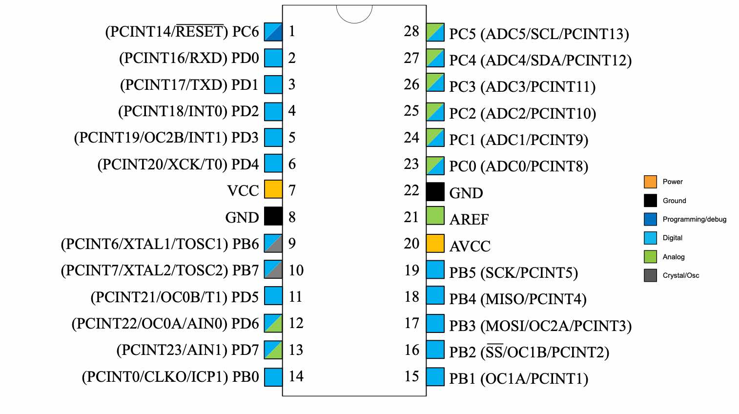
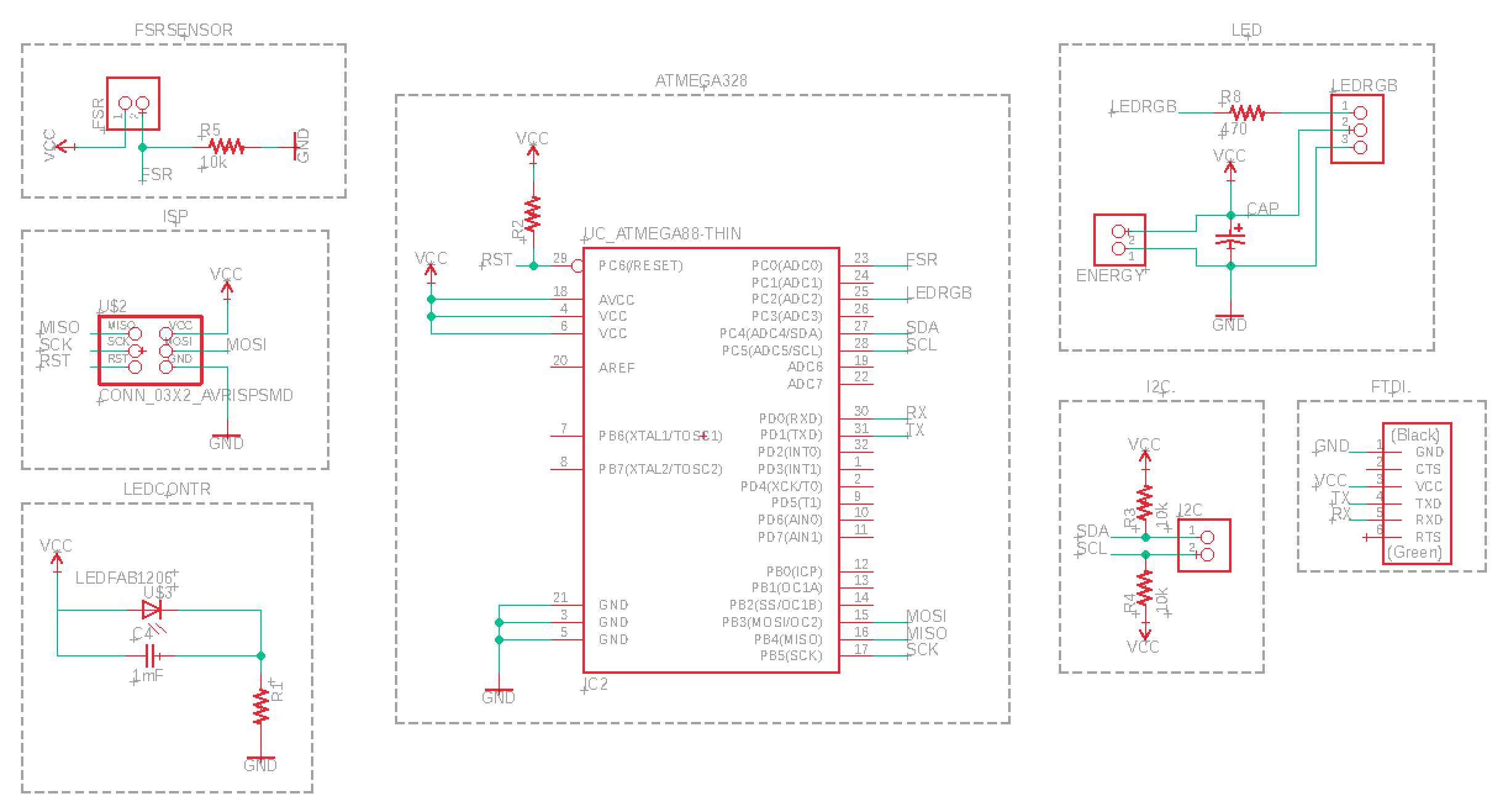
As you can see it has different connectors to make it easy to program it, add a power supply, a led string (Output Devices) and a FSR sensor (Input Devices).

We just have to solder the components and start to program!
And when you think that everything is going in the right direction, a message arrives, the only one you don’t want to read, two letters and a number, the most fearful:
rc = -1
Let’s start over. Again.
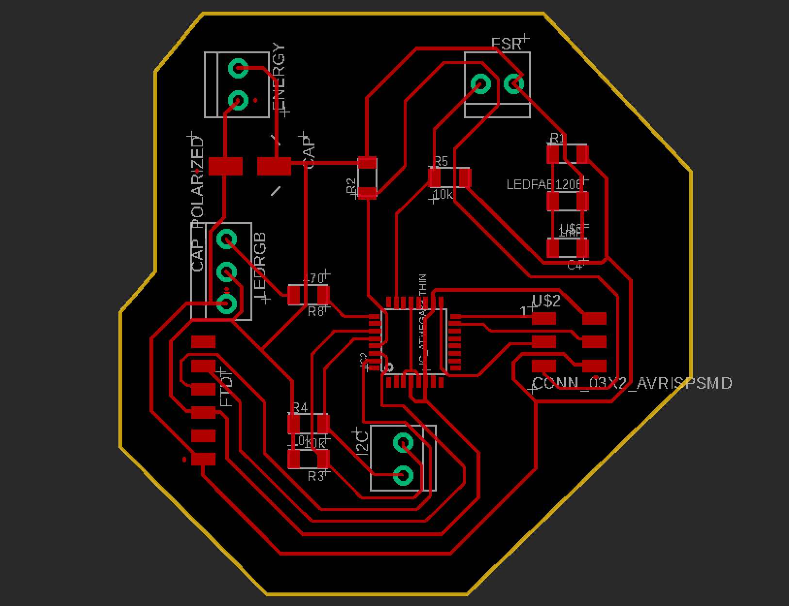
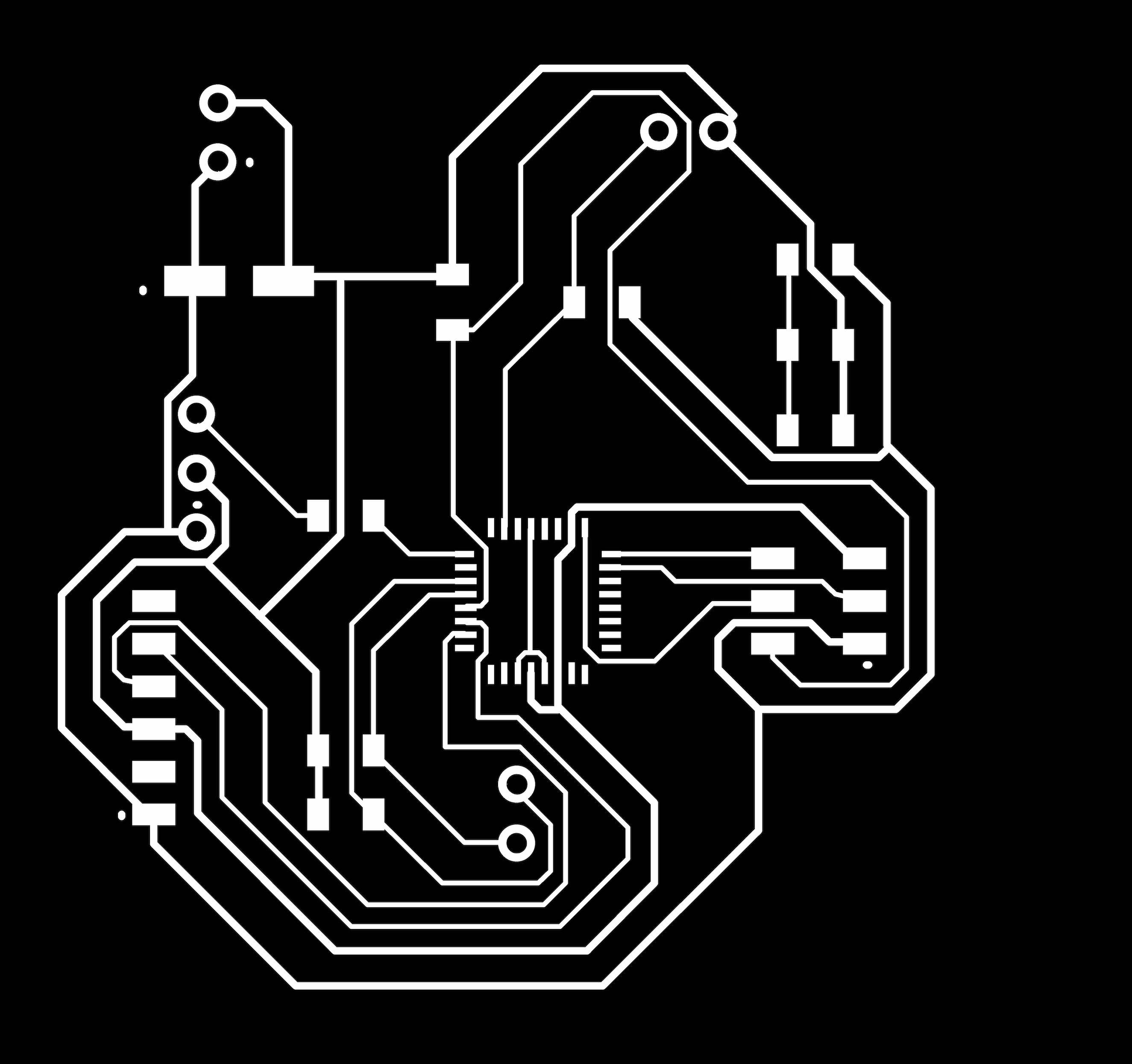
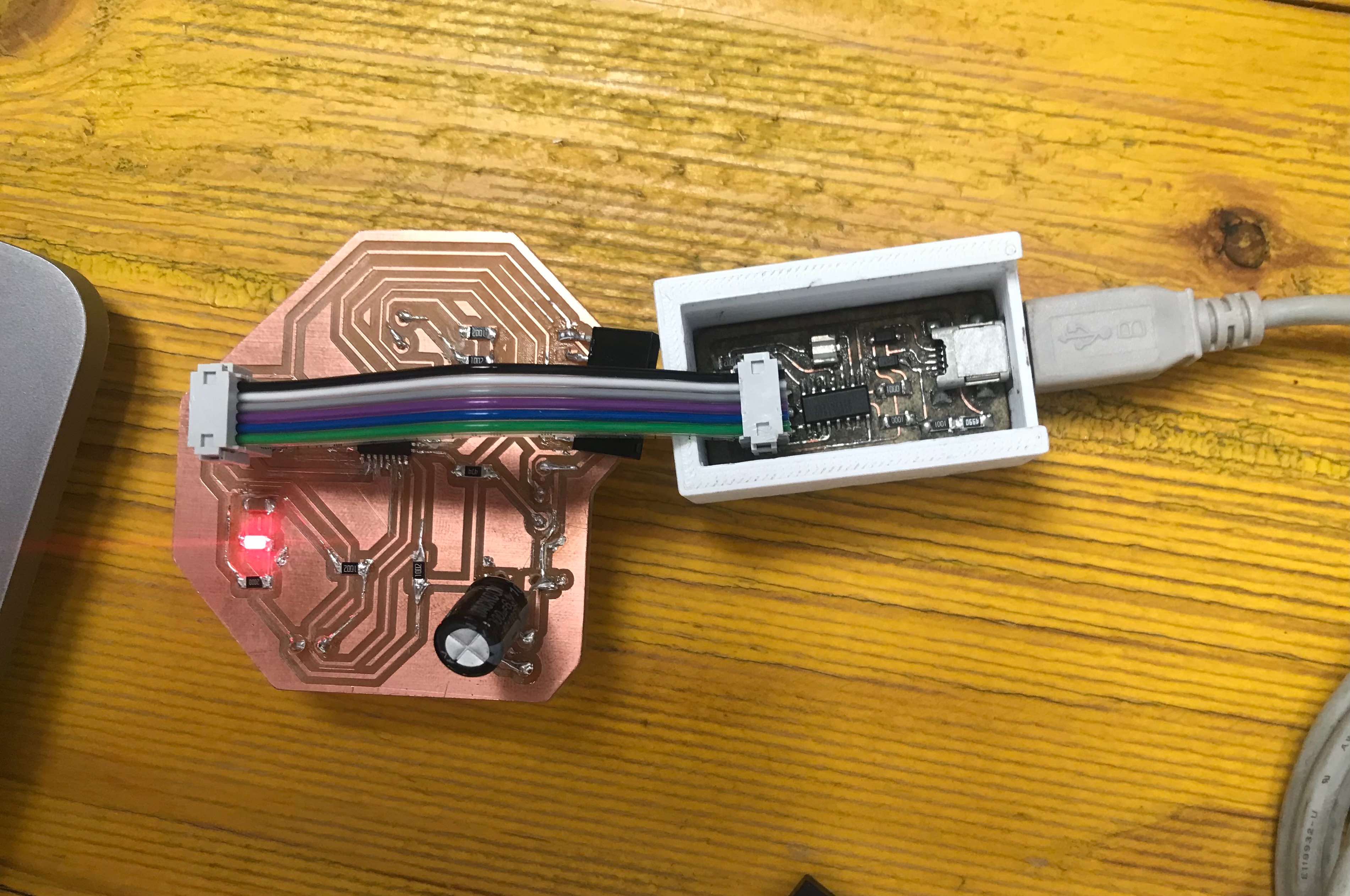
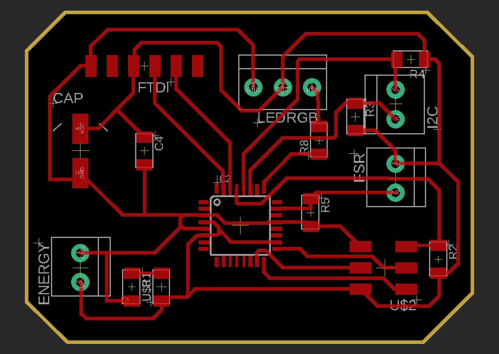
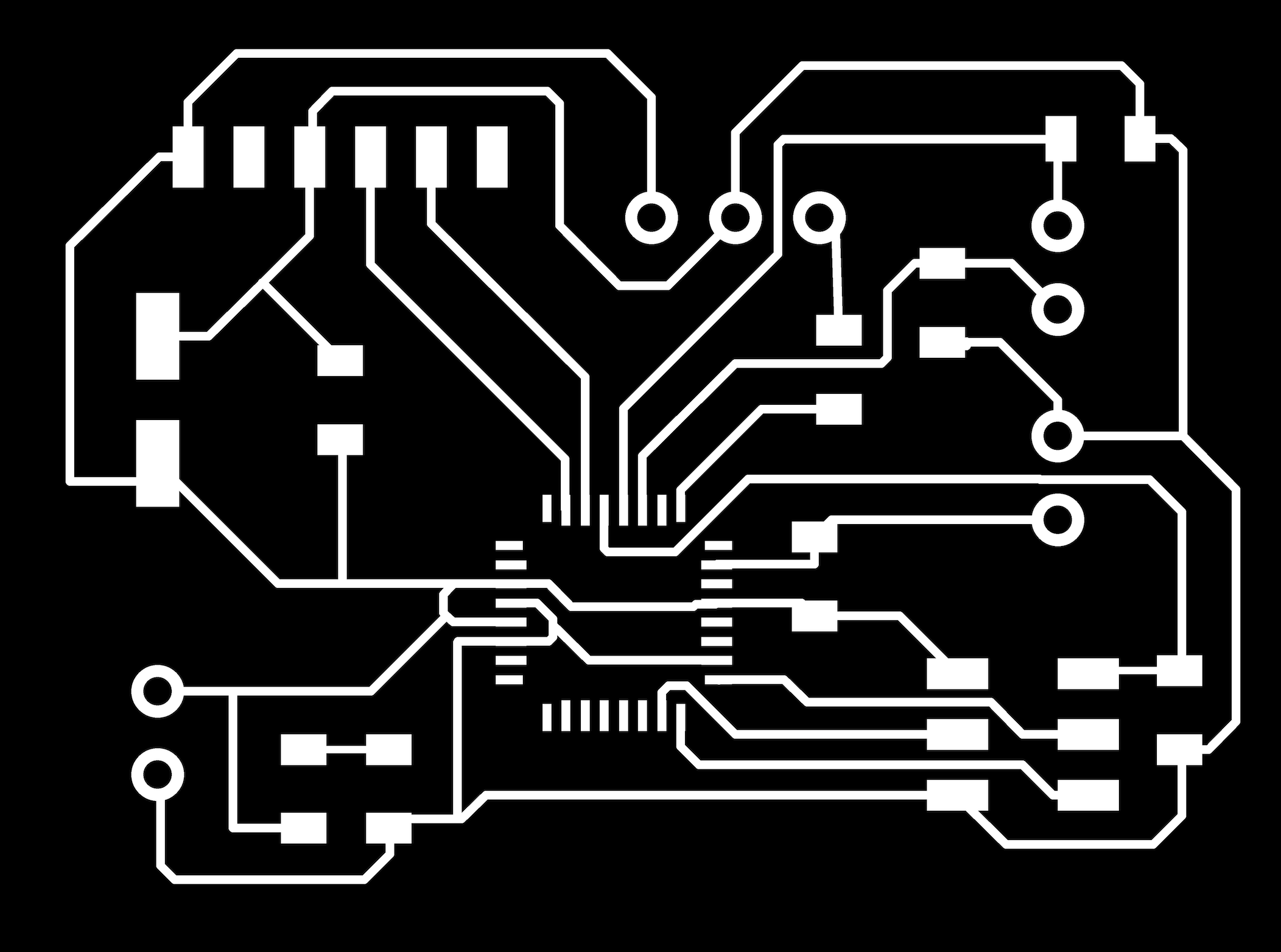
Since I tried to mill the same board for 3 times, and everytime I had the same answer, I decided to edit it on Eagle, so this is megabord 2.0.

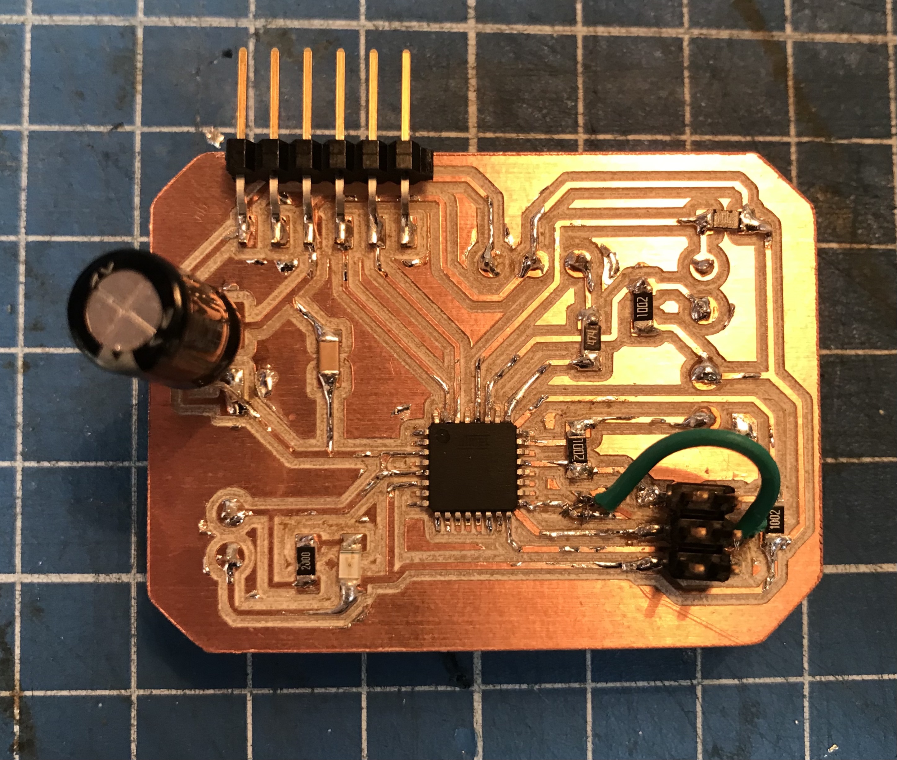
Let’s sold it to see if it works (fingers crossed!).
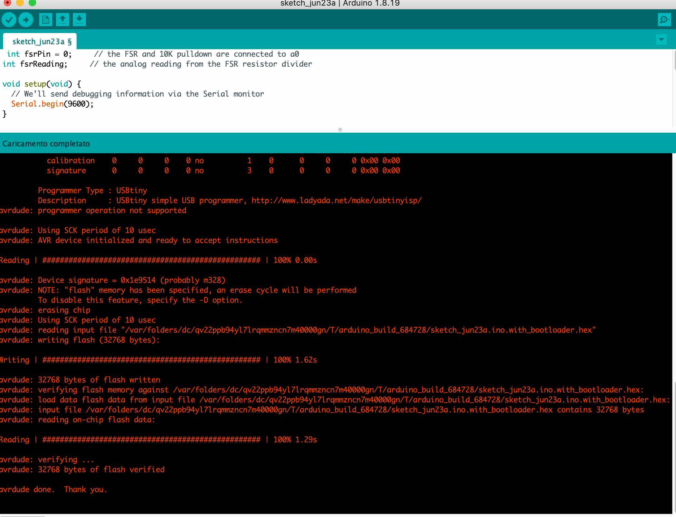
Now we are going to connect it as before and pray. The code I’m using is the one for the FSR sensor in the input assignment.
 int fsrPin = 0;     // the FSR and 10K pulldown are connected to a0
int fsrReading;     // the analog reading from the FSR resistor divider

void setup(void) {
  // We'll send debugging information via the Serial monitor
  Serial.begin(9600);
}

void loop(void) {
  fsrReading = analogRead(fsrPin);

  Serial.print("Analog reading = ");
  Serial.print(fsrReading);     // the raw analog reading

  // We'll have a few threshholds, qualitatively determined
  if (fsrReading < 10) {
    Serial.println(" - No pressure");
  } else if (fsrReading < 200) {
    Serial.println(" - Light touch");
  } else if (fsrReading < 500) {
    Serial.println(" - Light squeeze");
  } else if (fsrReading < 800) {
    Serial.println(" - Medium squeeze");
  } else {
    Serial.println(" - Big squeeze");
  }
  delay(1000);
}
To be able to program it you have to add this library:
https://mcudude.github.io/MiniCore/package_MCUdude_MiniCore_index.json
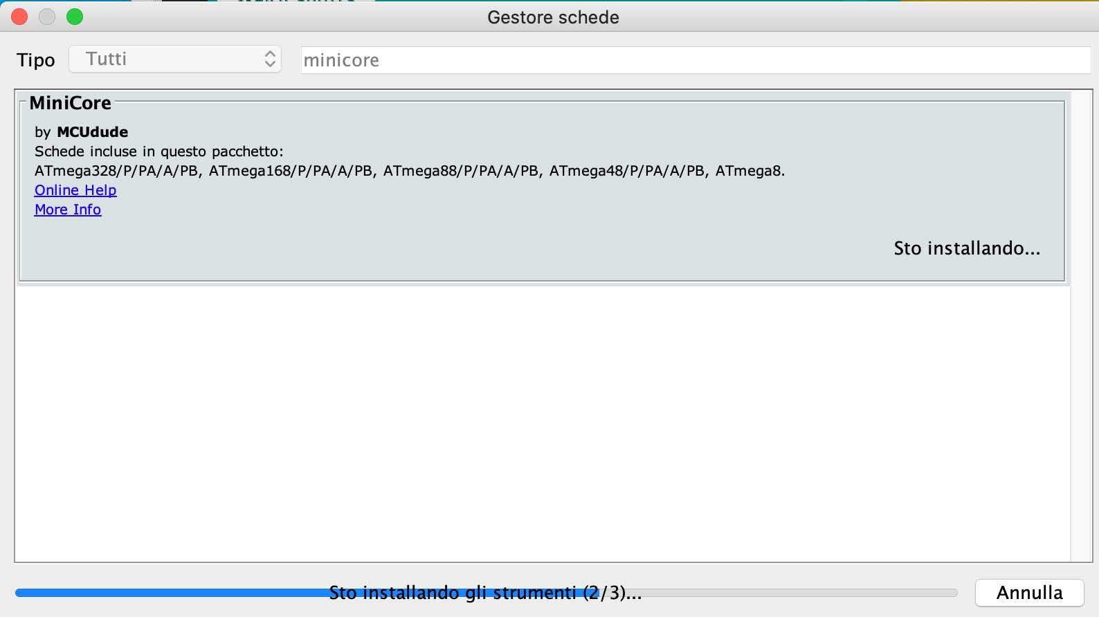
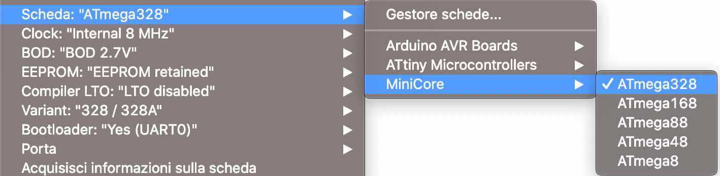
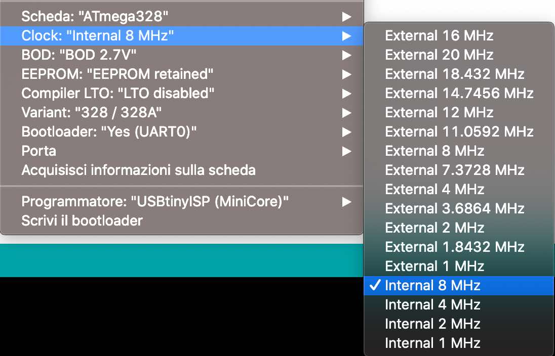
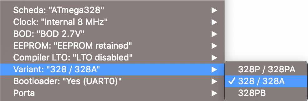
After the installation we have to edit some settings as you can see in the following pictures.
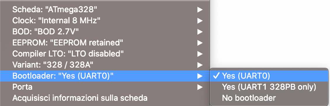
I AM GLAD TO TELL YOU THAT IT FINALLY WORKED!
The things that gave me the most problems were:
-
ISP: as you can see in the photo above I had to create a bridge (my instructor helped me with that) because a track under the ISP was skipped
-
I kept selecting the wrong port on Arduino IDE, so obviously it didn’t read the programmer
-
I think my USB adapter is breaking, because sometimes it doesn’t work, other times it does
silent meme