14. Networking and communications
This week I worked on one of the objects of the final project. Since it’s a device which has to communicate with other devices, my instructor suggested to work with a ESP32.
ESP32 is a low-cost, low-power system-on-chip (SoC) microcontroller series with built-in dual-mode Wi-Fi and Bluetooth created by Espressif Systems. As a low cost Wi-Fi / Bluetooth combo radio, it has gained popularity not only among hobbyists but also among IoT developers. Its low power consumption, the multiple open-source development environments and the libraries available make it perfectly suitable for any type of developer.
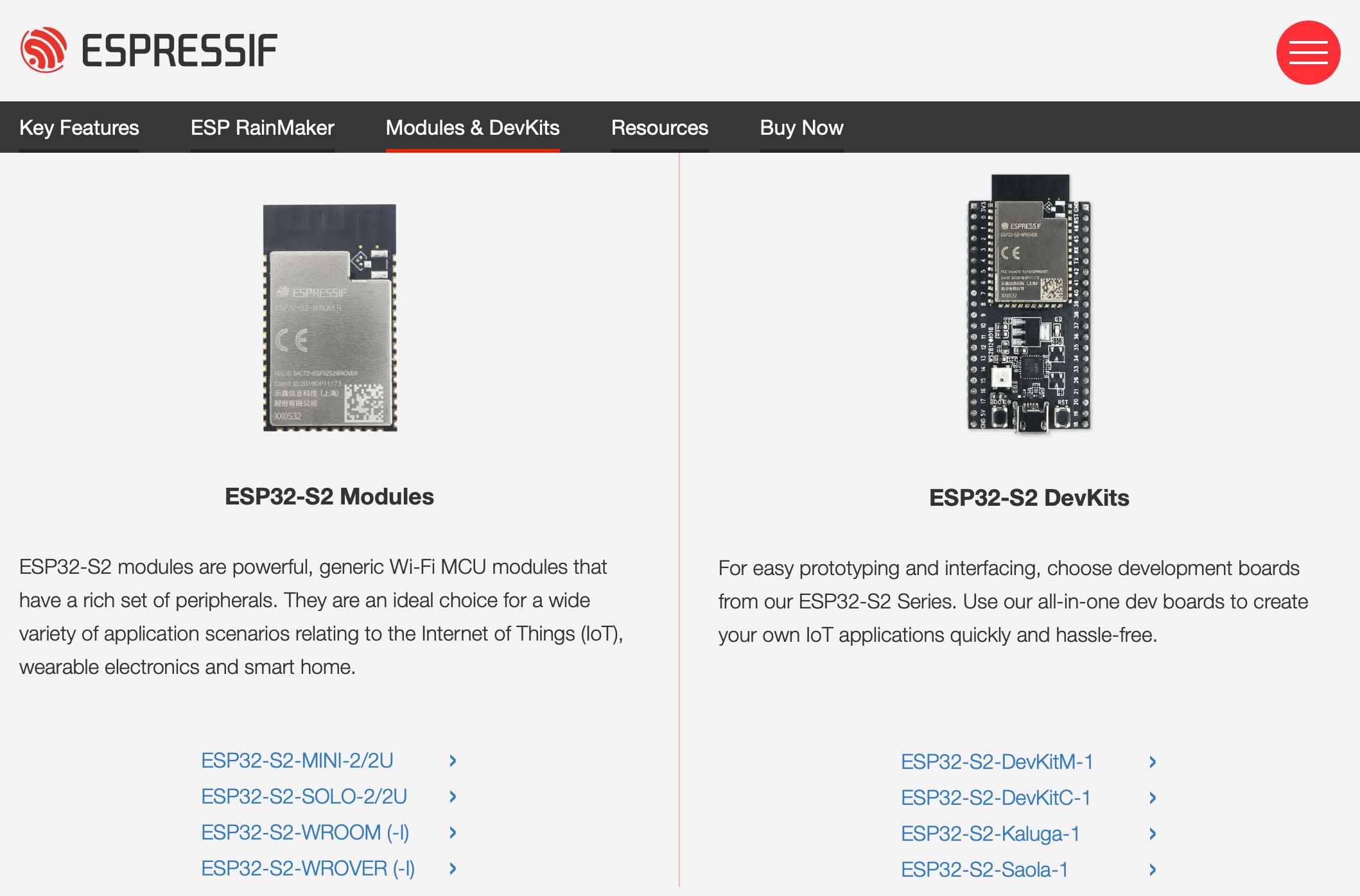
However, ESP32 is available in so many modules and development boards that it may be difficult to choose the right product. We will focus on S2 ones, which can be divided as you can see in the picture. We’ll start by using a DevKit so that we can see how it works.
To see how it works, we tried to upload a program in Arduino IDE, to do that we must add the specific library. You can copy and past the following link:
https://raw.githubusercontent.com/espressif/arduino-esp32/gh-pages/package_esp32_dev_index.json

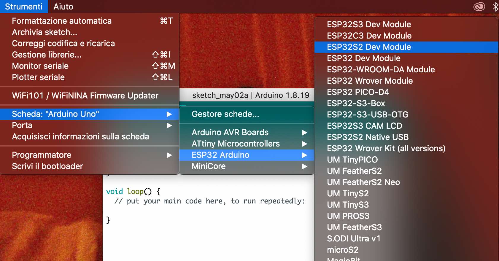
Now we can adjust the features to start programming properly.
This is the code we have used:
#include "WiFi.h"
String wifiSSID;
String wifiPass;
void setup() {
  Serial.begin(115200);
  delay(200); // just a delay to let everything be set in place
  WiFiSetup();
}
void loop() {
}

void WiFiSetup() {
  WiFi.mode(WIFI_STA);
  if (wifiSSID == "") {
    // Scan wifi networks
    Serial.println("\nLooking for WiFi networks\n");
    int n = WiFi.scanNetworks();
    if (n == 0) {
      Serial.println("No networks found");
      return;
    }
    Serial.print(n);
    Serial.println(" networks found:\n");
    for (int i = 0; i < n; ++i) {
      Serial.print(i + 1);
      Serial.print(": ");
      Serial.println(WiFi.SSID(i));
    }

// Choose SSID by number
Serial.print("\n\nChoose the network by typing its number: ");

while (!Serial.available()) {}

int c = Serial.read() - 48; // this doesn't work with numbers bigger that 9!

while (Serial.read() != -1) {}

Serial.println(c);

wifiSSID = WiFi.SSID(c-1);
Serial.print('\n');
Serial.println(wifiSSID);
Serial.print('\n');
if (wifiPass.length() == 0) {
  // Ask for password
  Serial.print("Type the password: ");
  bool endChar = false;
  while (!endChar) {
    if (Serial.available()) {
      if (Serial.peek() == 13) {
        endChar = true;
        Serial.println();
      } else {
        wifiPass += static_cast<char>(Serial.read());
        Serial.print('*');
      }
    }
  }
}
  }
  Serial.print('\n');
  Serial.println("Connecting to WiFi...");
  WiFi.begin(&wifiSSID[0], &wifiPass[0]);
  while (WiFi.status() != WL_CONNECTED) {
    delay(1000);
    Serial.println("Connecting to WiFi...");
  }
  Serial.println("\nConnected\n");
  Serial.print("IP address: ");
  Serial.println(WiFi.localIP());
}
Also remember to change this value in the serial monitor section!

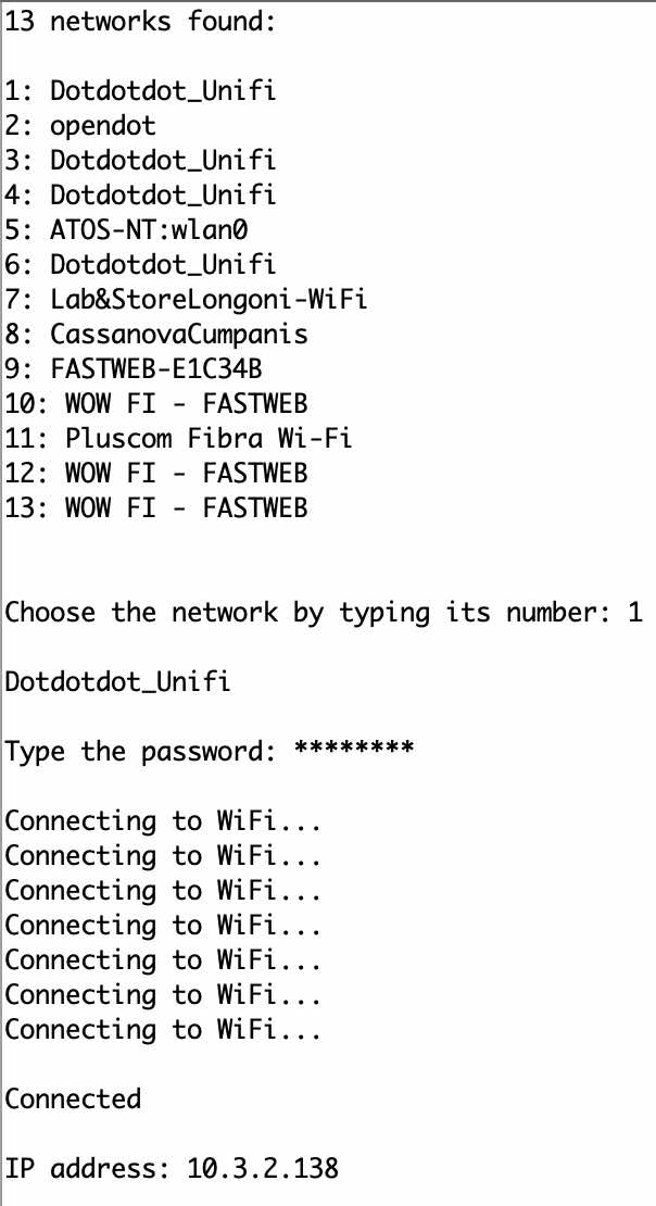
As we can see in the monitor, the program is asking me to choose the wifi connection and the password. It works!
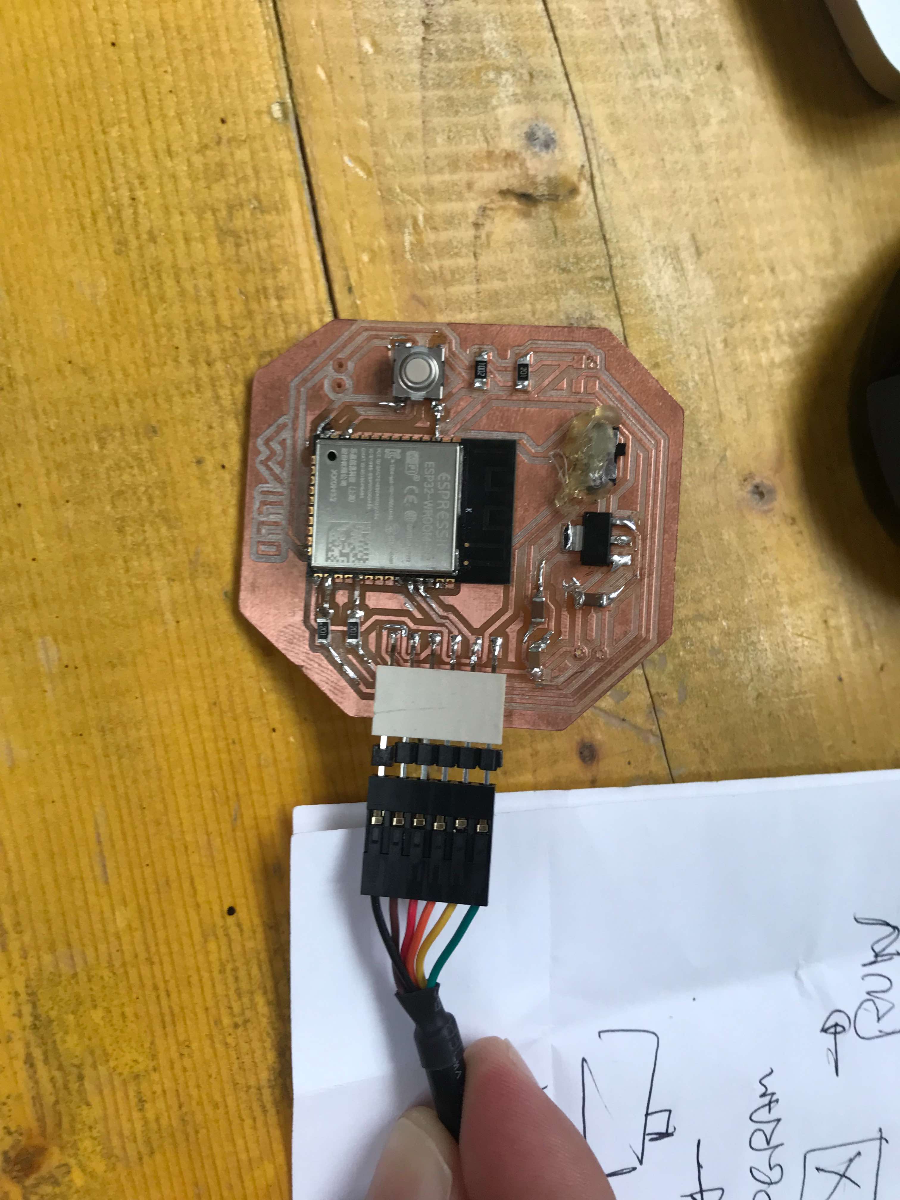
Now we can work using a processor on the board for the final project. We are going to use a ESP32-WROOM-32.
As board we are going to use the one of Willo, whose details you can find on the final project page. Here is the welded board, we are ready to program our ESP32.
This is the code we are going to try. Once we have defined the variables, we can initialize the serial communication (void.setup). The wording led.routine is used to turn the led on and off cyclically. Touch sensor average is used to calibrate the pin, in fact the pin will be read more than 10 times to make an average (baseline). In void.loop I declare the touch variable and use it both to compare it with the baseline value and to send a message to the serial monitor.
// #define WIFI

#ifdef WIFI
#include "WiFi.h"
#endif

// Capacitive touch sensor pin
#define TOUCH_PIN 12

// RGB LED pins
#define LED_R 24
#define LED_G 26
#define LED_B 29

// wifi setup
String wifiSSID = "";
String wifiPass = "";

int touchBaseline;

void setup() {
  Serial.begin(115200);
  Serial.println("Sketch start");

  // LED setup
  pinMode(LED_R, OUTPUT);
  pinMode(LED_G, OUTPUT);
  pinMode(LED_B, OUTPUT);
  ledRoutine();

  // Touch sensor average baseline setup
  int accumulator = 0;
  int n = 10;
  for (short i = 0; i < n; i++) {
    accumulator += touchRead(TOUCH_PIN);
  }
  touchBaseline = accumulator / n;
  Serial.print("baseline: ");
  Serial.println(touchBaseline);

  #ifdef WIFI
  // Connect to wi-fi
  WiFi.mode(WIFI_STA);
  Serial.print('\n');
  Serial.println("Connecting to WiFi...");
  WiFi.begin(&wifiSSID[0], &wifiPass[0]);
  while (WiFi.status() != WL_CONNECTED) {
    delay(1000);
    Serial.println("... nothing yet ...");
  }
  Serial.println("Connected");
  Serial.print("IP address: ");
  Serial.println(WiFi.localIP());
  #endif
}

void loop() {

 int touch = touchRead(TOUCH_PIN);
 if (touch < touchBaseline) {
    Serial.println("Touch sensor activated");
    Serial.println(touch);
    delay(200);
    //ledRoutine();
  }
}

void ledRoutine() {
  for (short i = 0; i < 3; i++) {
    digitalWrite(LED_R, LOW);
    digitalWrite(LED_G, LOW);
    digitalWrite(LED_B, LOW);
    delay(50);
    digitalWrite(LED_R, HIGH);
    delay(50);
    digitalWrite(LED_G, HIGH);
    delay(50);
    digitalWrite(LED_B, HIGH);
    delay(100);
  }
  digitalWrite(LED_R, LOW);
  digitalWrite(LED_G, LOW);
  digitalWrite(LED_B, LOW);
}
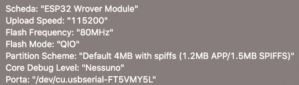
Once we have selected all the different settings:
We are ready to upload our code:
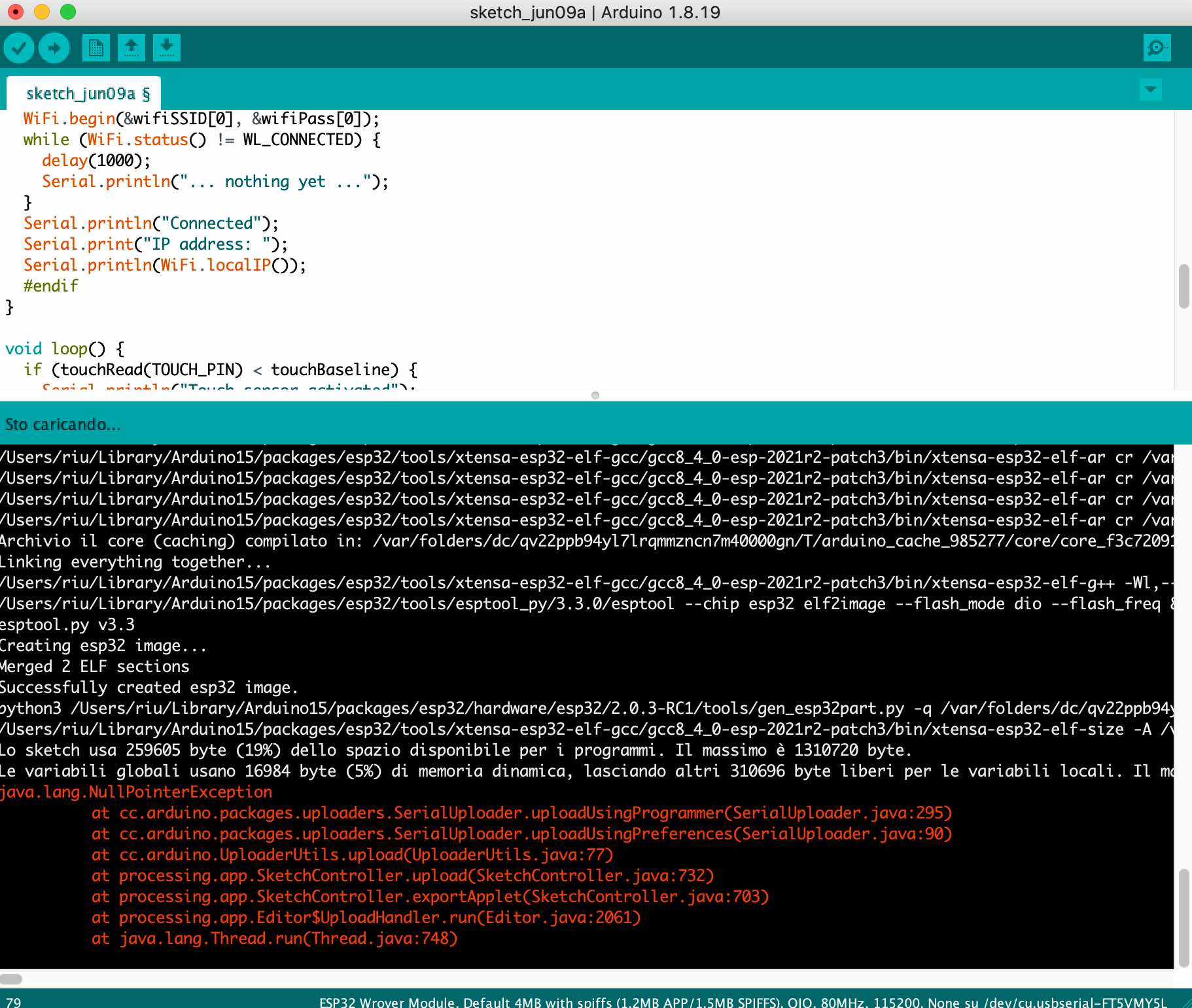
And hope this is the final response:

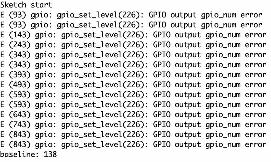
Now we can go to our serial monitor, turn off the switch, click reset and the calibration will start.
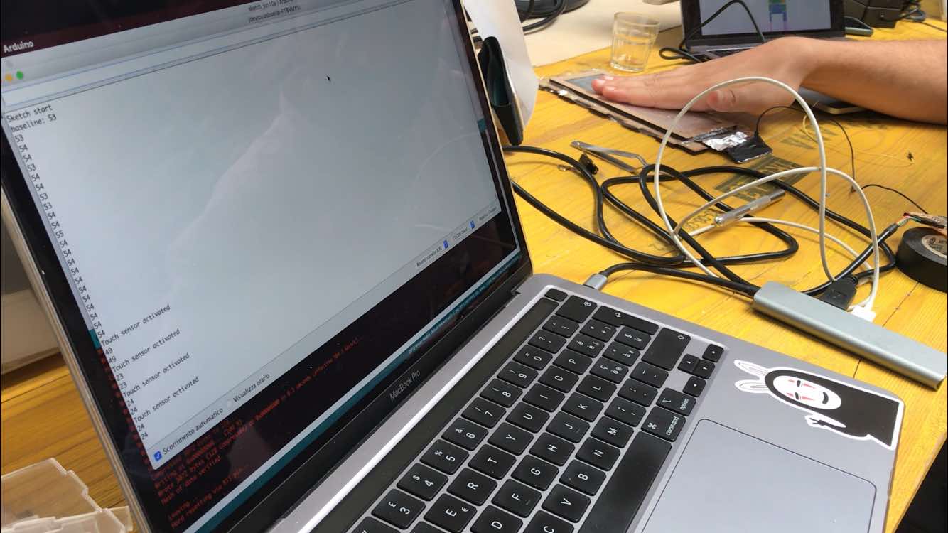
Now if everything works correctly, the moment we touch our foil plane, the sensor will begin to perceive the proximity of our hand, and different values will be written in the serial monitor depending on the proximity!
Next thing is we are going to connect to our board a battery and a simple aluminium sheet (foil will be just fine). The battery is going to be a LiPo (Lithium Polymer) of 3.3V.
Once everything is soldered we put everything in a little lasered box, and the only thing we’re going to see is the aluminium on the top, covered by a thin layer of plastic to protect it.
Here comes the part where we have to make communicate our ESP32 with a cellphone. To make that I used RemoteMe, a free, customizable system which helps you to communicate with your IoT devices. They provide coding wizards to automatically generate webPages and sketch so you don’t have to code everything from scratch. This is the video-tutorial to Send Push notification to android app from ESP.
The site is very easy to use, once logged in we go to the projects section “out of the box” and select the type of app we want to make.
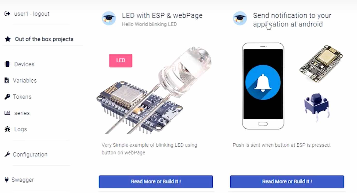
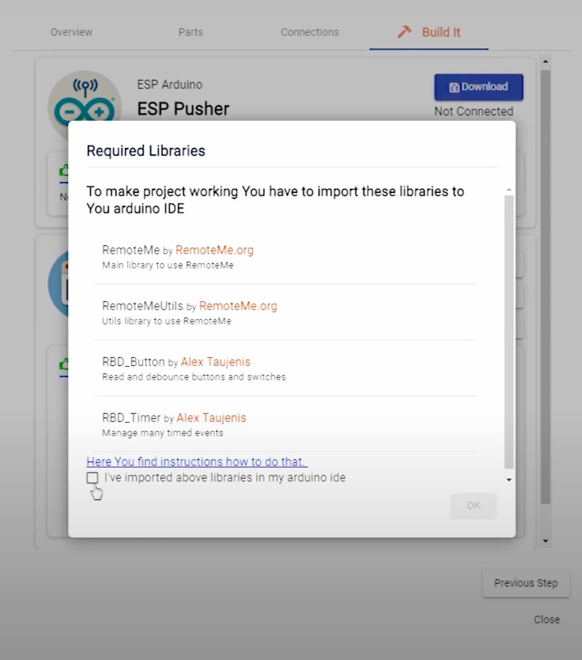
When the button connected to ESP is pressed, a notification will be sent to your android app. You don’t have to install anything on your smartphone, there’s a QR code to scan. You will be asked what type of ESP you are using and the wifi name and password. At this point, a code will be created (remember to download the libraries it suggests) that we can modify at a later time, and a website to control everything via smartphone.
This is the edited code:
#include "WiFi.h"

// RemoteMe
#define DEVICE_ID 1
#define DEVICE_NAME "ESP Pusher"
#define TOKEN "~1258186_Gj88Je4s2nQLDpywHWogz1Wq"
#include <RemoteMe.h>
#include <RemoteMeSocketConnector.h>

// Capacitive touch sensor pin
#define TOUCH_PIN 27

// RGB LED pins
#define LED_R 4
#define LED_G 5
#define LED_B 2

// wifi setup
String wifiSSID = "opendot";
String wifiPass = "opendotlab";

int touchBaseline;
bool touchActive;

RemoteMe& remoteMe = RemoteMe::getInstance(TOKEN, DEVICE_ID);

void setup() {
  Serial.begin(115200);
  Serial.println("Sketch start");

  // LED setup
  pinMode(LED_R, OUTPUT);
  pinMode(LED_G, OUTPUT);
  pinMode(LED_B, OUTPUT);
  turnLED(HIGH, LOW, LOW);

  // Touch sensor average baseline setup
  int accumulator = 0;
  int n = 10;
  for (short i = 0; i < n; i++) {
    accumulator += touchRead(TOUCH_PIN);
  }
  touchBaseline = accumulator / n;
  Serial.print("baseline: ");
  Serial.println(touchBaseline);

  // Connect to wi-fi
  WiFi.mode(WIFI_STA);
  Serial.print('\n');
  Serial.println("Connecting to WiFi...");
  WiFi.begin(&wifiSSID[0], &wifiPass[0]);
  while (WiFi.status() != WL_CONNECTED) {
    delay(1000);
    Serial.println("... nothing yet ...");
  }
  Serial.println("Connected");
  Serial.print("IP address: ");
  Serial.println(WiFi.localIP());

  turnLED(LOW, LOW, HIGH);
  touchActive = false;

  remoteMe.setConnector(new RemoteMeSocketConnector());
  remoteMe.sendRegisterDeviceMessage(DEVICE_NAME);
}

void loop() {
  if (!remoteMe.loop()) { //no connection established
    return;
  }

  if (touchRead(TOUCH_PIN) < touchBaseline) {
    if (!touchActive) {
      String body = "Your attention is requested";
      remoteMe.sendPushNotificationMessage(2, "Call by Willo", body, "badge.png", "icon192.png", "");
      Serial.println("Touch sensor activated");
      turnLED(HIGH, LOW, HIGH);
      touchActive = true;
    }
  } else {
    if (touchActive) {
      turnLED(LOW, LOW, HIGH);
      touchActive = false;
    }
  }
  delay(200);
}

void turnLED(bool r, bool g, bool b) {
  // contrary because of common anode
  digitalWrite(LED_R, !r);
  digitalWrite(LED_G, !g);
  digitalWrite(LED_B, !b);
}
In the initial part define we make communicate our microcontroller with RemoteMe. token is a unique value of our board. In the void.setup part we have the initialization of the LED, where we also choose the initial color (RED). Then the sensor calibration to give a baseline value, as we saw in the previous code. Finally, the connection to WiFi with also a color change of the LED (BLUE). In the void.loop part three main things happen when we touch the surface:
- communication with RemoteMe takes place via a message (Notification)
- LED color change
- enables touchActive (when we touch the surface for a certain time, only one notification will be sent until the hand is removed from it).
Now if we touch the sensor, the “app” will send a notification to the smartphone!
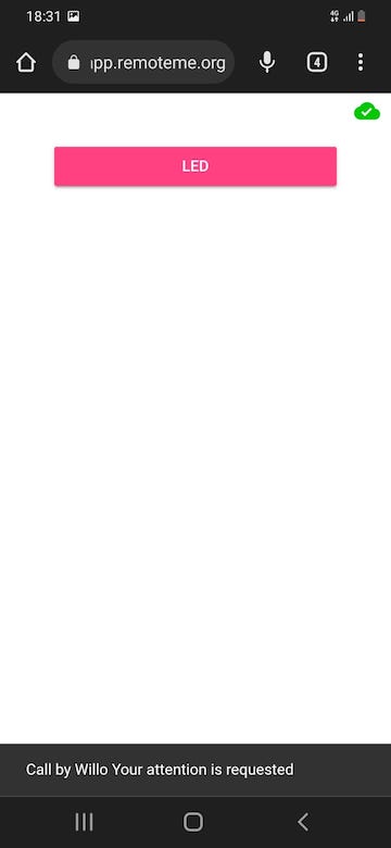
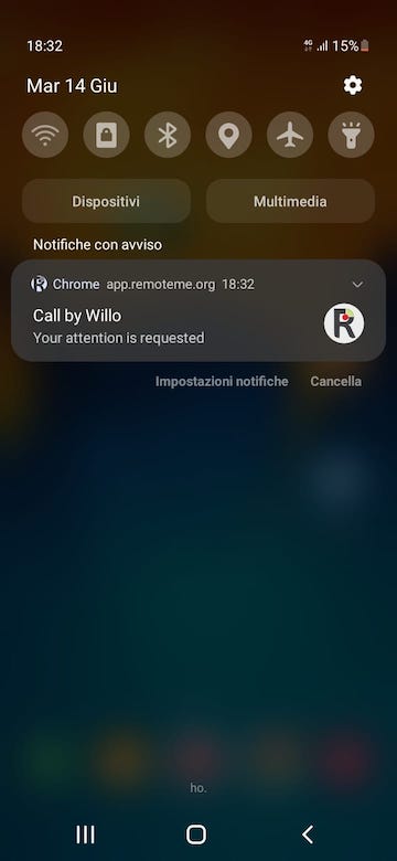
Here it is: