13. Input devices
This week we have to add a sensor to a microcontroller board that we have designed and read it. A sensor is a device, module, machine, or subsystem that detects events or changes in its environment and sends the information to other electronics, frequently a computer processor. Sensors can measure many features, such as light, weight, distance, location, time, sound, vibration, force, air pollution, acceleration, rotation and so on.
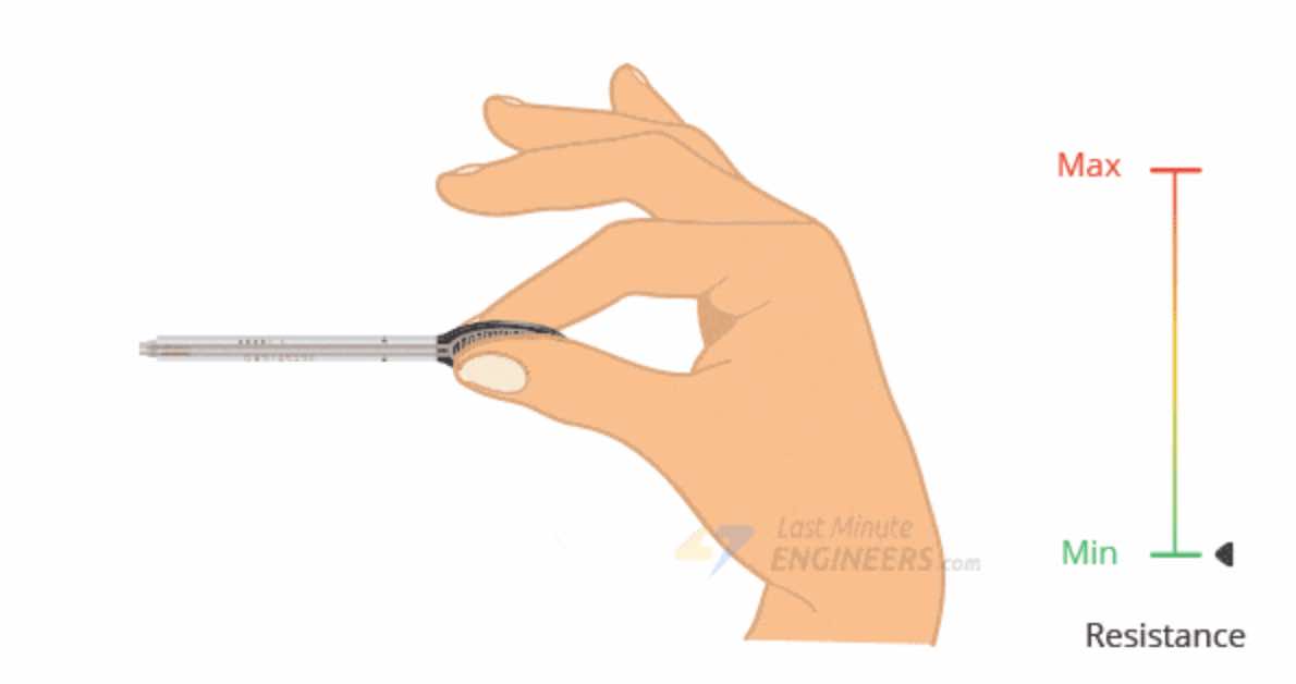
Since I’d like to design a healthcare kit, there’s one specific sensor that can help me measure the patient’s grip, so that we can keep track of the evolution or involution of the strength of a person with motor difficulties. I’m talking about FSRs, that stands for Force Sensitive Resistor. FSRs are sensors that allow you to detect physical pressure, squeezing and weight. They are simple to use and low cost. The FSR is made of 2 layers separated by a spacer. The more one presses, the more of those Active Element dots touch the semiconductor and that makes the resistance go down. FSRs are basically a resistor that changes its resistive value (in ohms Ω) depending on how much it is pressed.
Here’s what happens when you press it:
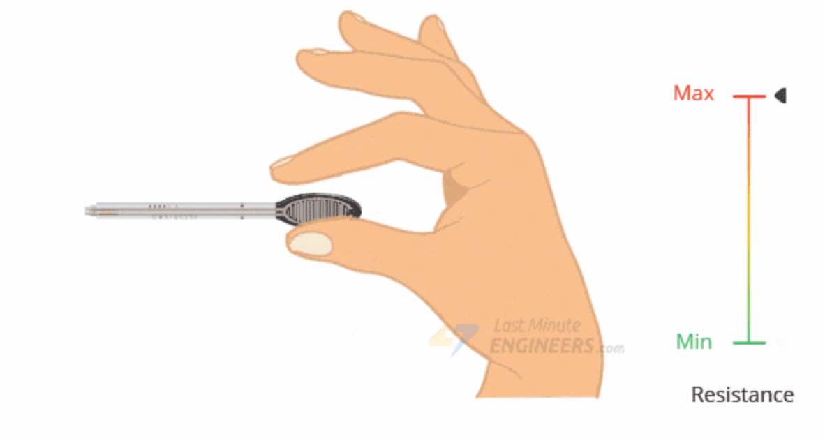
When you do not press:
The easiest way to determine how your FSR works is to connect a multimeter in resistance-measurement mode to the two tabs on your sensor and see how the resistance changes.
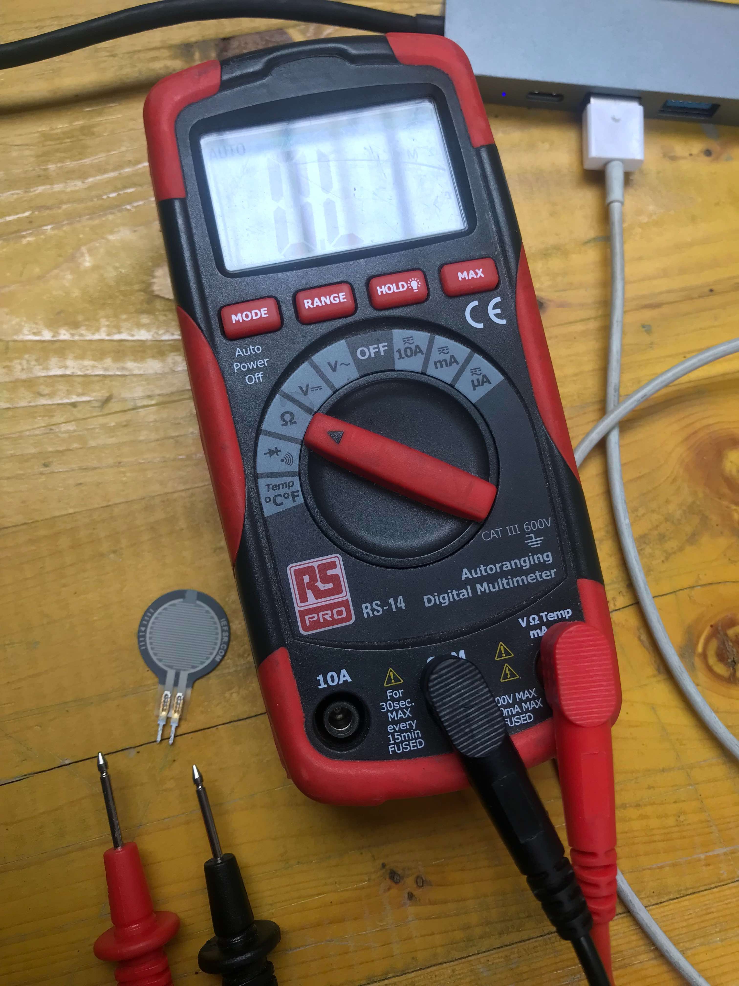
Unfortunately I couldn’t manage to take a photo, but once you connect the multimeter to the two tabs the resistance is infinite, if you press it the resistance will decrease.
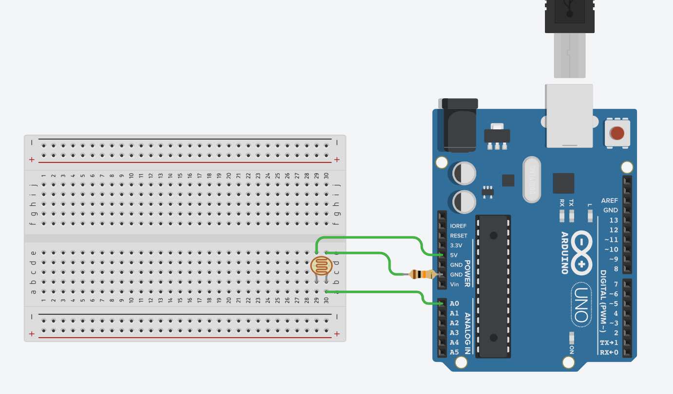
Because FSRs are basically resistors, they are non-polarized (so you connect them either way). The easiest way to measure a resistive sensor is to connect one end to Power and the other to a pull-down resistor to ground. Then the point between the fixed pulldown resistor and the variable FSR resistor is connected to the analog input of a microcontroller such as an Arduino.
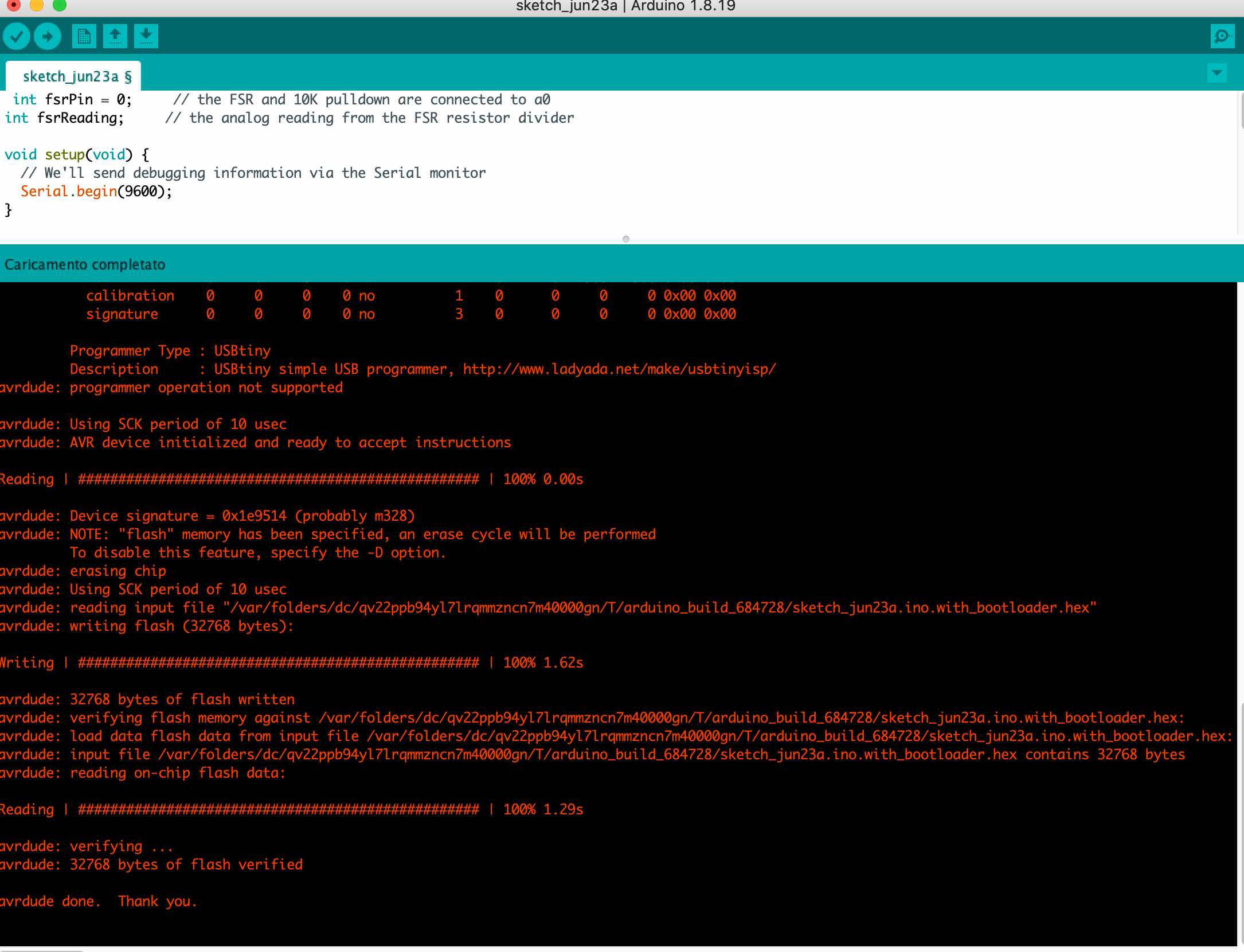
I also tried a code that doesn’t do any calculations, it just prints out what it interprets as the amount of pressure in a qualitative manner.
 int fsrPin = 0;     // the FSR and 10K pulldown are connected to a0
int fsrReading;     // the analog reading from the FSR resistor divider

void setup(void) {
  // We'll send debugging information via the Serial monitor
  Serial.begin(9600);
}

void loop(void) {
  fsrReading = analogRead(fsrPin);

  Serial.print("Analog reading = ");
  Serial.print(fsrReading);     // the raw analog reading

  // We'll have a few threshholds, qualitatively determined
  if (fsrReading < 10) {
    Serial.println(" - No pressure");
  } else if (fsrReading < 200) {
    Serial.println(" - Light touch");
  } else if (fsrReading < 500) {
    Serial.println(" - Light squeeze");
  } else if (fsrReading < 800) {
    Serial.println(" - Medium squeeze");
  } else {
    Serial.println(" - Big squeeze");
  }
  delay(1000);
}
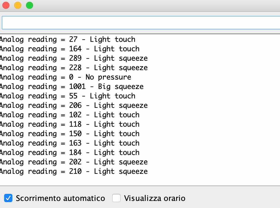
As we can see this are the data printed on the monitor:
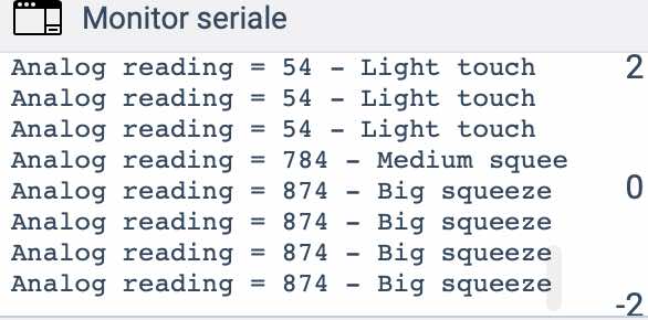
Now let’s make it in REAL LIFE!
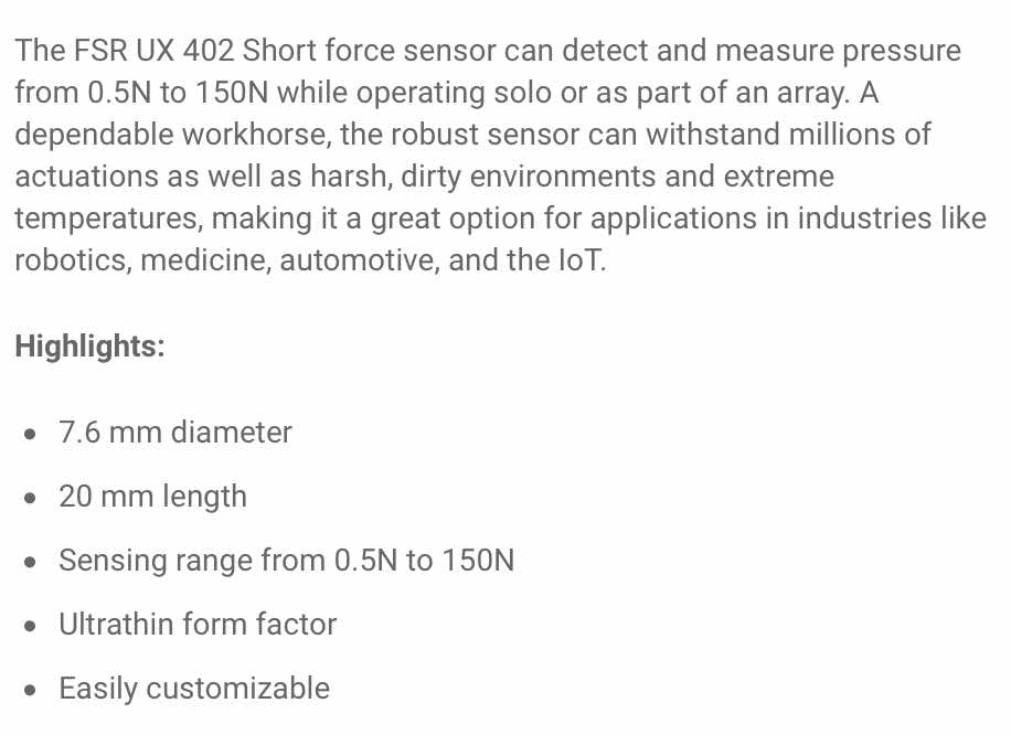
The FSR I’m going to use is a FSR UX 402 Short by Interlink Electronics.
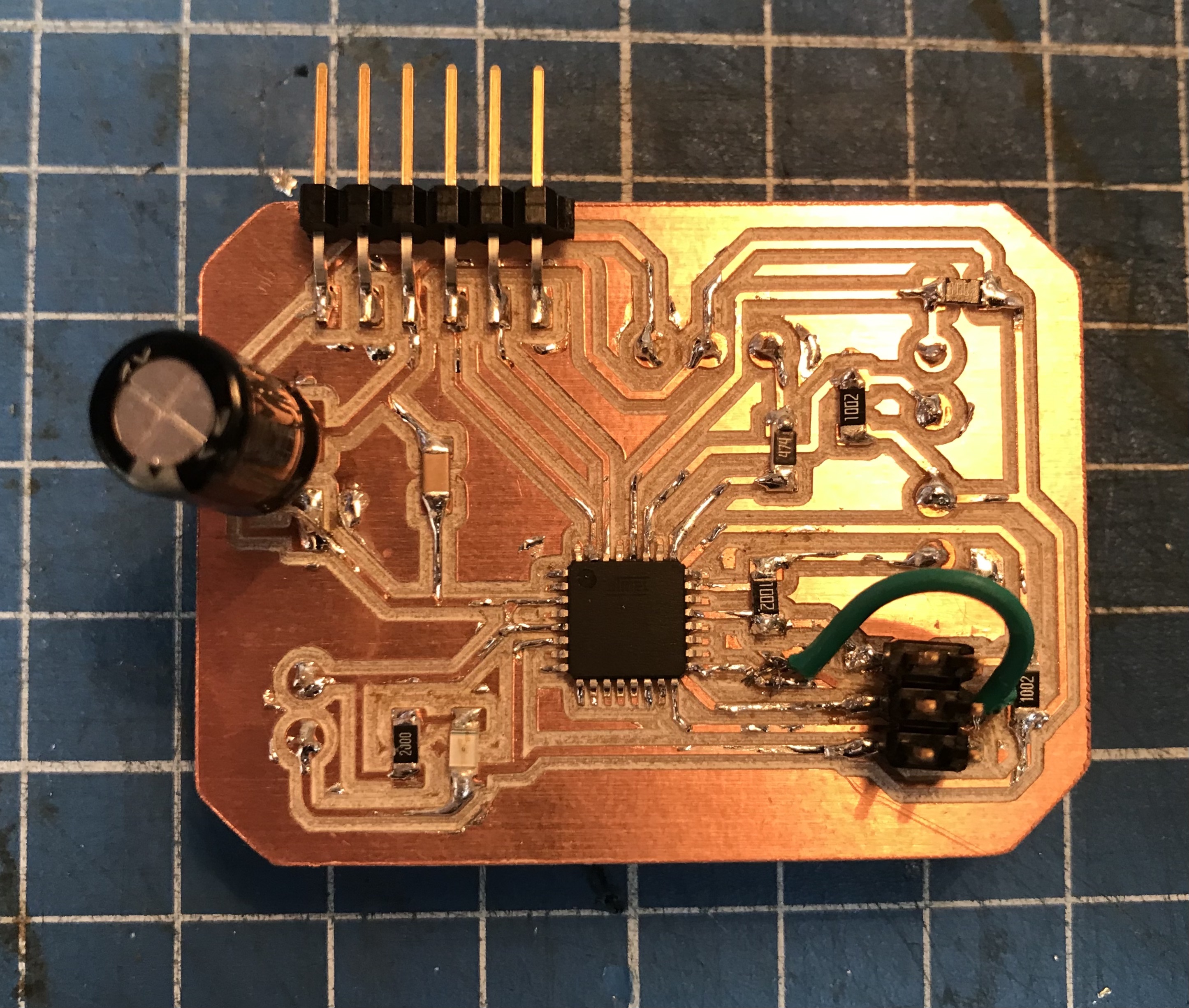
I attached it to my megaboard as you can see below, using a connector, two jumpers and some tape:
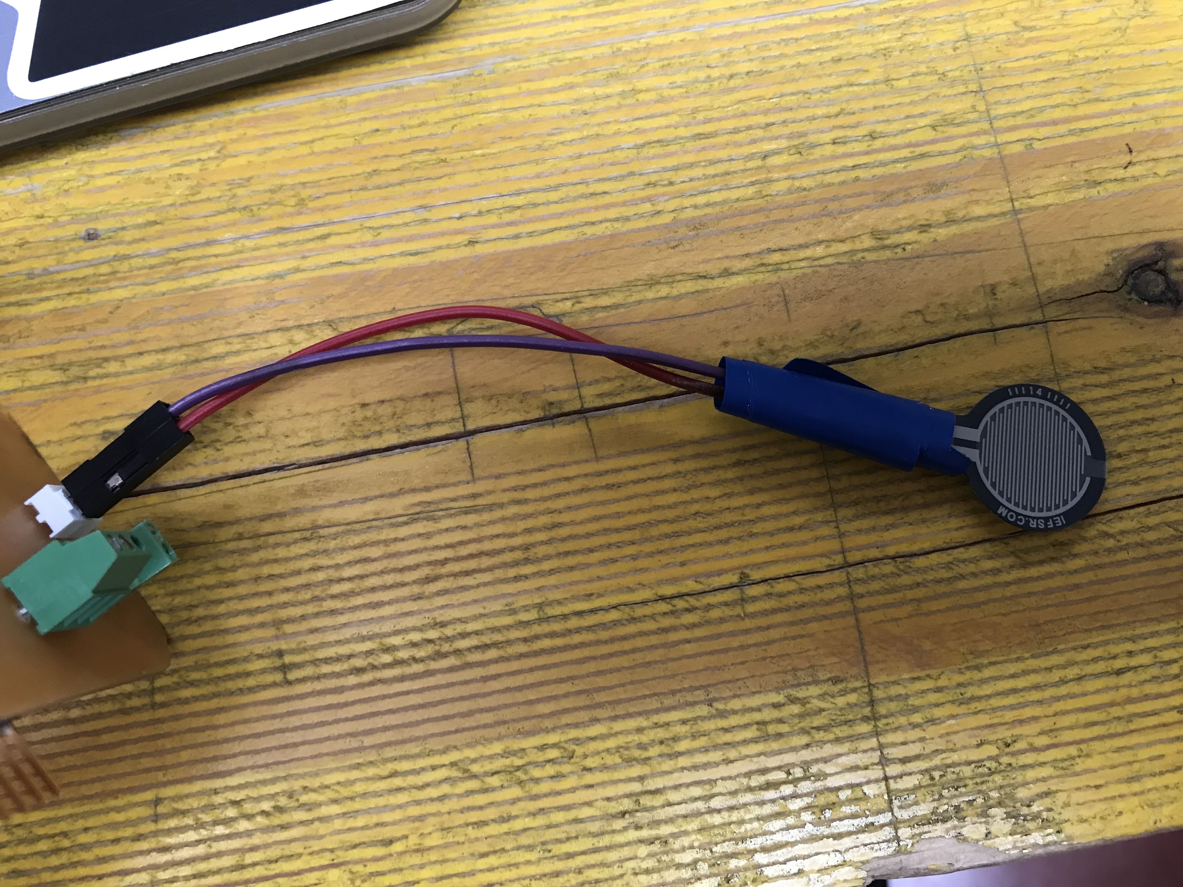
Programmed earlier with ArduinoIDE:
And this is the result! Every time I pressed the FSR, a different value was printed in the serial monitor.
You are welcome