4. Computer Controlled Cutting
Task: Computer-Controlled Cutting
- Group assignment:(Page Link is Here)
- characterize your lasercutter’s focus, power, speed, rate, kerf, and joint clearance
- Document your work to the group work page and reflect on your individual page what you learned
- Individual assignments
- Design, lasercut, and document a parametric press-fit construction kit, which can be assembled in multiple ways. Account for the lasercutter kerf.
- cut something on the vinylcutter
This is the start of our machine week. I was waiting for these days.
After the class of prof. Neil, we are just a little busy.
Tasks in this week
- Vinyl cutting
- Laser cutting
- Laser engraving
Vinyl cutting
In sticker shops, I’ve seen vinyl cutters. But, I was unable to touch or use it.
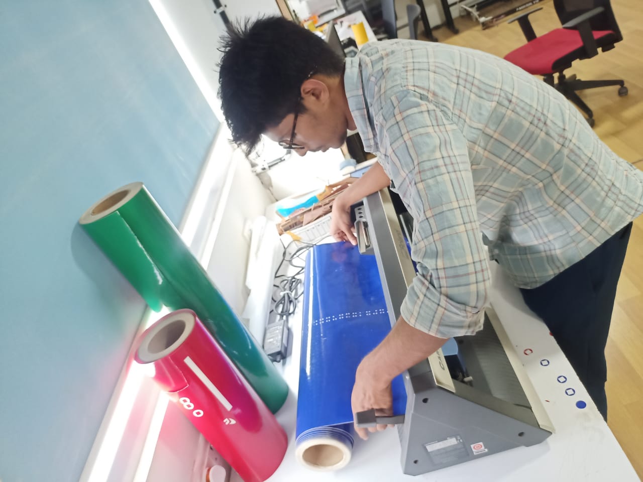
Roland GS-24
This is the vinyl cutter in our fab lab.
It runs with a simple mechanism similar to that of a printer.
In the vinyl cutter, a knife moves left to right, while the vinyl sheet moves in back and forth. As the first step, I read User Manuel of Roland GS-24 (link here)
Important parts in the Roland GS-24.
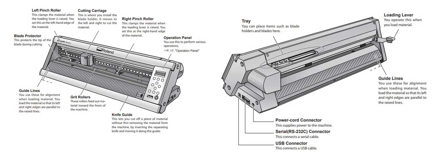
Cutting Carriage: It moves to the left and right and the blade attached to it cuts the vinyl sheet.
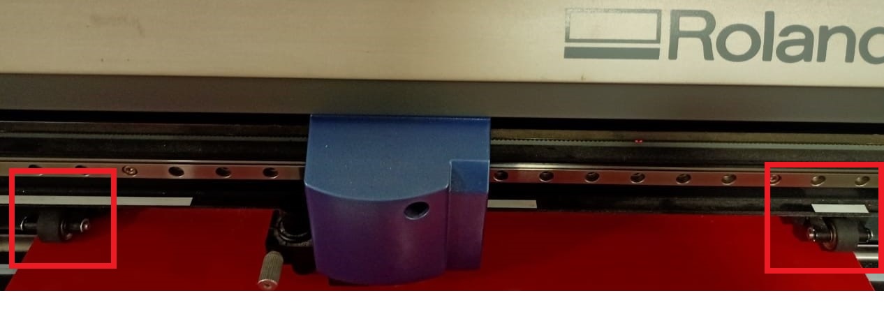
Pinch Rollers: There are 2 pinch rollers and we have to set these at the 2 edges of the vinyl sheet according to the width of the vinyl sheet.
Loading Lever: We should first raise the lever before loading the vinyl sheet.
Operation Panel: This panel includes a display and some buttons.
By selecting different options we can perform various operation
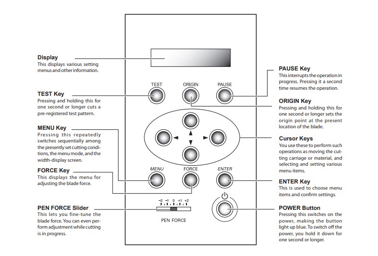
Test Key: We can check the settings are correct or not by pressing the test key then the machine cuts a test pattern.
After testing and evaluating the cutting, we can change options if want.
Origin Key: To select a point on the sheet as the origin point, after setting the position of the blade, click and hold the origin key for one second.
Steps of vinyl cutting
Create a design for cutting.
To create a design for vinyl cutting, a vector designing software is recommended.
I used Inkscape.
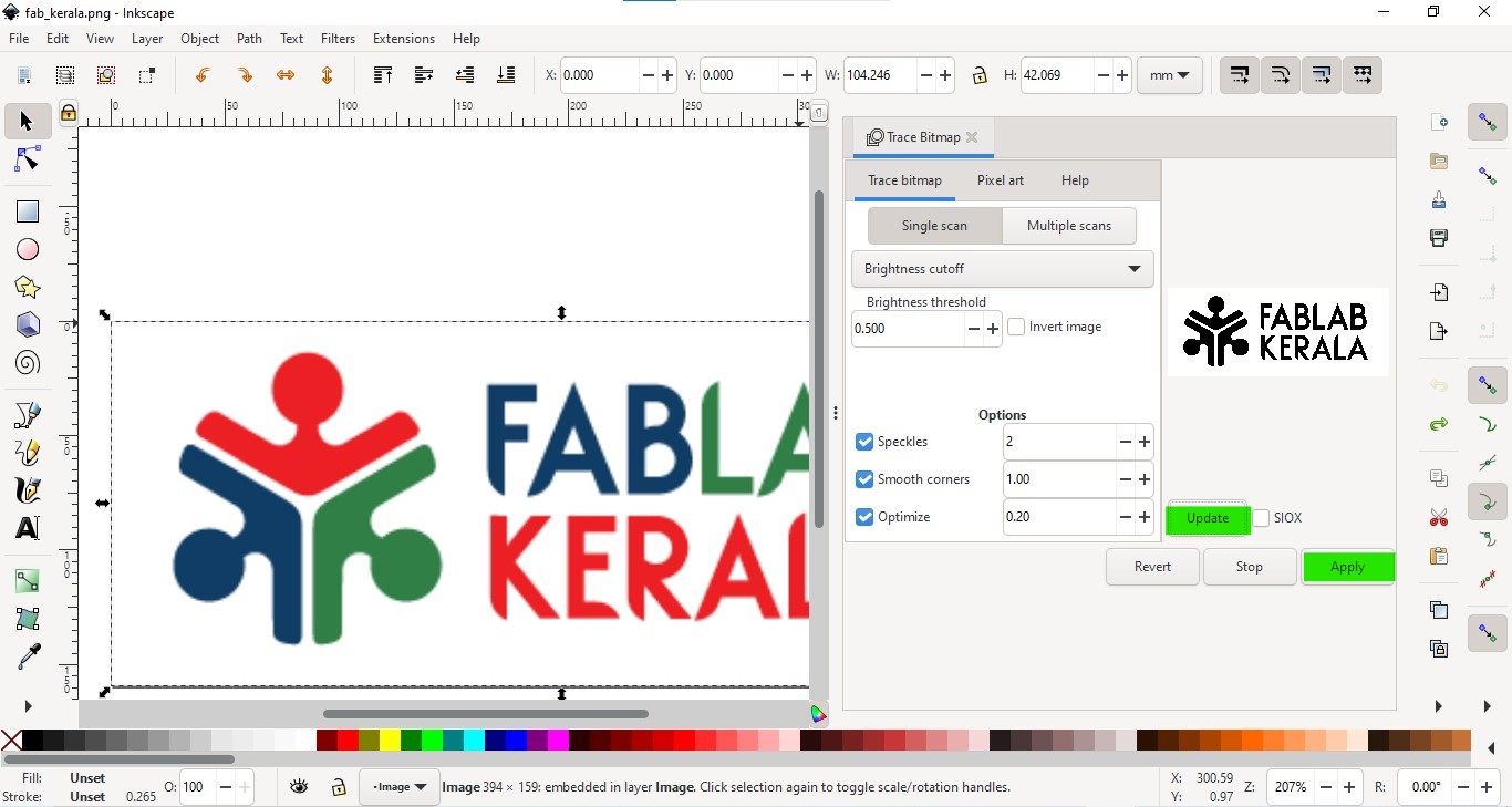
Convert into vector graphics.
After importing a raster image (.png, .jpg),
- Select the image
- Go to path → trace bitmap
-
In the opening dialogue box, adjust different options.
To get the preview, click on the update button.
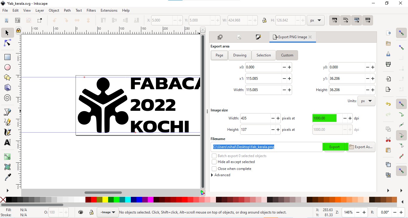
-
After editing, go to File→ Export to .png
-
Set the dpi more to get a more clear image, Then click on Export.
Transfer the file to the computer which is connected to the vinyl cutter.
To transfer the png file into the vinyl cutter-connected computer, our mentor told us about a different fie sharing website **sendanywhere.com.** I felt it is a very best file-sharing method.
Setting up the machine
- Load the vinyl sheet into the machine after lowering the loading lever.
- Position pinch rollers in the correct position by moving each roller left and right.
- Power on the machine.
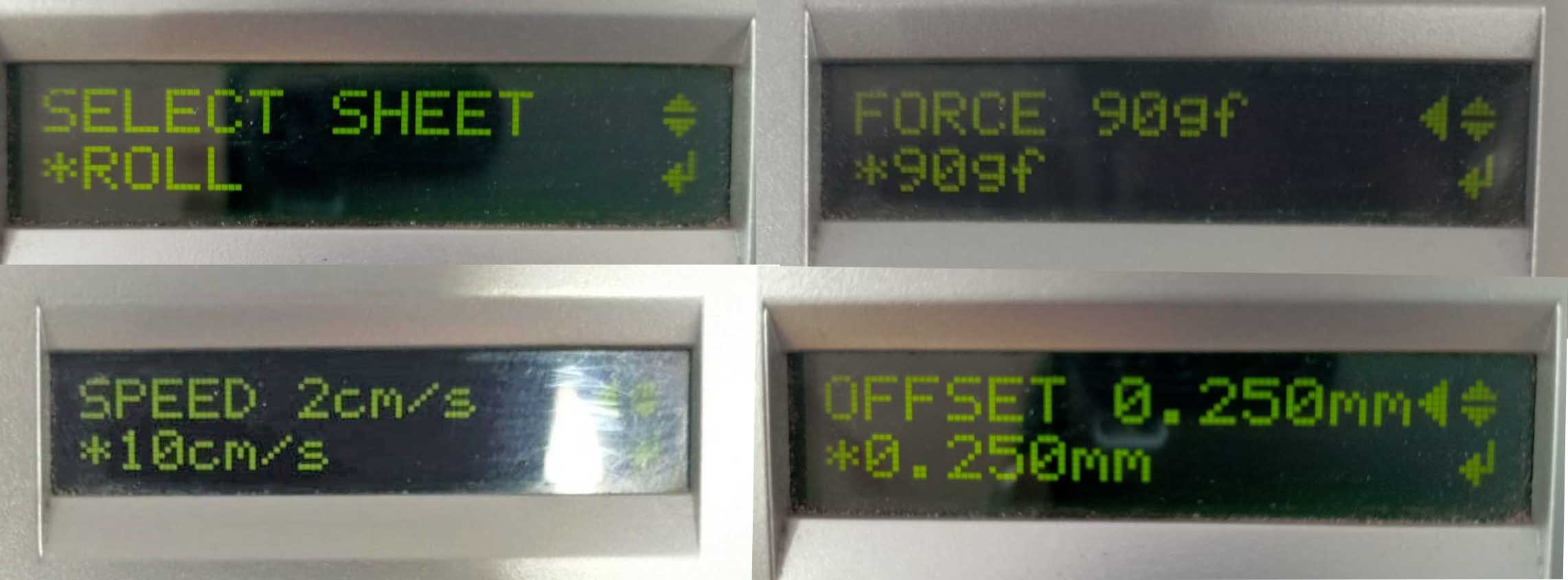
- Go to the ‘SELECT SHEET’ option and select ‘ROLL’
- In the menu, go to ‘CUTTING FORCE’ and select ‘50 gf’.
- Go to ‘CUTTING SPEED’ and select ‘20 cm/s’.
-
Go to ‘BLADE OFFSET’ and select ‘0.254’.
Cutting test
After the above steps,
Position the cutting carriage in a location.
Press and hold the’ TEST‘ button for a few seconds,
Then check the cutting piece by peeling off the cutting portion,
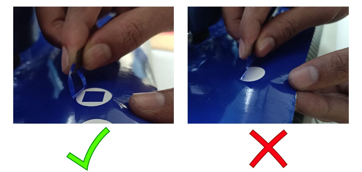
If the cutting isn’t quite right, we can repeat the cutting test by adjusting the blade extension length and other menu options (cutting speed, cutting force, etc.)
Setting origin point.
We can set a position in the sheet as origin by clicking the ‘ORIGIN’ key after positioning the cutting carriage.
After setting up the vinyl cutter, we can convert our design file into machine language.
Setting up Mods
After receiving the designing file in the computer which connected to vinyl cutter, we used mods to send our design file into the Roland GS-24 vinyl cutter.
What is Mods?
mods community edition is a fork of CBA mods research project. mods is a modular cross platform tool for fablabs. It is based on independent but interrelated modules. mods could potentially be used for CAD, CAM, machine control, automation, building UI, read input devices, react to to physical models, and much more. The possibilies are endless. Ref: fabcloud.org/pub/project/mods
Steps I followed are given below.
-
Open the mods folder and open the terminal in that directory
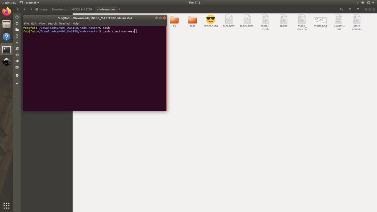
-
Type ‘bash mods-servers’ and press enter.
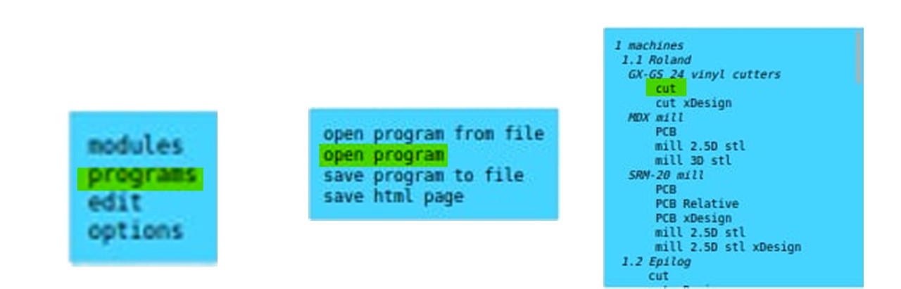
bash mods-servers - In the opening window, click the right button of the mouse and select programs.
- Select open program
-
Select Machine→ Roland→GX-GS 24 vinyl cutters → cut
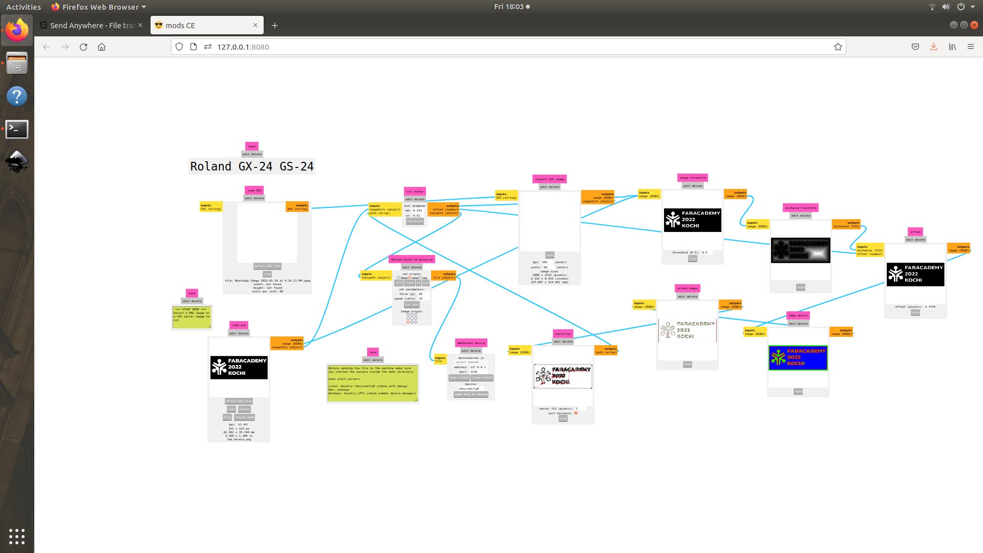
-
I imported my file by clicking on the ‘read .png’ button.
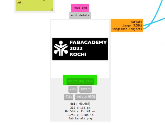
-
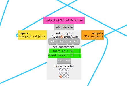
In the ‘Roland GX/GS-24 Relative’ option, I selected speed 10 cm/s and force 50 g.
-
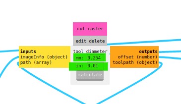
In the ‘Cut raster’ option, I selected tool diameter as 0.254 mm and clicked on Calculate button.
-
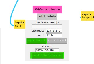
In the ‘Websocket device’ option, I clicked on ‘open socket’ and click on the ‘Send file to device’ option.
Pasting of vinyl sticker
After cutting the sticker portion from the roll.
-
Paste a transfer sheet on the vinyl cut portion
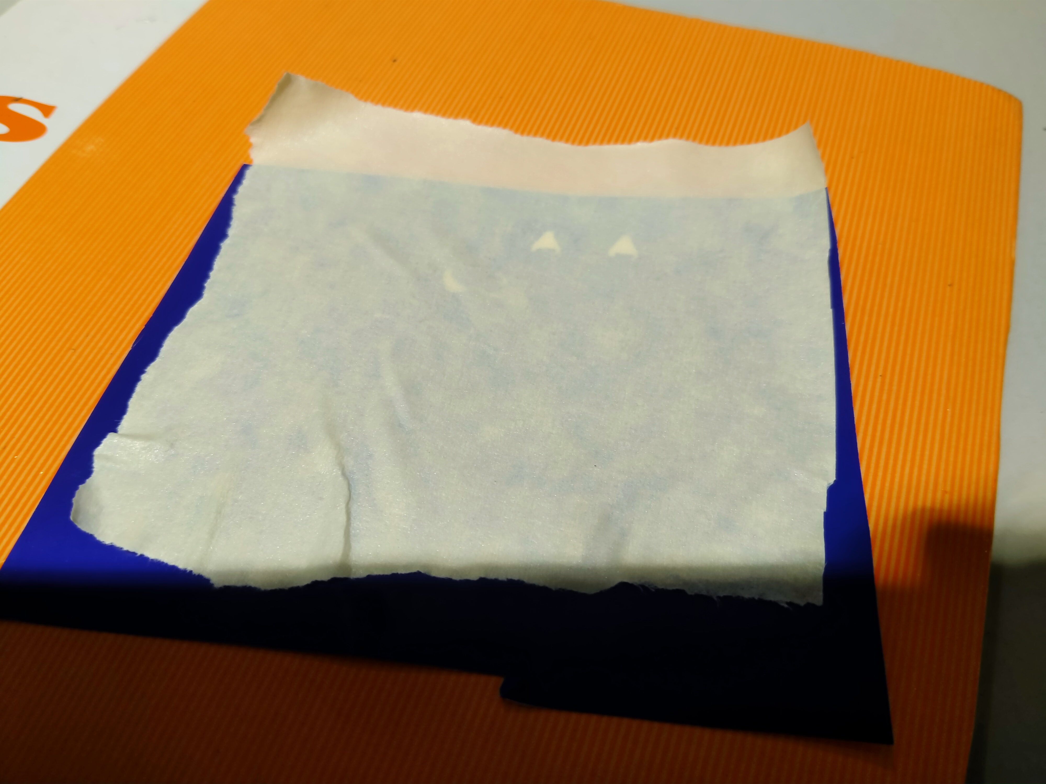
-
Remove unwanted portions from sticker and paste it on a surface.
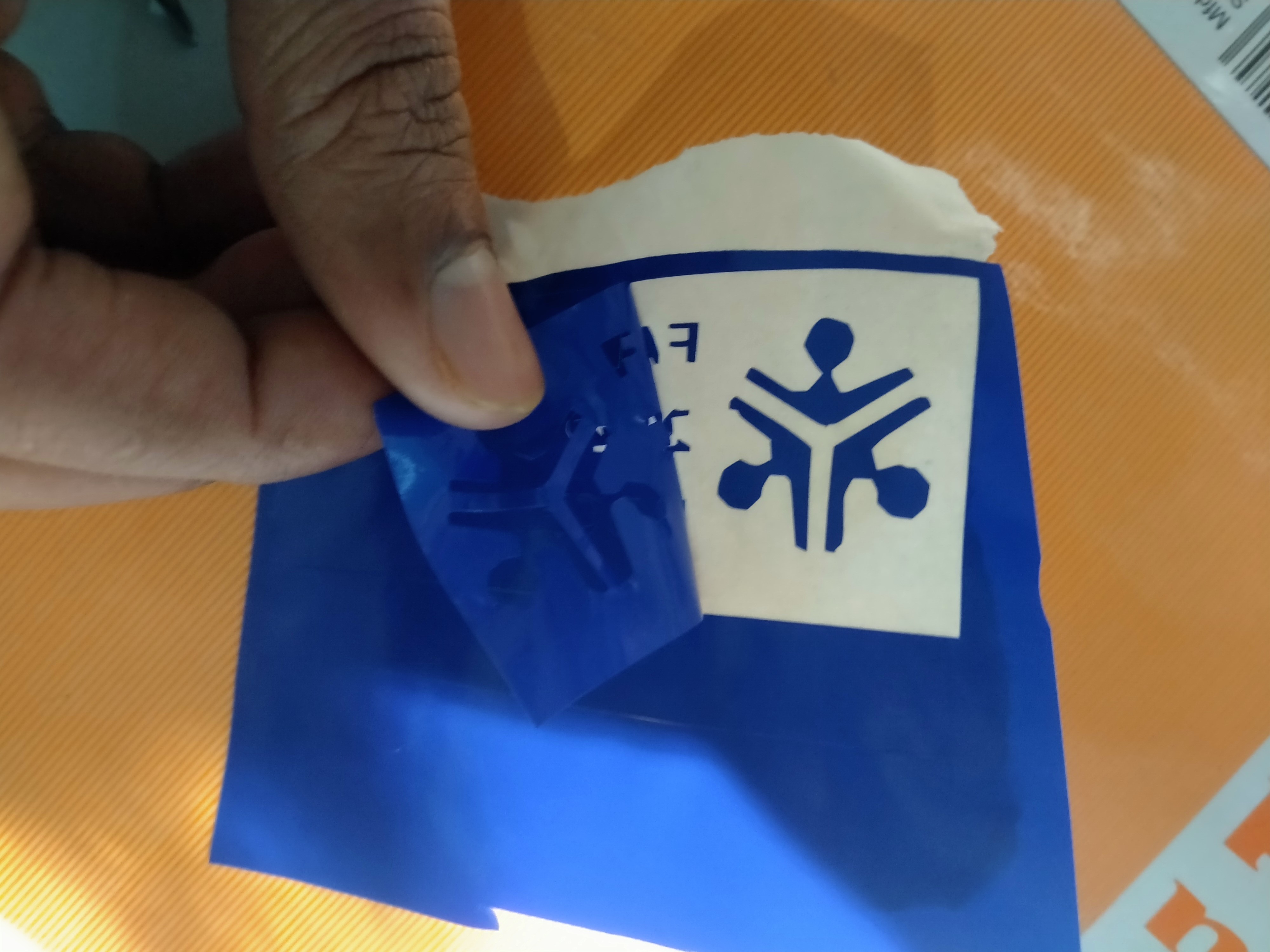
-
Paste it on a surface and remove the transfer sheet carefully.
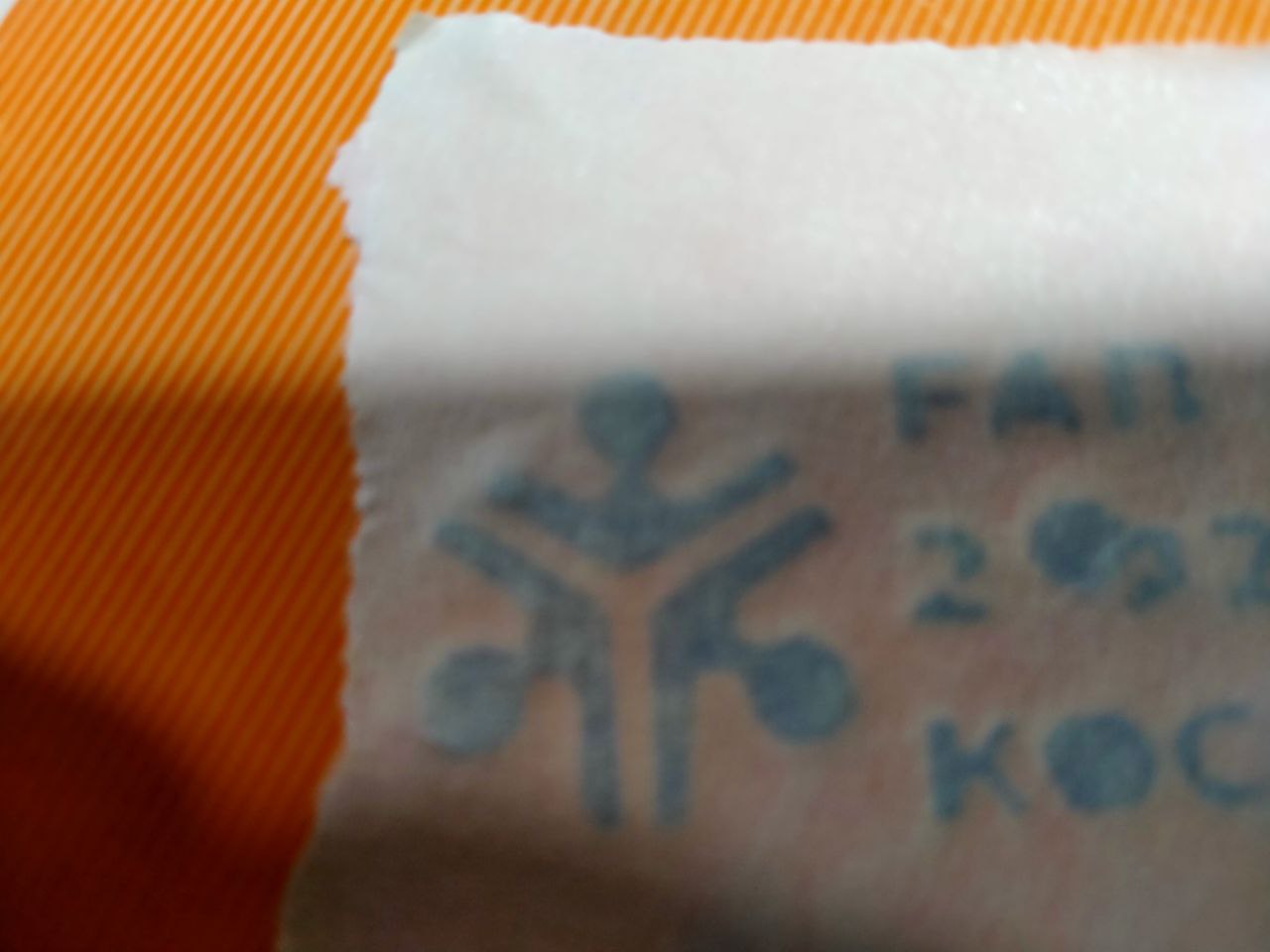

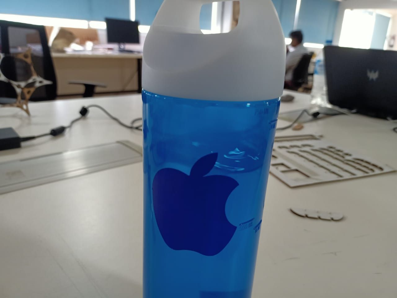
I couldn’t paste the sticker in clearly, because the size of the image was small.
So I made some more stickers and stick them in my notebook and on water bottle.

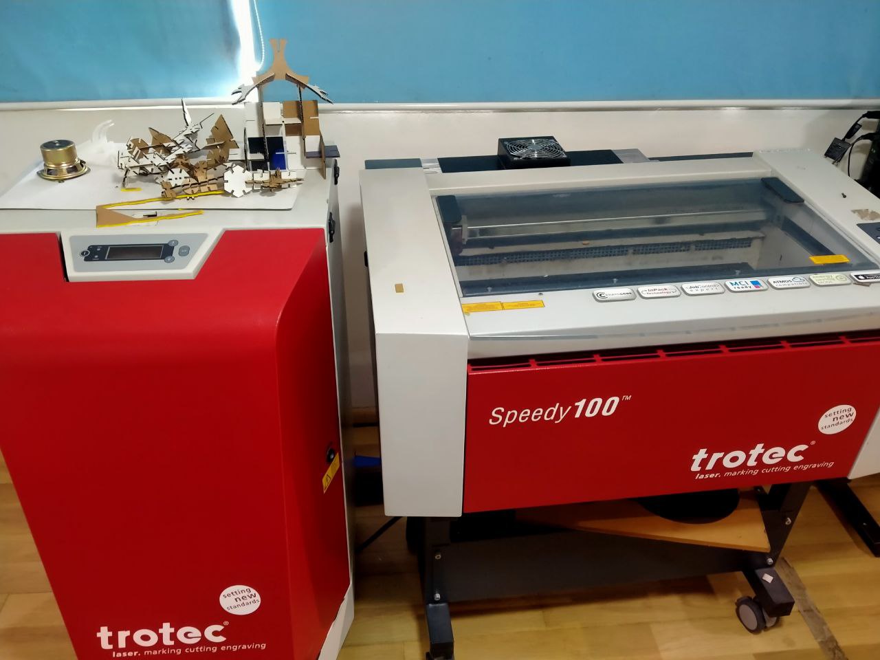
Laser cutting
Our laser engraving machine is Trotec speedy100. It is a 30watt CO2 laser cutter
Different parts of the laser cutter.
Laser resonator: The laser beams are produced inside the laser resonator and it reaches to the cutting head through many reflections on different mirrors.
Cutting head: The cutting head includes a convex lens. which narrows the laser beam for cutting.
The cutting head can move in the XY plane with the help of 2 axes.
Work bed: Material for cutting is placed on the work bed. We can focus the laser beam by moving the work bed up and down.
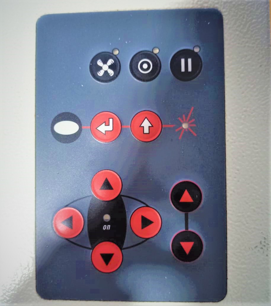
Control panel: Which includes a display and some buttons.
We can position the cutting head and work bed using the navigation keys.
Setting up of laser cutter.
Power on.
Place the material to cut on the bed.
By clicking navigation keys, position the cutting head.
Focusing procedure
To focus the laser with a narrow beam,
-
place the key in the gap.
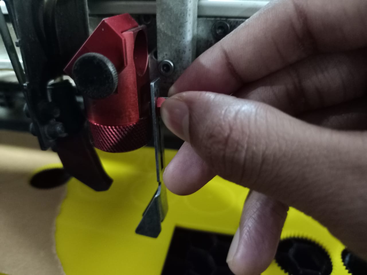
-
Then rise the cutting bed very slowly using the navigation keys.
-
We must stop rising the cutting bed at the time of falling of the key.
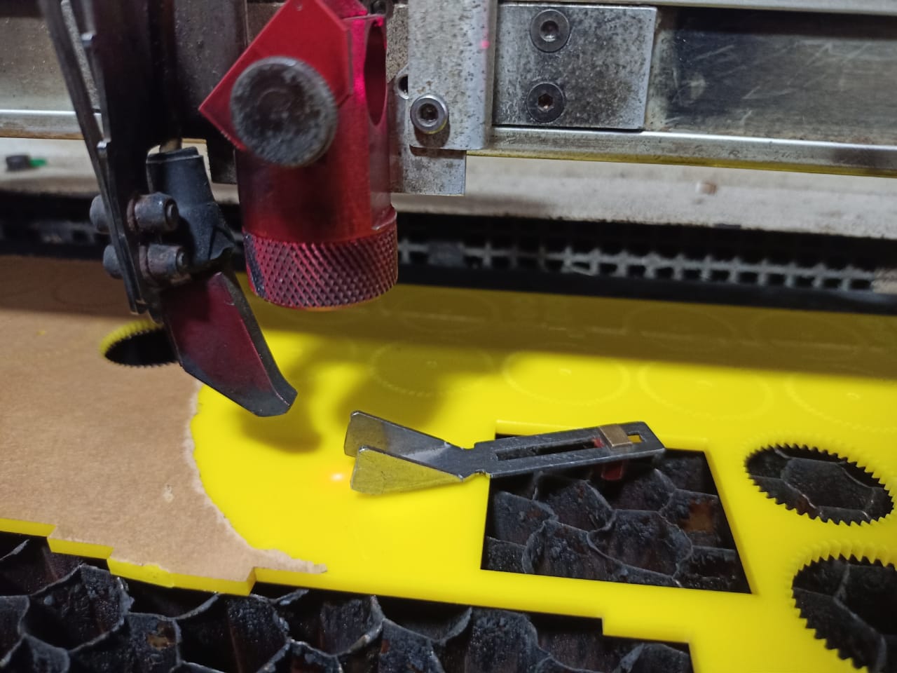
laser beam is focused now.
Create parametric construction kit
I think the parametric construction kit exercise is the best way to understand parametric design, use of the jig, and laser cutting.
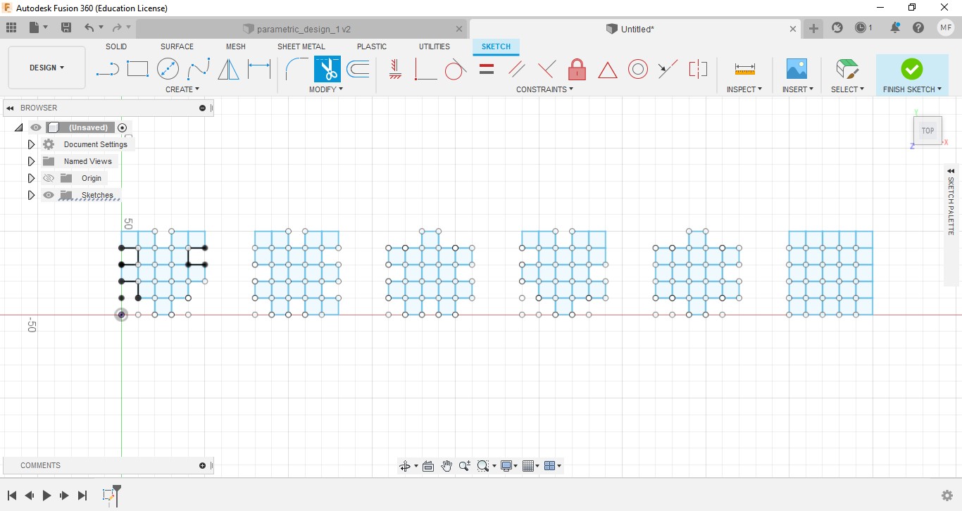
Parametric design
After searching about models of the parametric construction kit, I made an idea about the design.
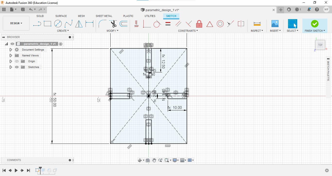
Then I started drawing in Fusion 360.
Instead of normal drawing, here I set some parametric values(Thickness, noch length, noch breadth, etc.)
For this, select ‘Modify’→ ‘Change Parameters’
We can add new parameters by clicking on the ‘+’ icon near ‘User parameters’.
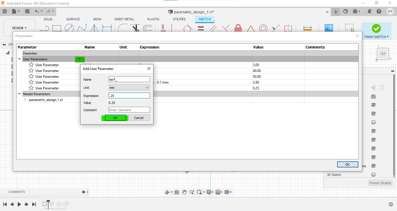
At the time of drawing, we can use these parameters as dimensions.
After the extruding the sketch, offset all side edges by the length of the kerf.
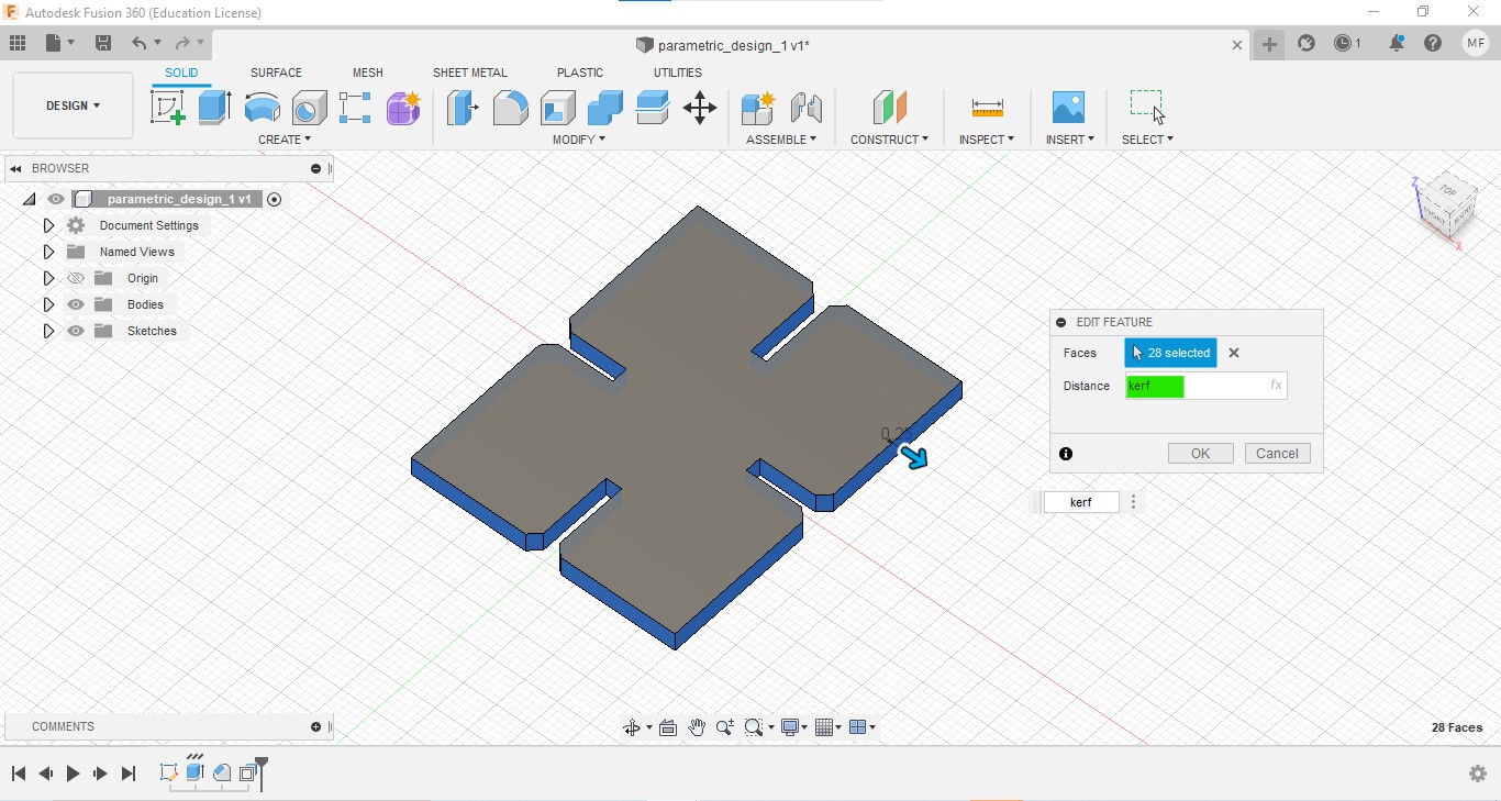
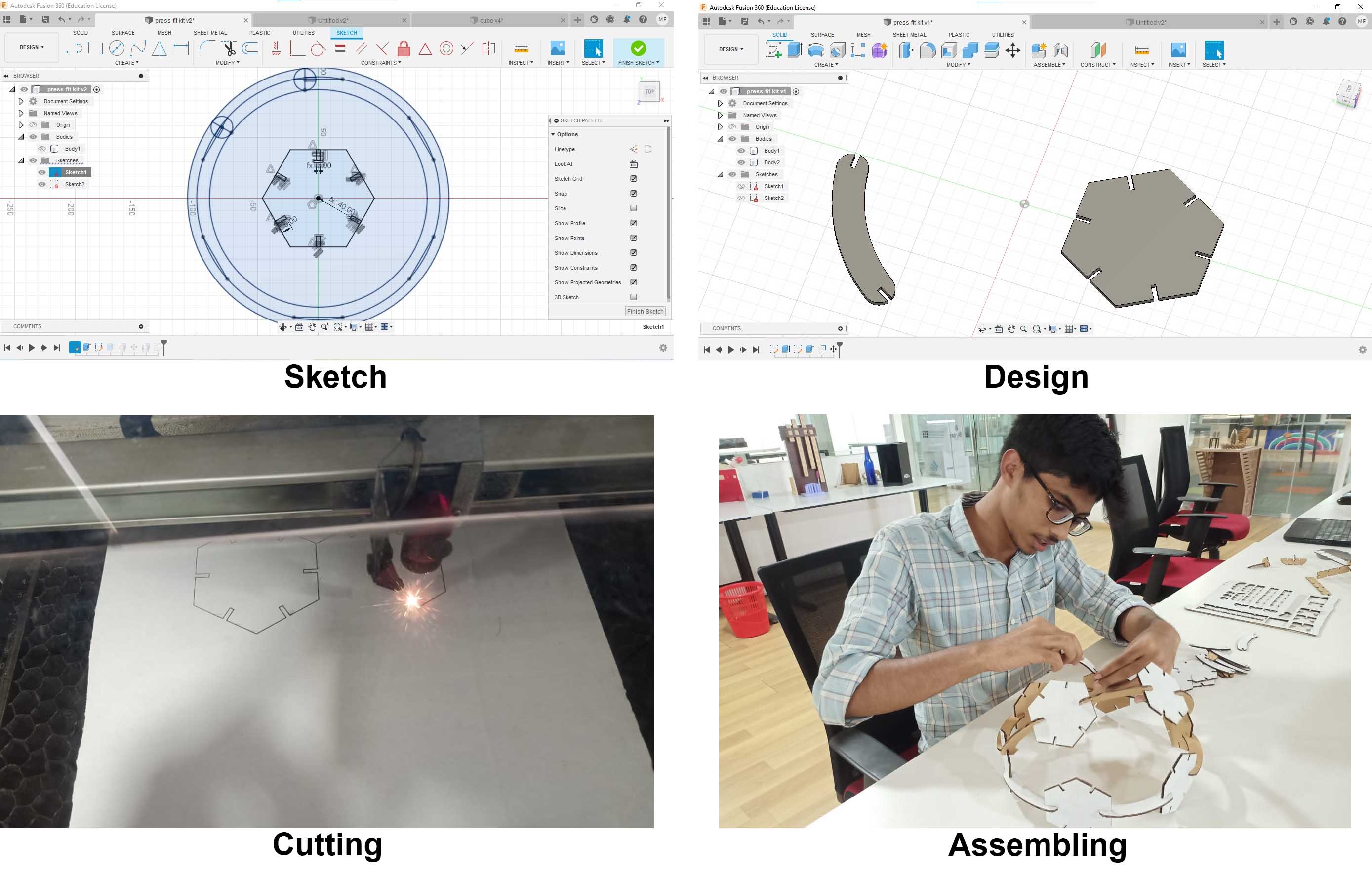
Then create a sketch on the top face, and project the design.
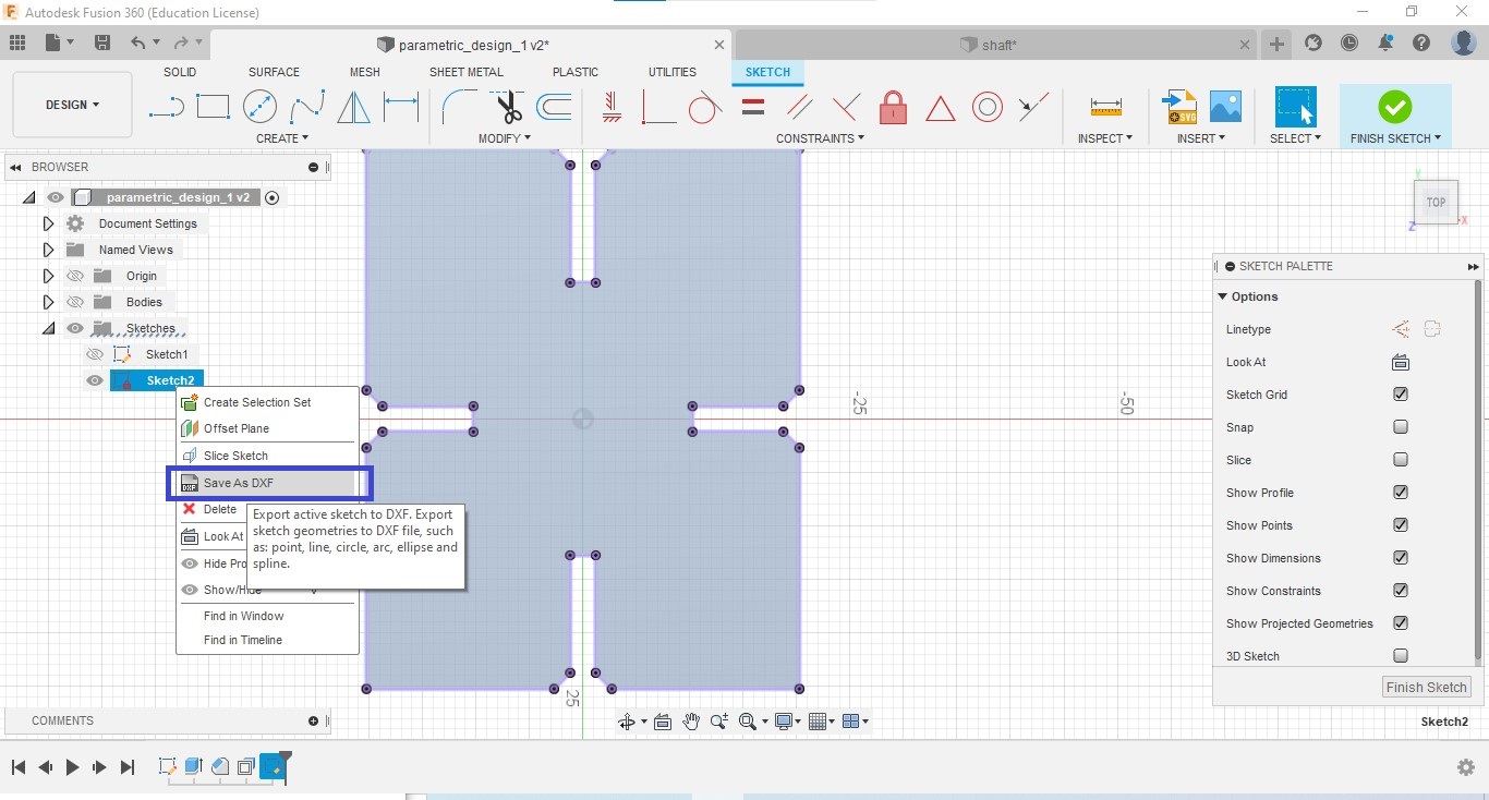
Then select the sketch in Browser → right click and click on Save as DXF and save the file.
Edit the .dxf file for Laser cutting
We have to adjust stroke thickness and color for our laser cutter. I used Inkscape for that. we can use any other software which supports that file.
The steps are given below.
- Import the .dxf file in Inkscape.
- Select the design and go to Object→ Fill and Stroke
-
Go to Stroke paint→ Set stroke paint as red Go to Stroke style → Set width as 0.1 mm
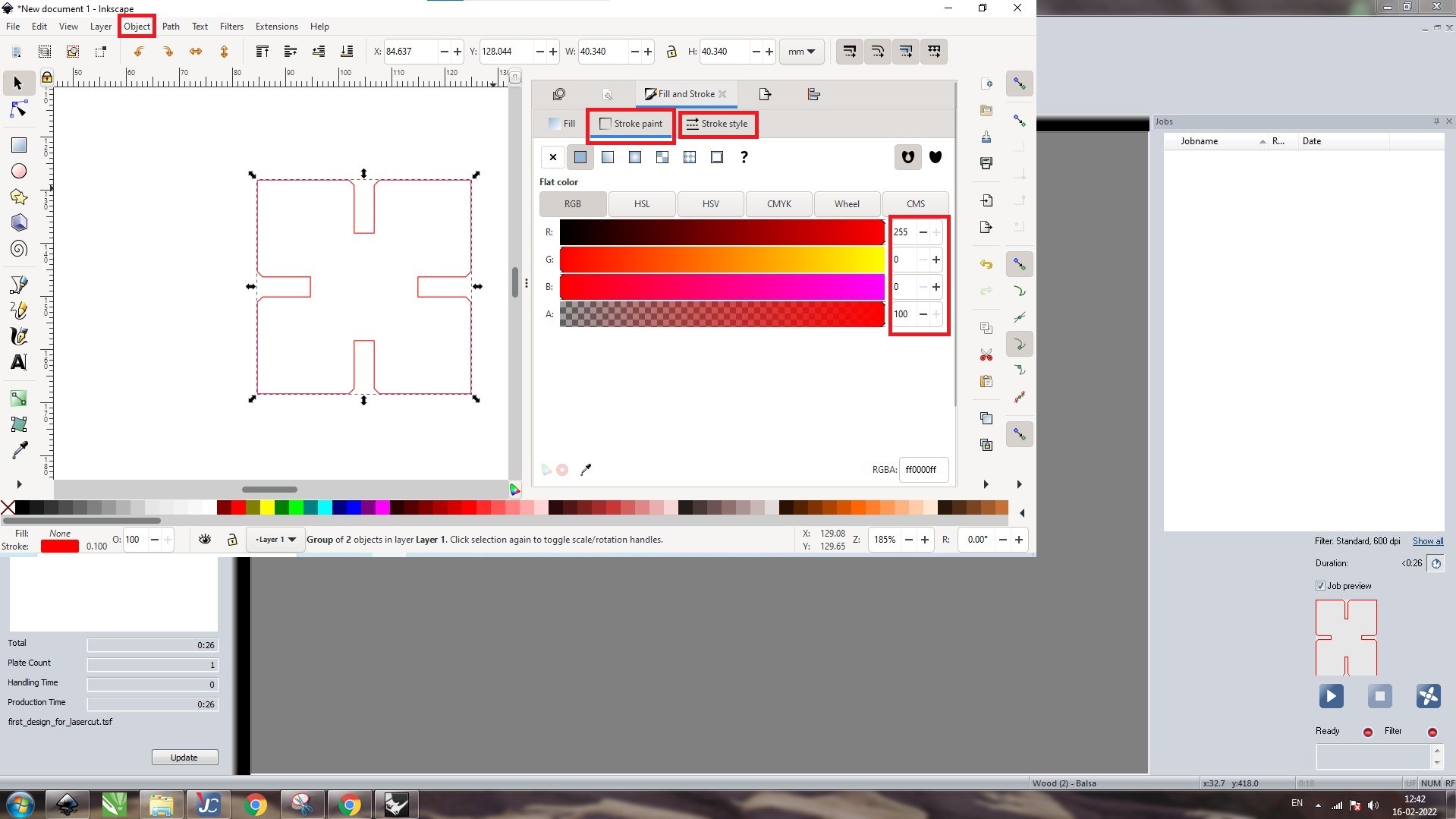
Now the design became ready for Laser cut.
Using Job control¶¶
Import .dxf file of the design in Inkscape. we can use any other software which supports that file.
set the stroke width at 0.1 mm, and change color into red.
Then go to print and make sure the trotec laser cutter is selected.
The window of Job control website will open now.
Drag and drop the file we want from the right portion to the work bed and position it.
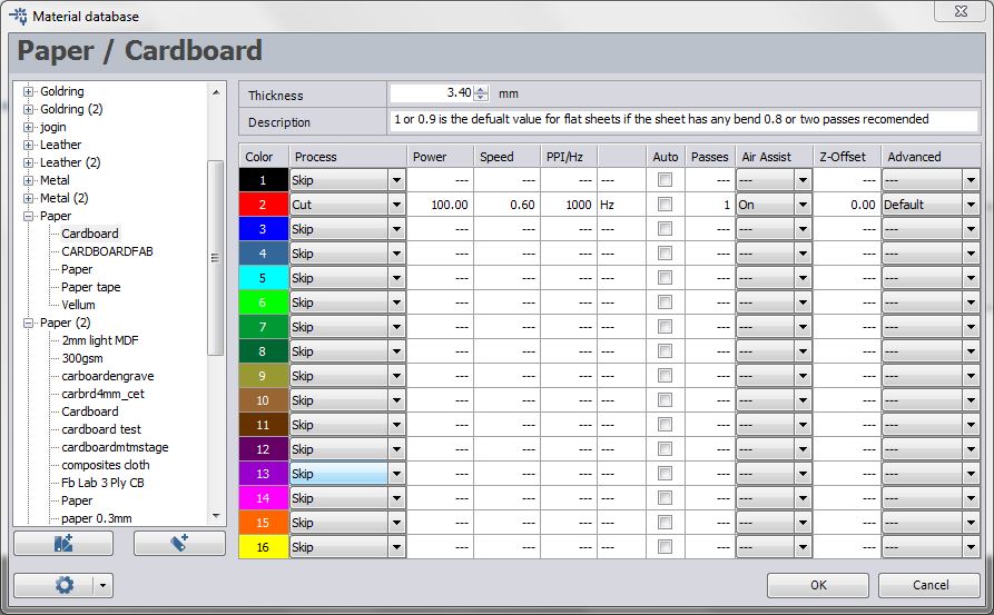
Then click on the material database option, select the material, and make sure the speed and power are appropriate.
Then click on the start button. Then the cutting process will start.
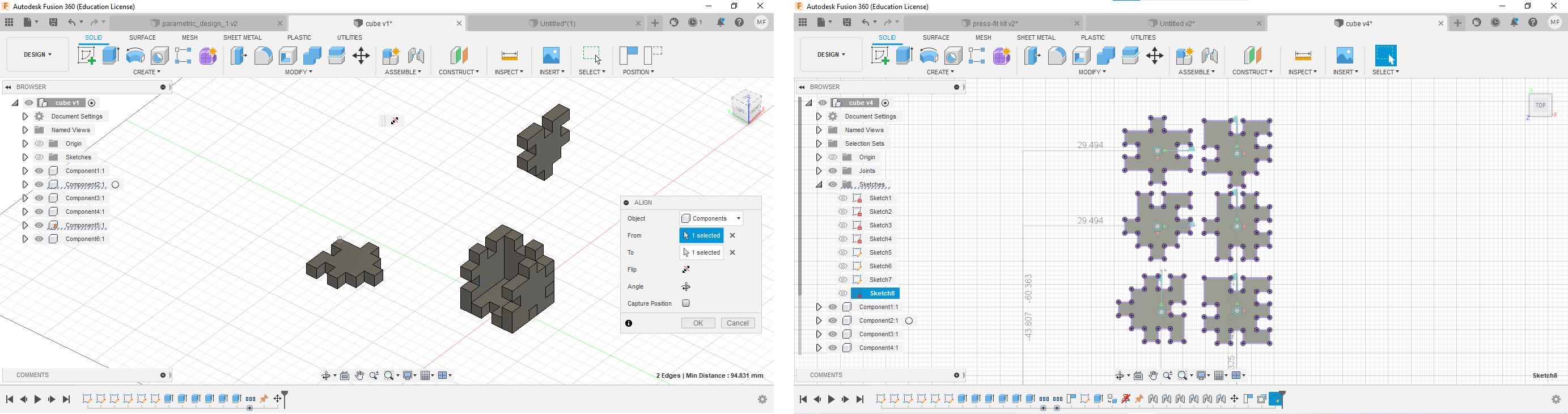
After some basic model, I made a cube puzzle,
It was a little difficult for me. But, after create 6 faces of the cube puzzle, I have got a clear idea about constrains and parametric design. Our Instructor Rahul helped me to got a clear idea about constrains.
After creating 6 faces, I assembled those. and create a projection of all faces and that sketch saved as a .svg file.
After sending the file to the computer connected to the laser cutter,
- Open that file in Inkscape, set the stroke width at 0.1 mm, and change strock color into red. Then go to print.
- In the Job control, Set the speed, power, and passes in the material database.
I had to repeat the cutting twice because the noches were tight at the first cutting. Then I increased the thickness a little, then I got the correct fit puzzle.
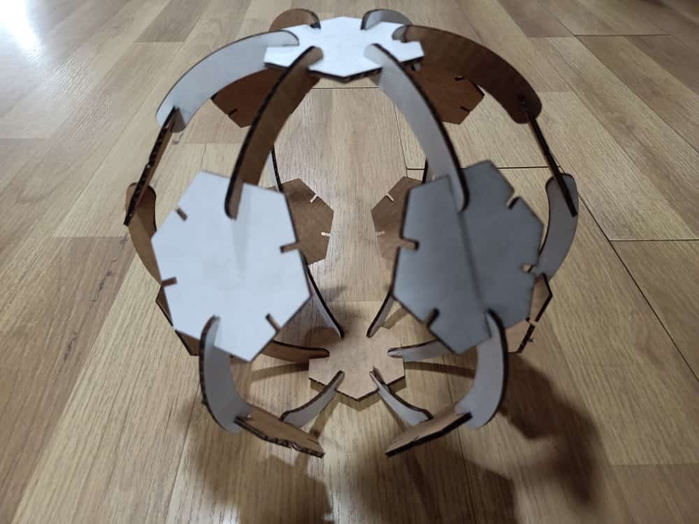
Press fit kit
I created a press fit ball by using hexagons and connectors.
Group assignment
Kerf¶¶
During any cutting process, the cutting tool causes some excess material to be lost in addition to the specified design. When a laser cuts a material, its path burns off some material, known as the kerf of a laser cutter.
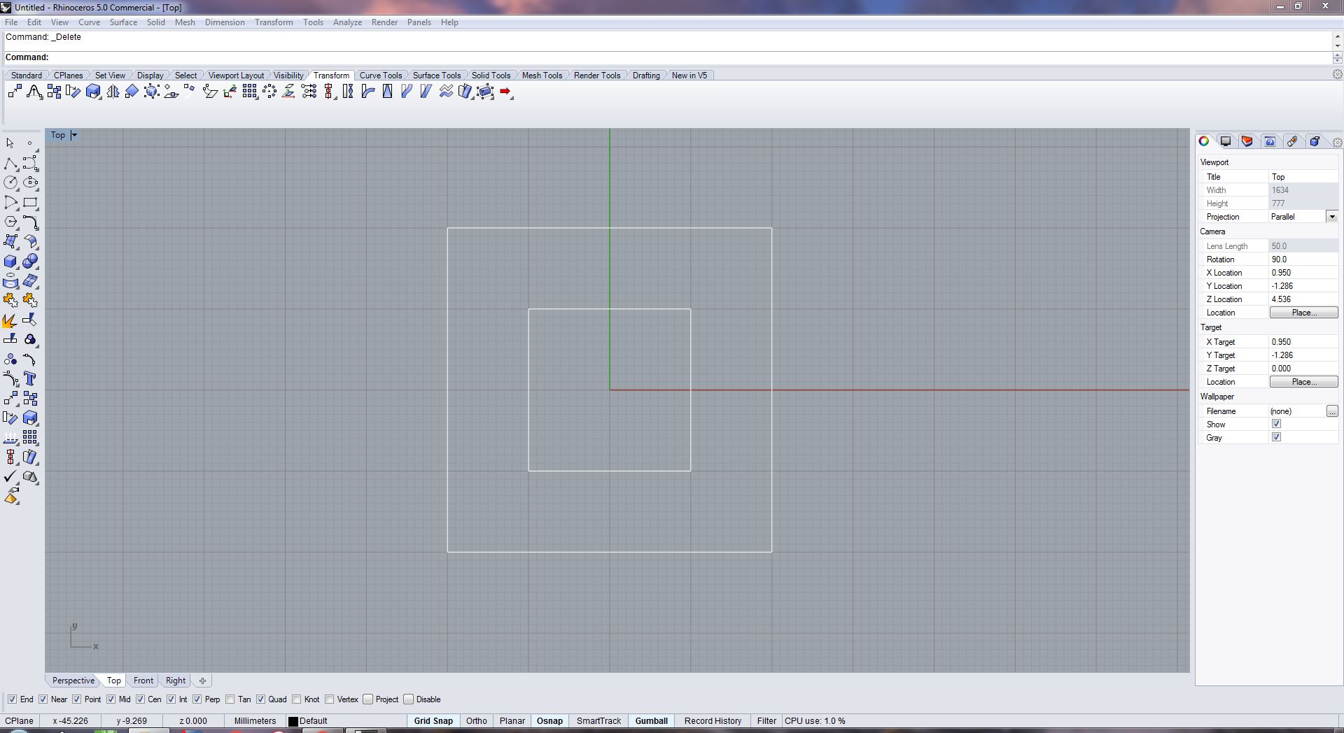
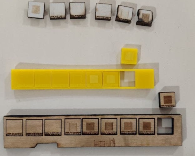
Design for testing kerf¶¶
We decided to make a simple design of a square with a 20mm side within a square with a 40mm side to calculate kerf. We began to draw the design within Rhinoceros 3D because the design is very basic.
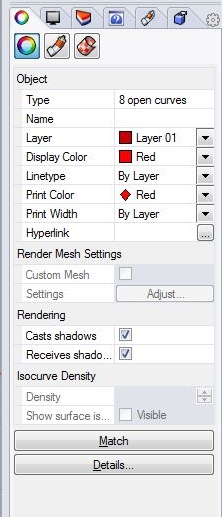
Design properties¶¶
The Layer attributes (side ribbon) were set up as, Display color as Red, Linetype as continuous, Print color as Red, Print width as hairline
Setting up Cutting/Engraving properties¶¶
We’ll use Ctrl+p to redirect to print properties, where we’ll make sure the print settings are set to 1:1 and the design is in the pintable region, before moving on to cutting/engraving parameters. If this is not the case, take appropriate action.Now select the printer as Trotec After being sent to the TROTEC Job Control window, we may pick the presets for different materials on the top ribbon, then click the highlighted button to change the settings further. Make any necessary modifications, and then drag and drop the design to the task area and put it where the cut would be done; if it is brought to the head pointer, it will automatically snap to it.
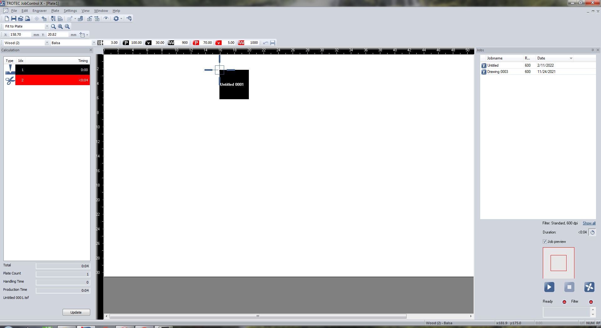
Cutting Parameters used¶¶
We created a file as shown below and adjusted the settings in the job control to find the best cutting parameters for each material, maintaining power constant and speed ranging from 100cm/sec to 20cm/sec for engraving and 1cm/sec to.2cm/sec for cutting *the values may change as per the meterials used.
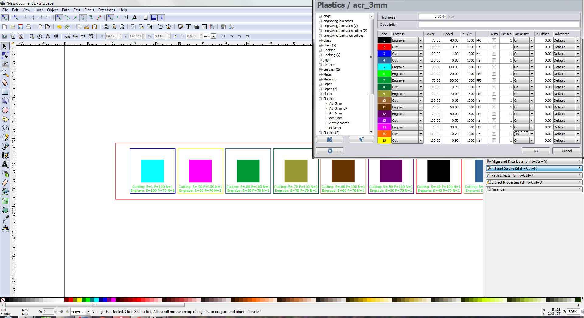
The materials were cut to determine the value for producing the best cut, however, the values provided for the cardboard were a little too high, so we increased the speed to 1 for cutting.
- AcrylicCutting Power=100Engraving Power=70Cutting Speed=0.4cm/secEngraving Speed=60cm/secNumber of passes=1Frequency=1000
- WoodCutting Power=100Engraving Power=70Cutting Speed=0.2cm/secEngraving Speed=60cm/secNumber of passes=1Frequency=1000
- CardbordCutting Power=100Engraving Power=70Cutting Speed=1cm/secEngraving Speed=60cm/secNumber of passes=1Frequency=1000
Test and Calculation¶¶
We measured the inner diameter of the square hole within the cutout component using a digital vernier, then the exterior dimension of the removed piece.
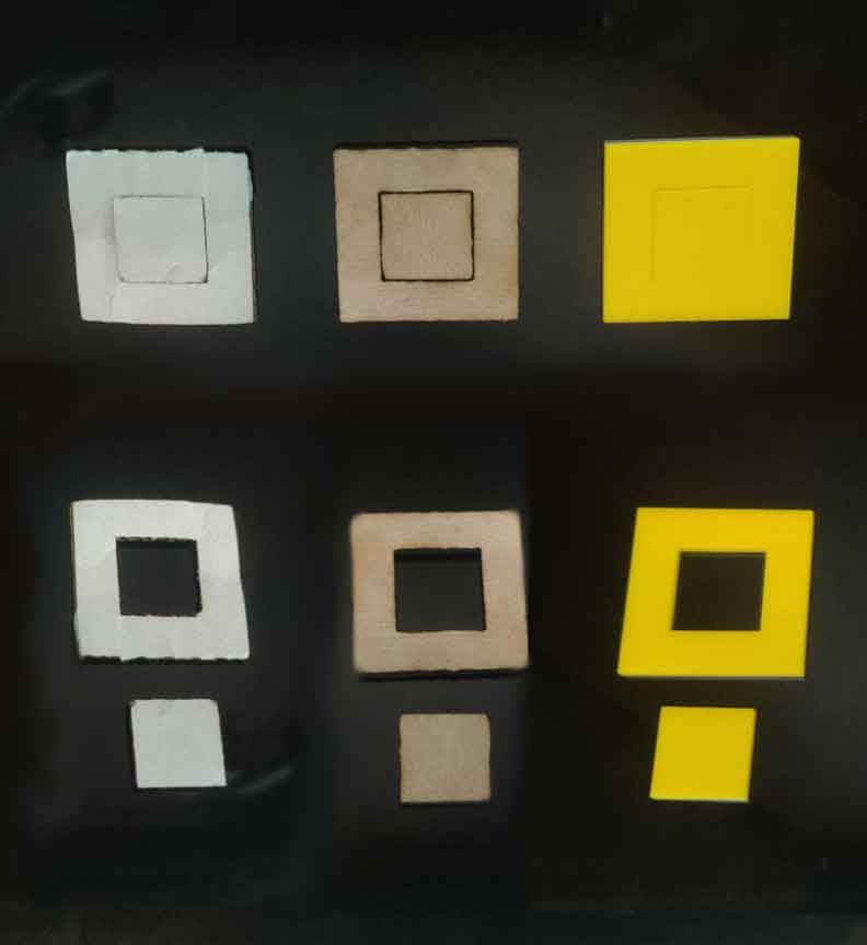
Now we can determined kerf by subtracting the inner from the outer dimension and then dividing by two.
- Acrylic20.20-19.87= 0.33kerf=0.33/2kerf=0.165
- Wood20.41-19.8= 0.61kerf=0.61/2kerf=0.305
- Cardbord20.35-19.84= 0.51kerf=0.51/2kerf=0.255
Metal Engraving¶¶
We tried engraving on a metal PCB board with the Trotec 400 flexx, experimenting with different engraving parameters and discovered that PCB prints at power 100 and speed 10cm/sec with 20 passes * for both cutting and engraving we need to select Cut FLP and Engrave FLP respectively
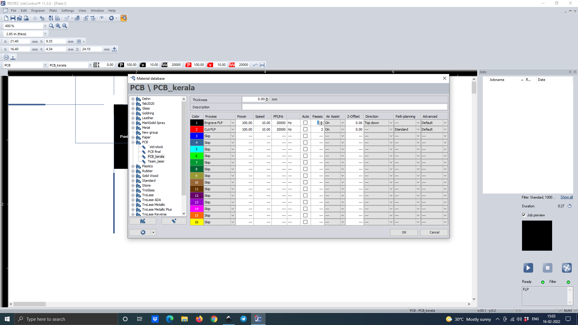
These are the results we got
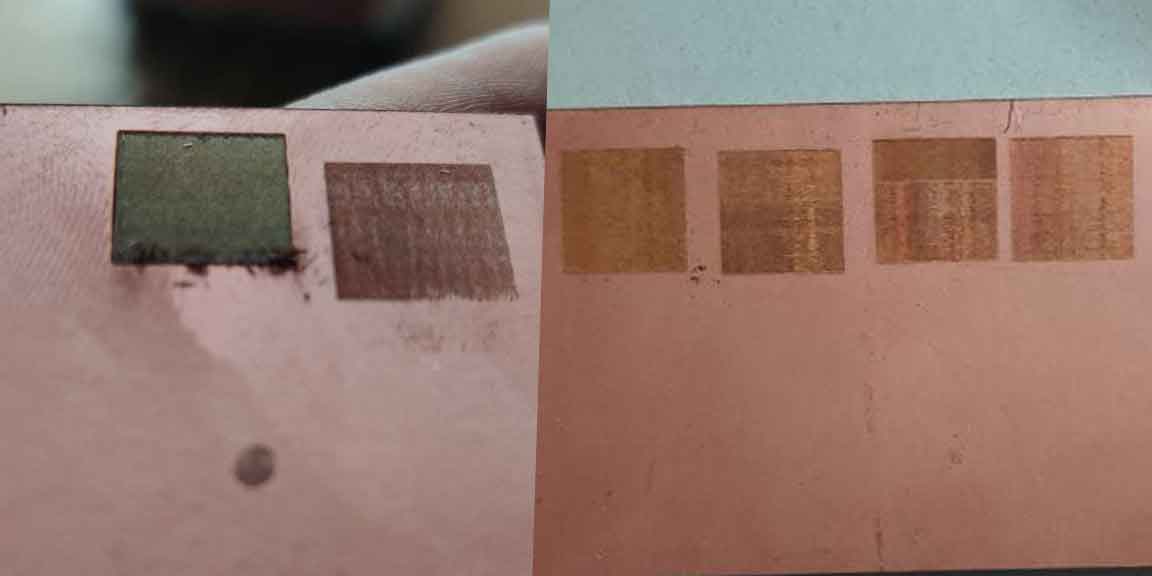
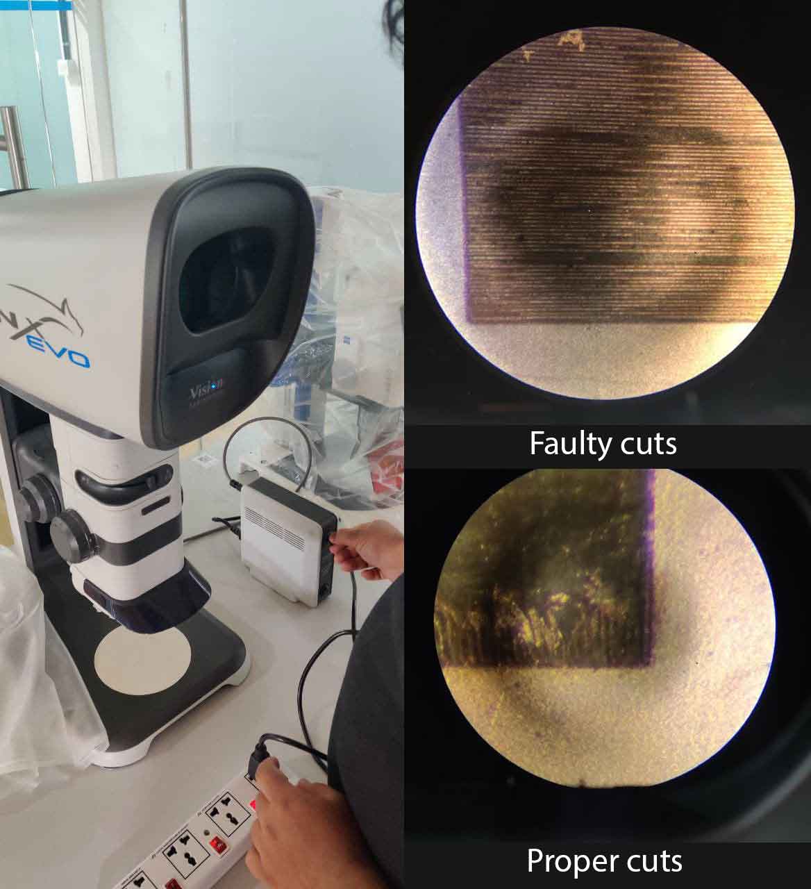
We used a 3D stereo microscope called the Lynx EVO to examine the cut. We discovered that faulty cuts make lined patterns, but proper cuts provide a smooth surface, and that we must clean the edges.
Download design files from here → Download