13. Input devices.
Task: Input Devices
The second half of the Fab Academy programme is designed to build on the previous weeks. You will be synthesisinginformation and implementing skills that you were introduced to in the first half of theprogramme and encouraged to integrate these into your final project proposal.
- Group assignment:(Page Link is Here)
- Probe an input device(s)’s analog and digital signals
- Document your work to the group work page and reflect on your individual page what you learned
- Individual assignment:
- Measure something: add a sensor to a microcontroller board that you have designed and read it.
In this week I can learn about the details of different input devices and it’s connection, coding and it’s working principle.
What is an input device?
An input device responds to changes in the environment and produces a suitable electrical signal for processing in an electronic circuit.
In all input devices, other forms of energy are transformed into electrical energy.
My plan was use a load cell in this week. But it is not available in the inventory.
So I decided to explore some other sensors/ input devices in this week.
Potentiometer and joystick
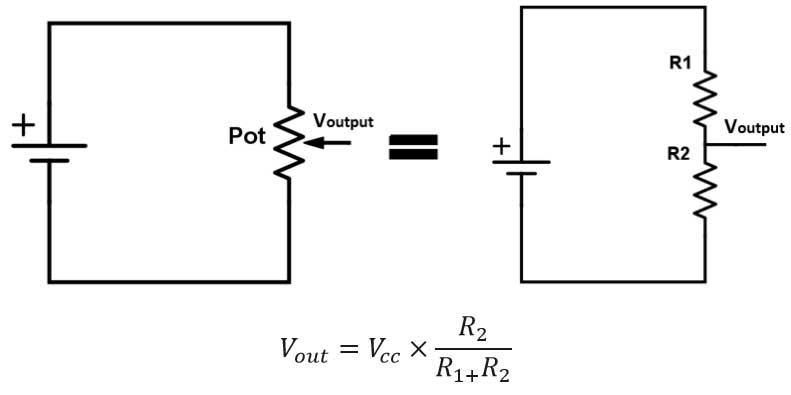
A potentiometer is a manually adjustable variable resistor with three terminals. In our circuits we use it as a voltage divider. Basically, the voltage divider is used to turn a large voltage into a smaller one.
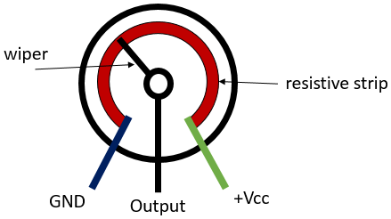
A wiper moves and it divides the resistive strip as a parallel circuit. And then we can get different voltage in the output pin according to Ohm’s Law.
Some uses of potentiometer
- Use for volume controlling in audio equipment.
- Use as position transducers in Joysticks.
Potentiometer joystick
It contains two potentiometers, one for each axis. The two potentiometers allow us to measure the movement of the stick in 2-D. As we move the joystick, the value of resistance of both the potentiometers changes. This change, in turn, gives us values along the X and Y axes.
The joystick gives out an analog input that is voltage varying in the range of 0 and 5v. By default, the joystick will give a value in the range of 400-600 and the value will increase or decrease as we move the joystick around. ref: thestempedia.com

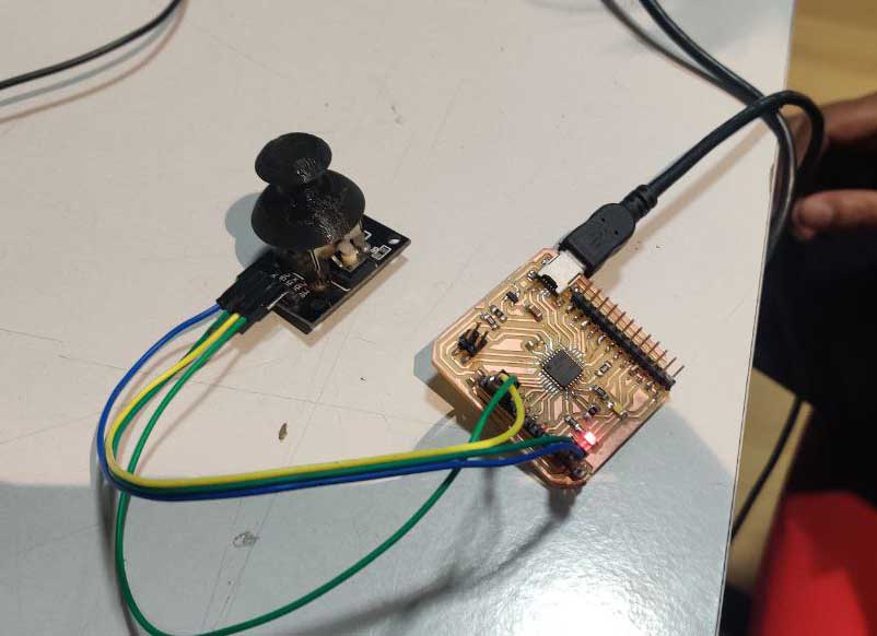
Connection
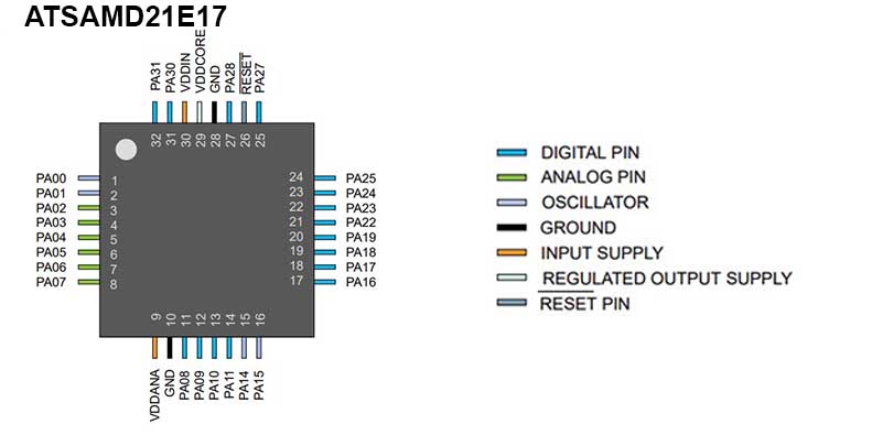
I have made a devkit board in the output programming week. I used that board this week.(Link to Board fabrication process)
For finding the pinout I referred to the datasheet and for the Arduino pin-map I used *Justin Mattair’*s Page(Link Here)
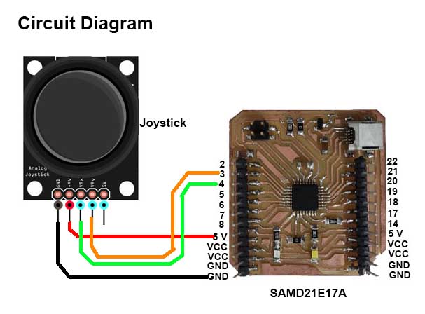
Using Joystick
Diagram
Programming
Steps
- Select SAMD21E17A board in Arduino IDE.
- Select COM port.
-
Coding.
```arduino void setup() {
SerialUSB.begin(9600); }
void loop() {
delay(1000);
if (analogRead(2)> 900) { SerialUSB.println(“Up”); } if (analogRead(2)< 200) { SerialUSB.println(“Down”); }
if (analogRead(3)> 900) { SerialUSB.println(“Right”); } if (analogRead(3)< 200) { SerialUSB.println(“Left”); } } ```
This code is for printing different directions according to the movement of the joystick.
I used the if statement for each direction according to different analog readings. Jowshin helped me to write this code.
-
Uploading
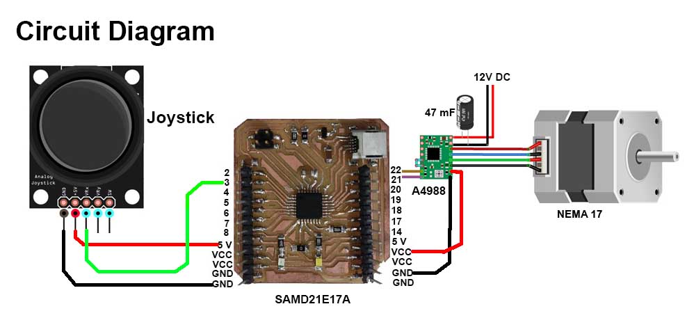
Control stepper motor with joystick
Connection
Code
const int stepPin = 23;
const int dirPin = 22;
int customDelay,customDelayMapped;

void setup() {
  pinMode(stepPin,OUTPUT);
  pinMode(dirPin,OUTPUT);

  digitalWrite(dirPin,HIGH);
void loop() {

  customDelayMapped = speedUp();
  digitalWrite(stepPin, HIGH);
  delayMicroseconds(customDelayMapped);
  digitalWrite(stepPin, LOW);
  delayMicroseconds(customDelayMapped);
}

int speedUp() {
  int customDelay = analogRead(2);
  int newCustom = map(customDelay, 0, 1023, 300,4000);
  return newCustom;
}
Working
I also tested some more sensors.
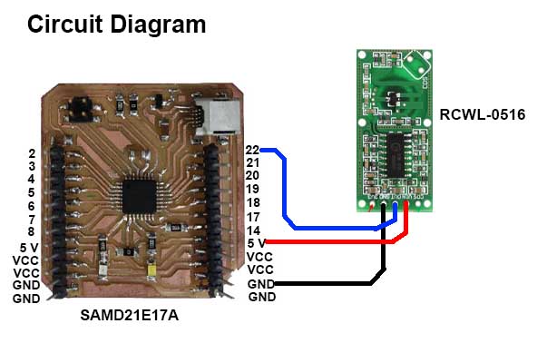
RCWL-0516
It is a proximity sensor that uses Dopler Radar to sense the presence of an intruder.
How it works?
The sensor emits microwaves and analyses the reflected waves to check for any changes
Connection
Code
int inPin = 23;

void setup()
{
  pinMode(inPin, INPUT);
  SerialUSB.begin(9600);

}

void loop()
{
  int reading = analogRead(inPin);
  SerialUSB.println(reading);

  delay(500);
}
Testing
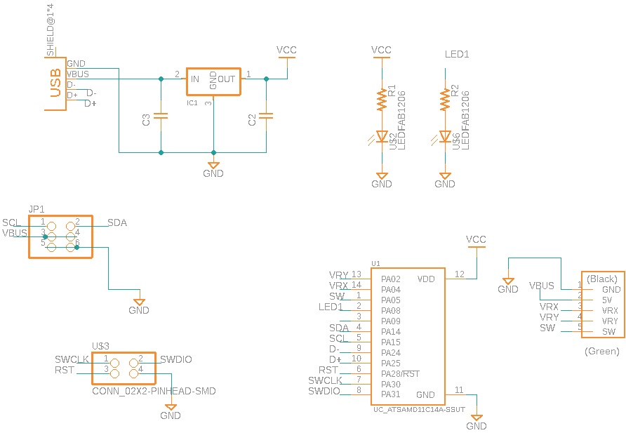
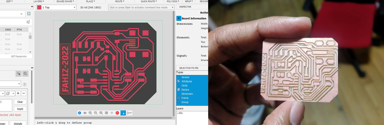
Making a new board for joystick
I designed a board with joystick and SAMD11c. I also leave pins for i2c communication(SDA, SCL, VCC and GND). So I can use this board for communication week also.
Schematic
Routing and milling
It worked with the same code I used before.
Bill of materials
| Part | Value | Device | Package | Description | AVAILABILITY | DESCRIPTION | MF | MP | PACKAGE | PRICE | PURCHASE-URL |
| C2 | 10 mF | CAP_UNPOLARIZEDFAB | C1206FAB | ||||||||
| C3 | 10 mF | CAP_UNPOLARIZEDFAB | C1206FAB | ||||||||
| IC1 | 3.3 V 100 mA | VR_REGULATOR-SOT23SOT23 | SOT23 | ||||||||
| JP1 | CONN_03X2-PINHEAD-SMD | 2X03SMD | PIN HEADER | ||||||||
| R1 | 499 ohm | R1206FAB | R1206FAB | Resistor (US Symbol) | |||||||
| R2 | 499 ohm | R1206FAB | R1206FAB | Resistor (US Symbol) | |||||||
| U$1 | CONN_USB_MINIB | CONN_USB_MINIB | USB_MINIB | ||||||||
| U$2 | LEDFAB1206 | LEDFAB1206 | LED1206FAB | LED | |||||||
| U$3 | CONN_02X2-PINHEAD-SMD | CONN_02X2-PINHEAD-SMD | 2X02SMD | ||||||||
| U$4 | 5-PIN | 5-PIN | 1X06SMD | ||||||||
| U$6 | LEDFAB1206 | LEDFAB1206 | LED1206FAB | LED | |||||||
| U1 | UC_ATSAMD11C14A-SSUT | UC_ATSAMD11C14A-SSUT | SOIC127P600X160-14N | MCU 32-Bit SAM D11 ARM Cortex M0+ RISC 16KB Flash 1.8V/2.5V/3.3V 14-Pin SOIC T/R Check prices | In Stock | ARM® Cortex®-M0+ SAM D11C Microcontroller IC 32-Bit 48MHz 16KB (16K x 8) FLASH 14-SOIC | Microchip | ATSAMD11C14A-SSUT | SOIC-14 Microchip | None | https://pricing.snapeda.com/search/part/ATSAMD11C14A-SSUT/?ref=eda |