6. 3D Scanning and printing
Task: 3D Scanning and Printing
- Group assignment:(Page Link is Here)
- Test the design rules for your 3D printer(s)
- Document your work and explain what are the limits of your printer(s) (in a group or individually)
- Document your work to the group work page and reflect on your individual page what you learned
- Individual assignment:
- Design and 3D print an object (small, few cm3, limited by printer time) that could not be easily made subtractively
- 3D scan an object, try to prepare it for printing (and optionally print it)
It is the week we can study to turn our ideas into our hands.
In this week, I can study the technique of turning design into reality.
My goals:
- Learn to 3d print a design file.
- 3d scanning
3D printing.
3D printing, also known as **additive manufacturing**, is a method of creating a three-dimensional object layer-by-layer using a computer-created design. 3D printing is an additive process whereby layers of material are built up to create a 3D part.
Ref: twi-global.com
Creating a design
Fab academy recommends to make a additive only design or a print on place design. That design we cannot make using any milling or molding method.
I refer some previous designs and something from internet also.
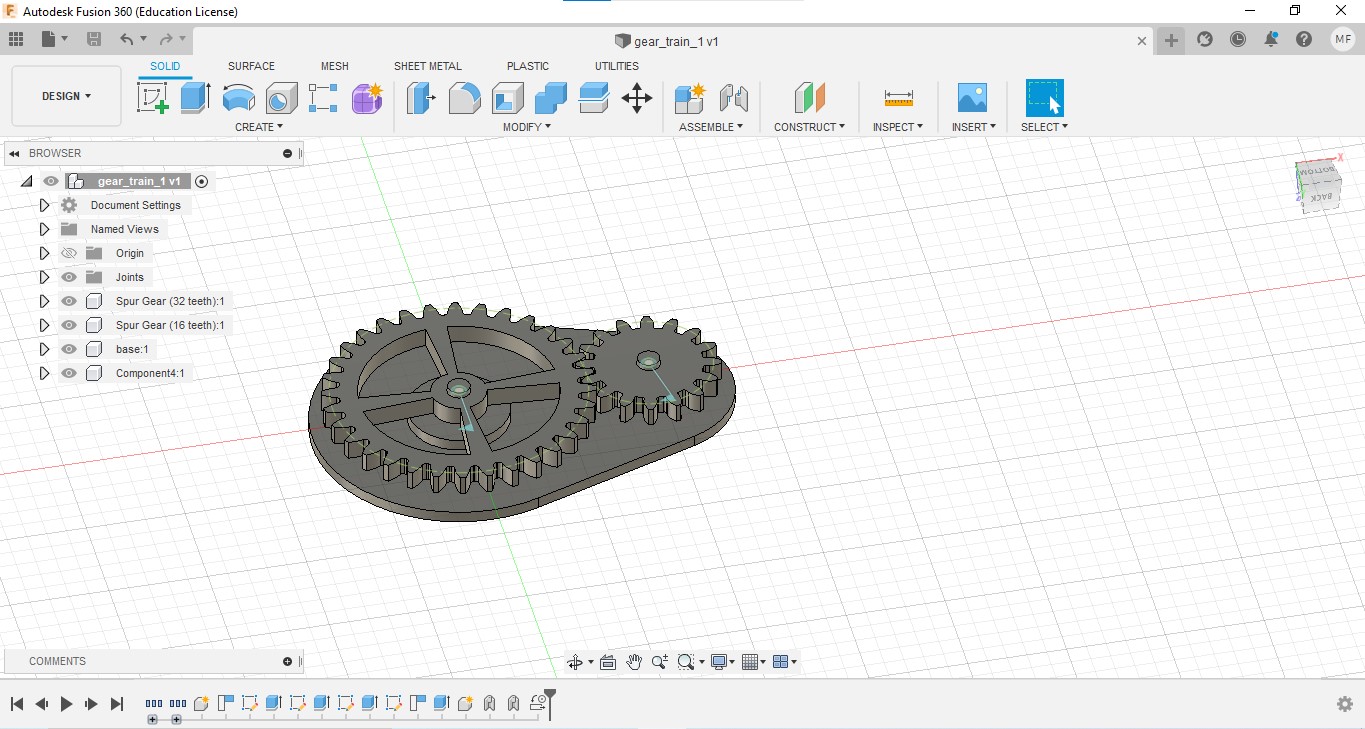
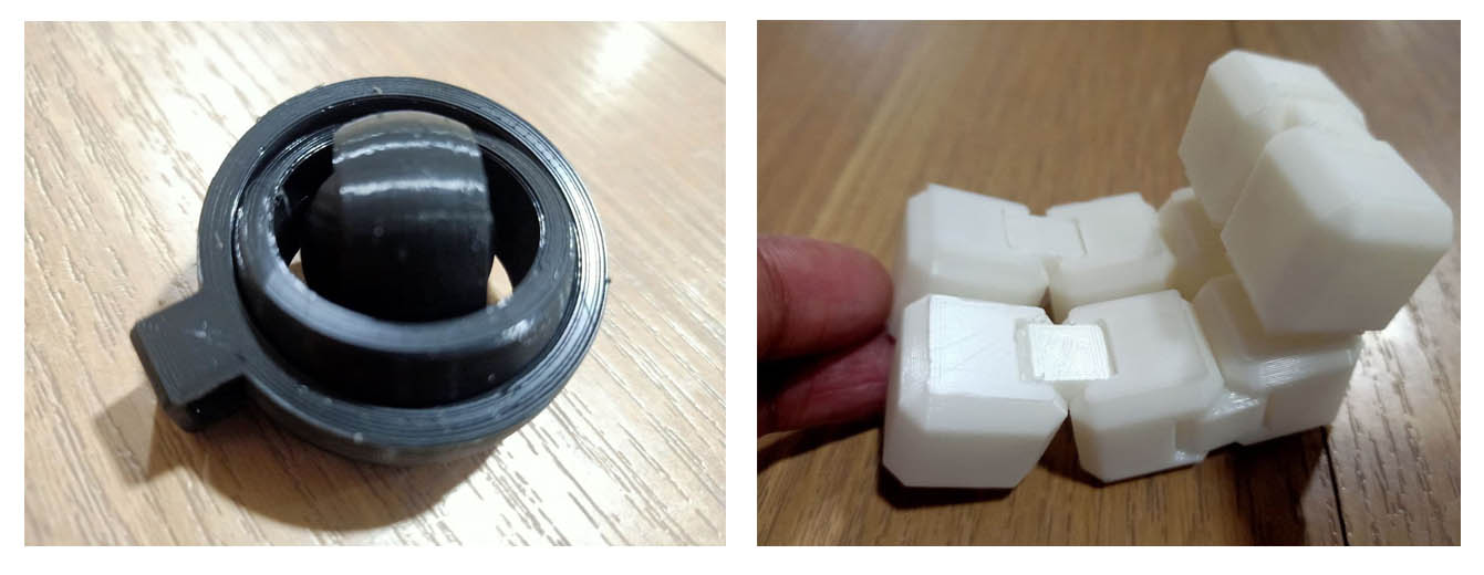
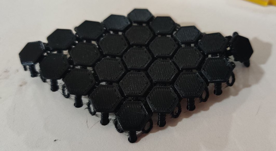
Then I desided to make a gear train mechanism and an infinity cube.
Our instructors recommended to make some designs using Rhino grasshopper.
I could study many things in Fusion 360 and Rhino grasshopper.
Important tips to 3d print a print on place
- Give optimal clearance between joints and adjacent parts according to the print rule of the printer.
- Give fillet or chamfer in the corners.
-
Avoid overhanging maximum if possible, If not, give a more clearance. We can orient the model with minimum overhanging in slicer software.
ref: all3dp.com
I tried to create maximum moving parts which will be print on place. I used design rules I studied from the group assignment.
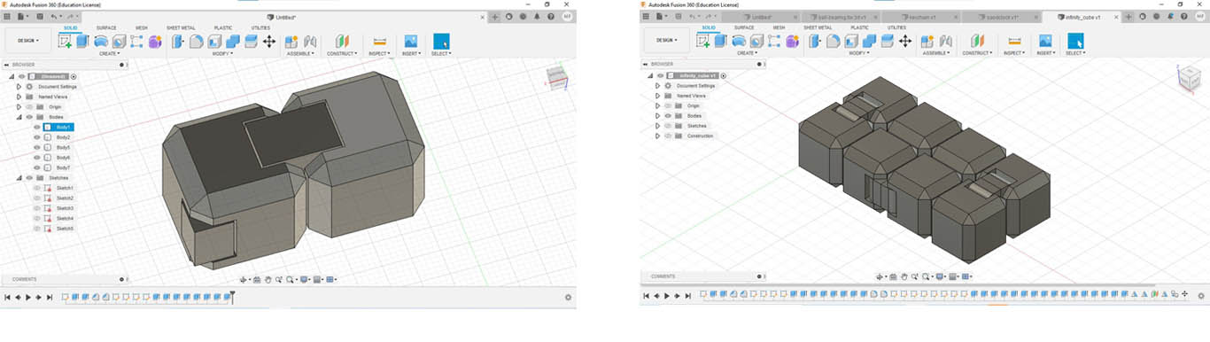
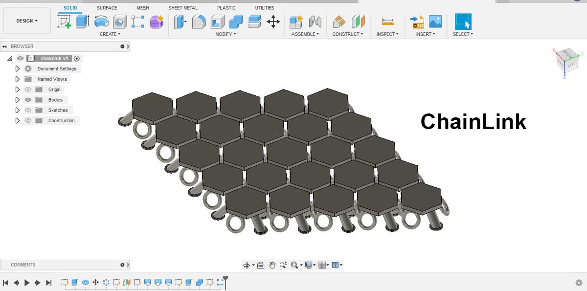
some other designs I have tried
After designing save the file in stl format.
Slicing.
As mentioned above, a 3D printer prints a design layer by layer.
What does G code mean?
G-code is a programming language for CNC (Computer Numerical Control) machines. G-code stands for “Geometric Code”. We use this language to tell a machine what to do or how to do something. The G-code commands instruct the machine where to move, how fast to move and what path to follow
Each line of a g code is known as a block.
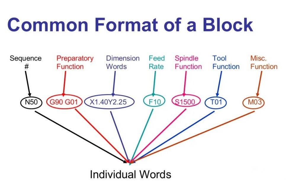
ref: slideshare.com
For converting our design into gcode format, we use slicer software.
Prusa slicer
PrusaSlicer is an opensource tool for Original Prusa 3D printer.
Steps
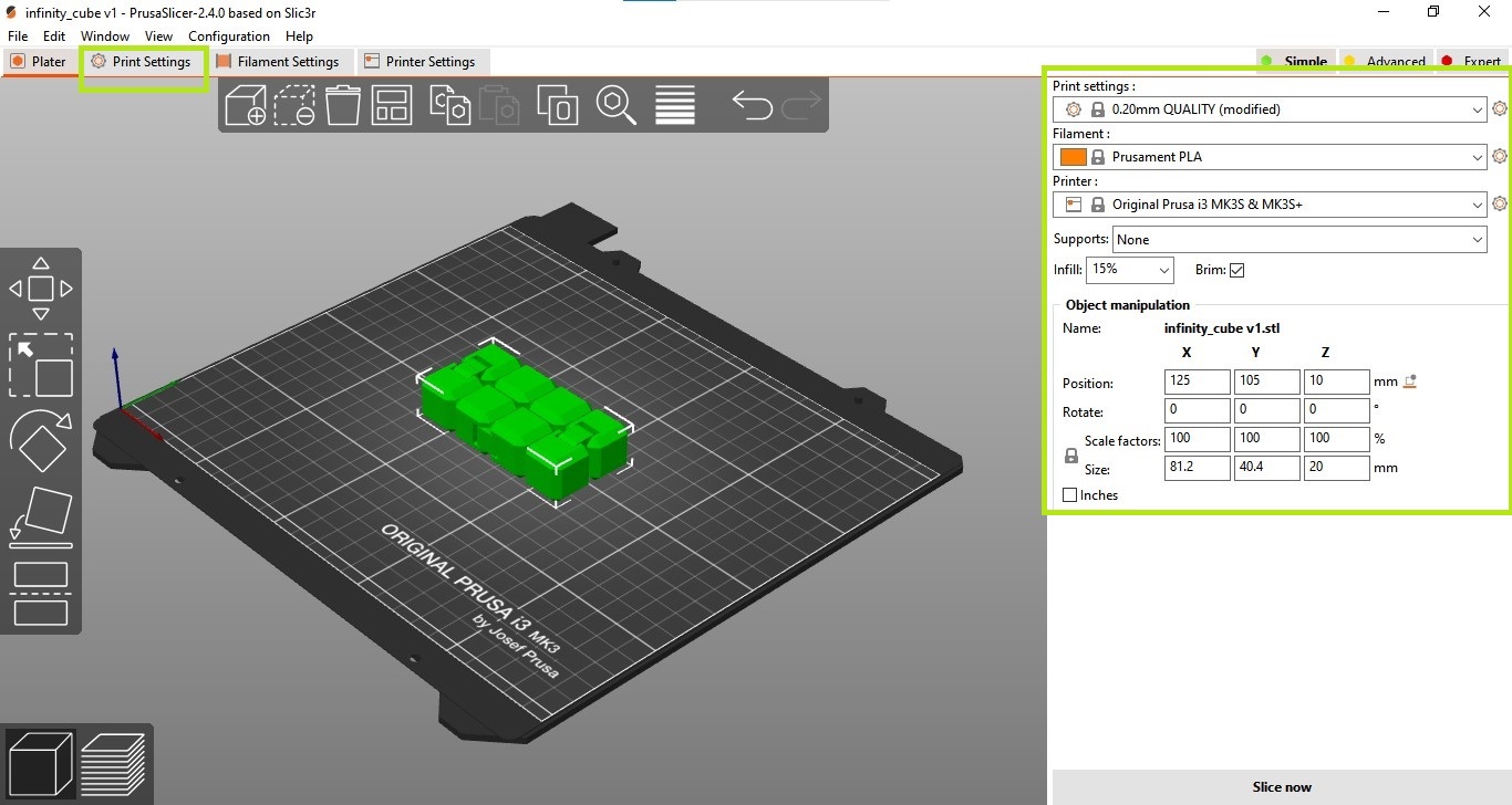
- Open PrusaSlicer 2.3.3 software and select the printer model, Original Prusa i3 MK3S & MK3S+
- Go to File → Import → Import STL/OBJ and select the stl file from the computer.
-
In the right column, select Print settings: 0.20 mm QUALITY Filament: Prusament PLA Supports: None Infill: 15 % Tick on Brim
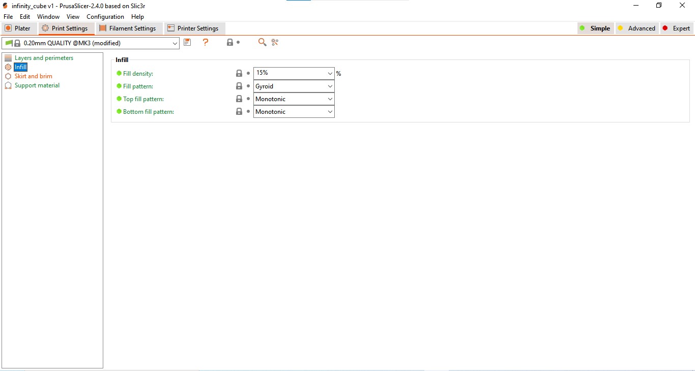
-
Click on Print settings: Here we can adjust many print settings like infill, support, etc. Go to Infill and set Infill properties (Fill density, Fill pattern, etc.) Go to Support material, from here we can add support material or skip it.
-
Click on Slice now. After slicing, Printing time and filament length and other details will display.
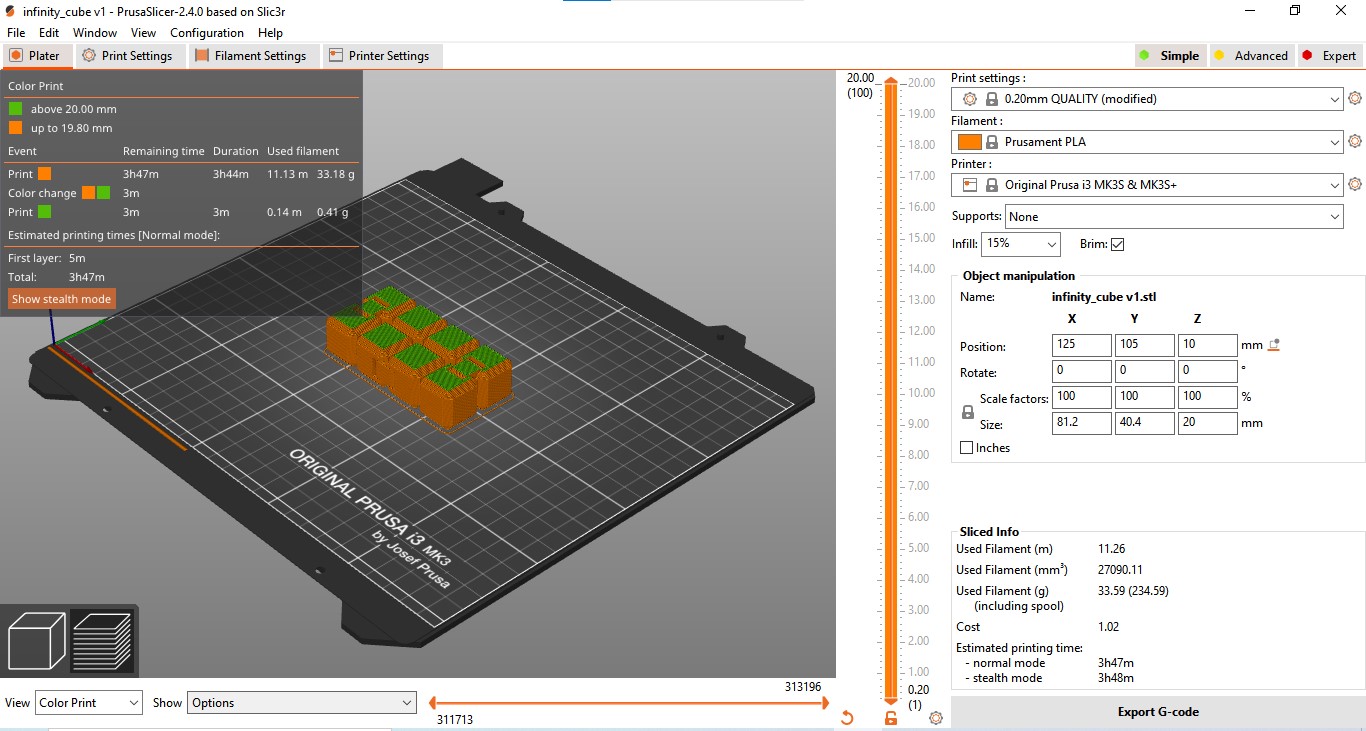
-
Click on Export G-code and save the file.
Now g-code file of the design is ready. copy it to a memory card.
Setting Up the 3D printer
Insert memory card.
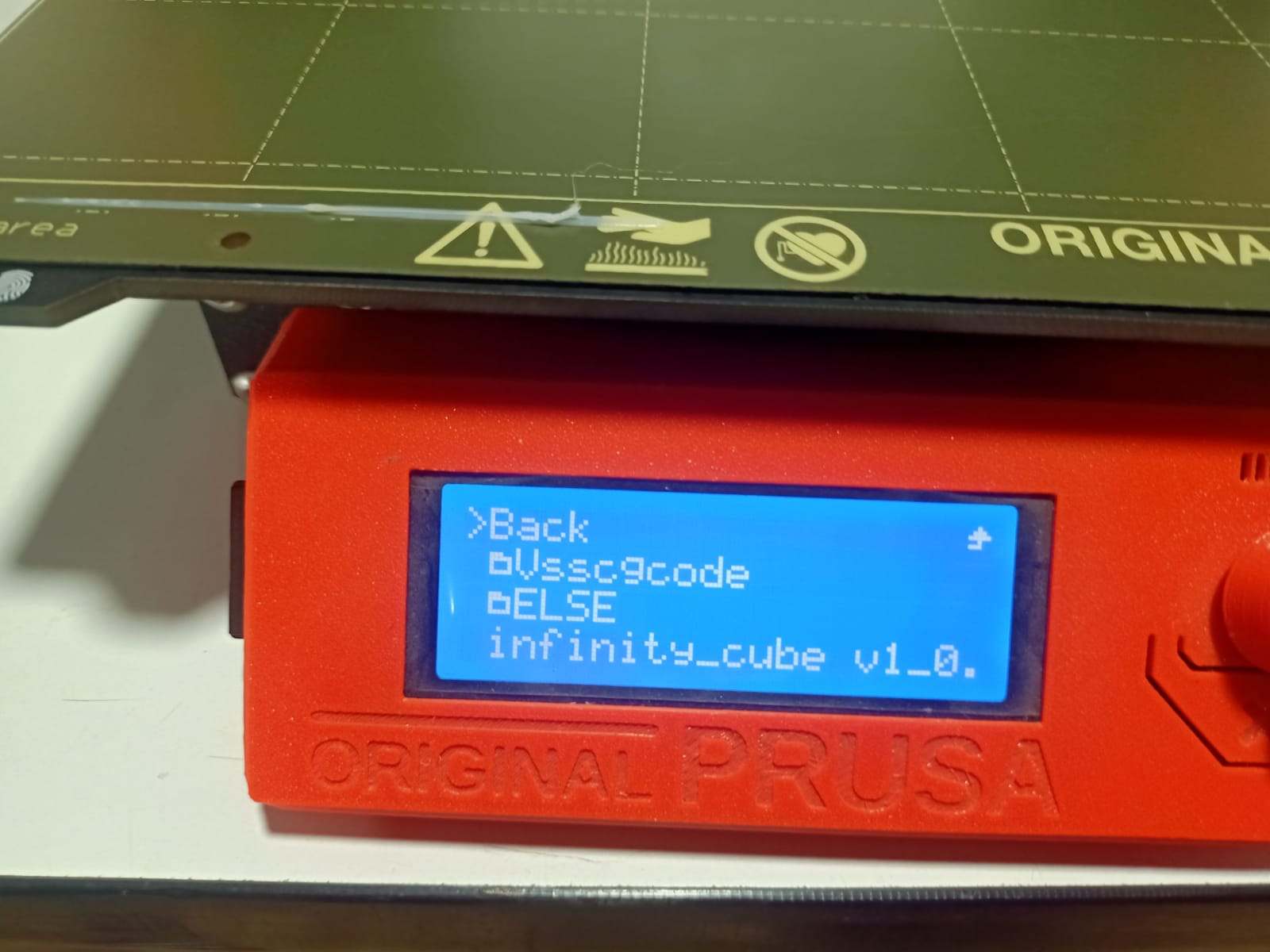
The window will display files in the SD card. If not, go to Print from SD
By rotating the knob, we can select our file. then click on the knob.
Then the printer will automatically do
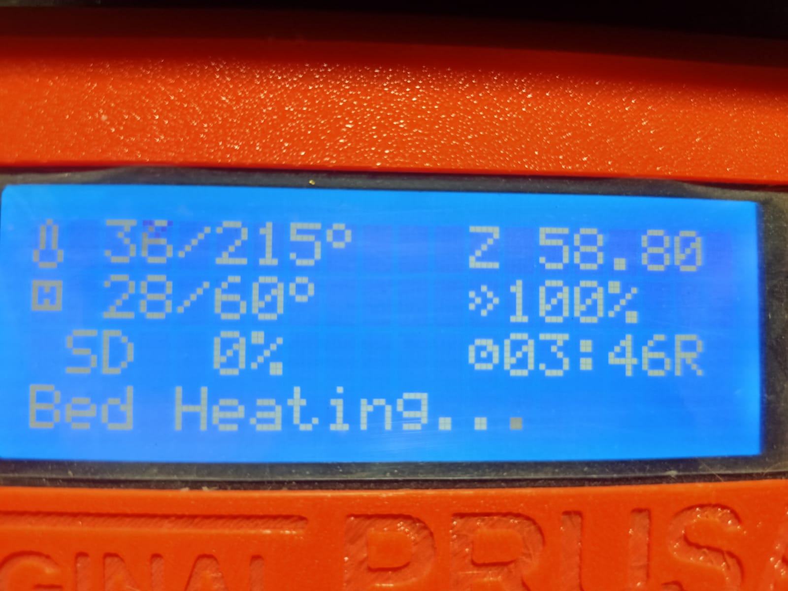
Heating the knob and plate
Performing the mesh bed leveling.
Cleaning the nose of the knob with an intro line in the front edge.
Starting the print.
The time for printing will be shown in the window.
In the beginning, I noticed that one side of my print detached from the plate. and there was an extra deposit in one position,
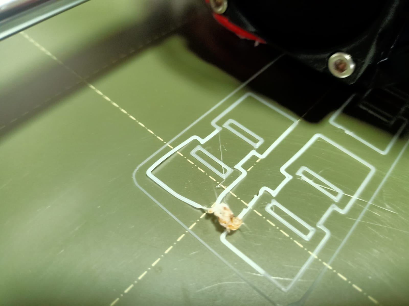
With the help of our instructor Joel Alex, I solved the problem. I increased the nozzle temperature from 215 to 220 degrees Celsius and adjust the Z-axis.
- To adjust carrier temperature Go to Menu → Tune → Nozzle and increase temperature.
- To adjust Z-axis Go to Menu → Live adjust Z
- The reason for the deposition of extra material is that I didn’t have remove the intro line of the last print.
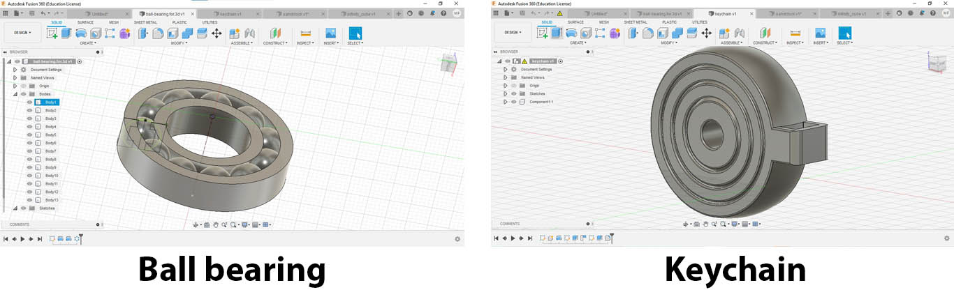
Objects I 3D printed(Keychain,
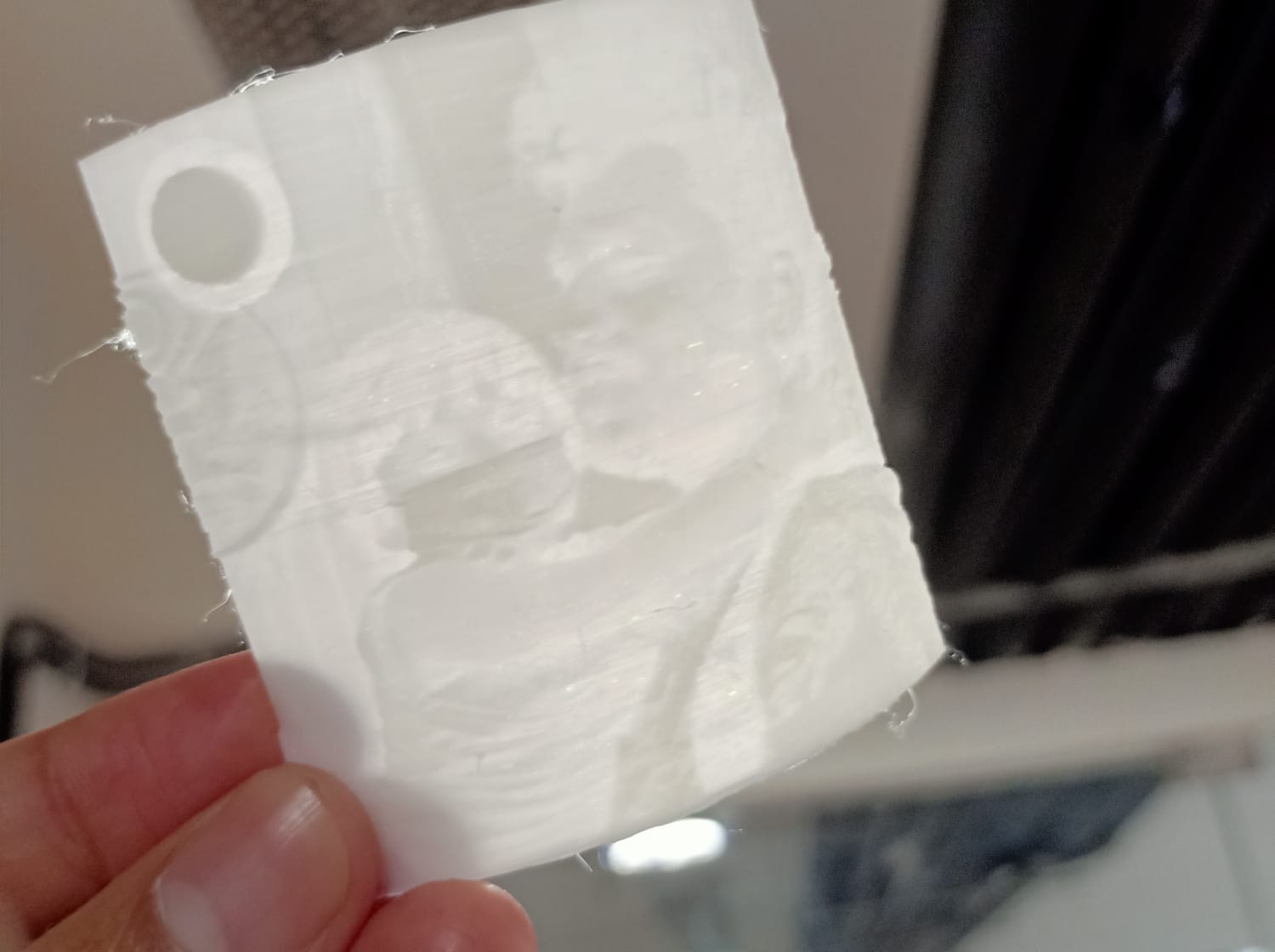
3nd print: Lithophane.
I am waiting from the start of the fab academy course to 3d print a Lithophane.
I upload a photo of my friend in 3dprocks/lithophane and download the stl file. and sliced by prusaslicer.
Then I started printing, after 3 minutes, my print detached from the bed. Then I understood the importance of brim in 3d printing.
What is brim?
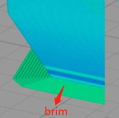
Brim is a layer flat area around the base of the model to prevent warping and to fix on the bed
I didn’t give any brim width to the model in the prusaslicer.
After giving a brim of 5 mm I repeated print.
Then I got the best result.
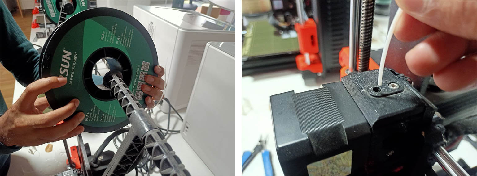
Changing the filament
It is a very simple process in Original Prusa i3 MK3S 3d printer
Steps:
- Go to Menu → Unload filament and press the knob, Then the nozzle will start to heat.
- Then press the knob and pull out the filament from the nozzle.
- Change filament roll, and clean the tip of the filament.
- push the filament through the hole.
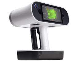
Artec 3D scanner.
How it works?
It operates by projecting light in a pattern, usually in the form of multiple parallel beams, onto an object. By projecting a grid pattern on the object, the scanners are able to capture the deformation or distortion from multiple angles and then calculate the distance to specific points on the object using triangulation
Benefits of Artec Leo model.
It is a handheld 3D color scanner with automatic, onboard processing.
It includes a touch screen panel so users can watch in real-time as a 3D replica of the scanned object comes to life. By rotating and zooming the model, the user can see if any areas were missed, thus allowing full coverage in one scan. Its acquisition speed is up to 3 million points/second.
ref: Wikipedia
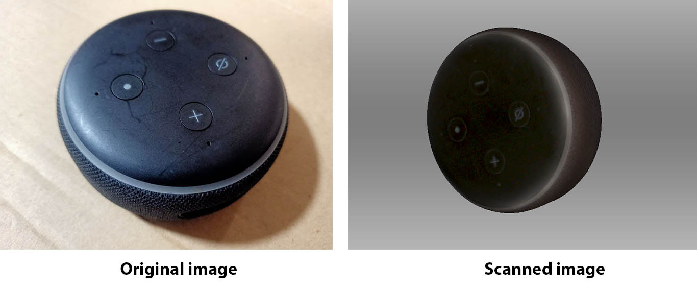
Scan object using Artec Leo
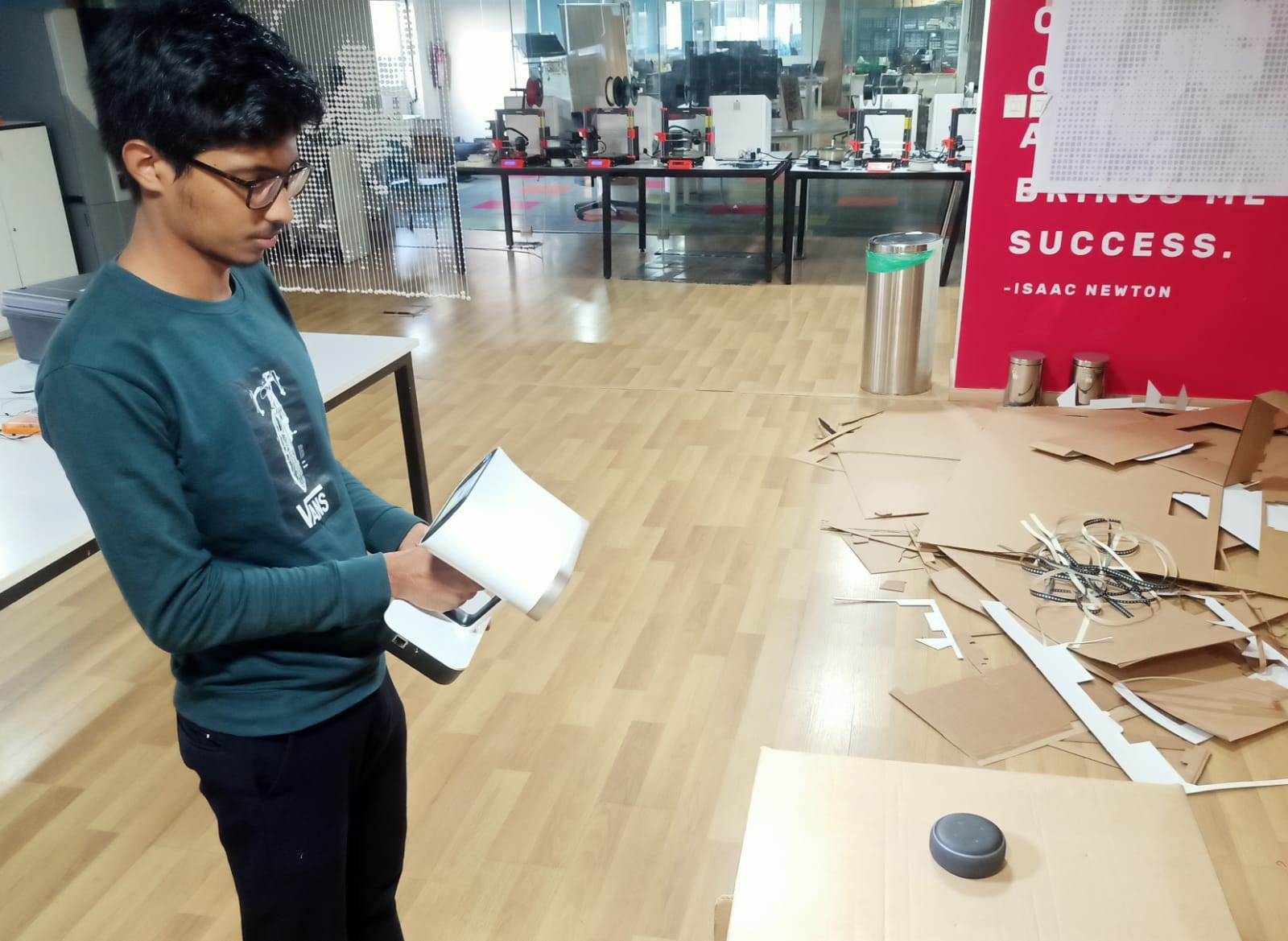
Steps I followed
- Place the object on a flat surface. I place the amazon Alexa on a cardboard box.
- Turn on Artec Leo.
- Click on the new project on the screen.
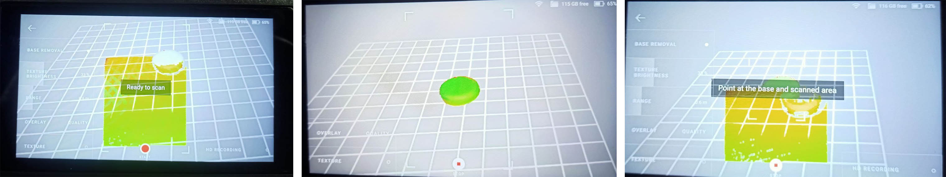
- Scan the base plane, That time we can adjust the focal length
- After displaying ready to scan, click on the switch and scan the object.
- We can see the missed areas in red color and rescan those areas.
- Then invert the position of the object and repeat scanning.
-
After finishing the scan, we can resume the scan at any time by selecting the project.
After scanning I imported the project file in the Artec studio
Connect the scanner and the computer using the land cable.
In Artec Leo scanner.
Go to Projects → Settings → Connect to Leo →
and turn on Wired(DHCP server) option.
In Artec Studio software
Go to File→ Import → Leo project and select the scanner and click on connect.
In the opening window, select the project.
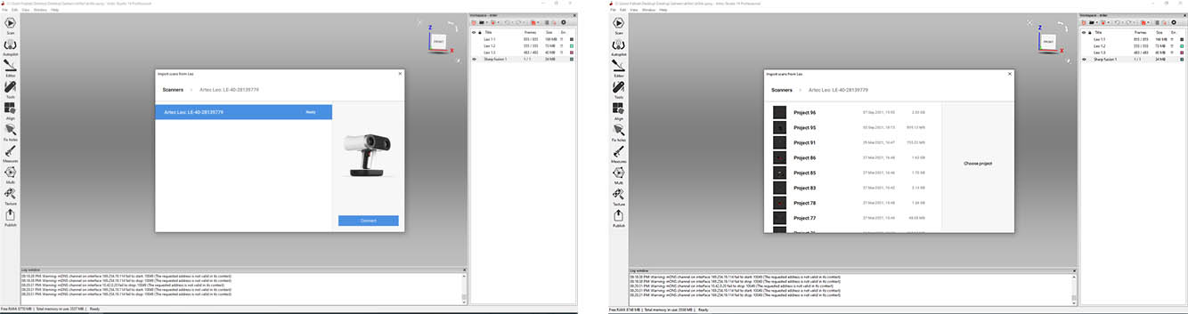
We can connect the scanner and computer by WIFI or land cable.
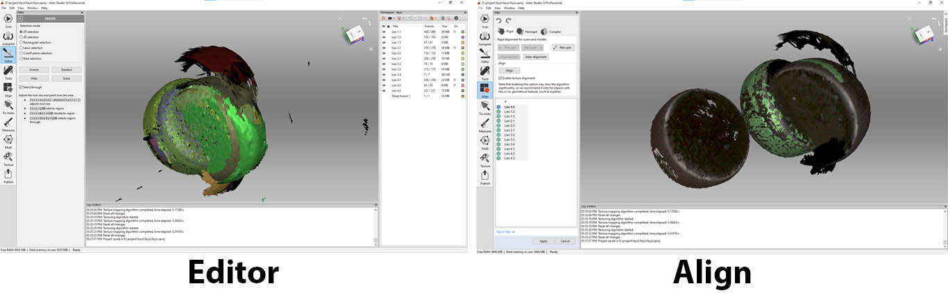
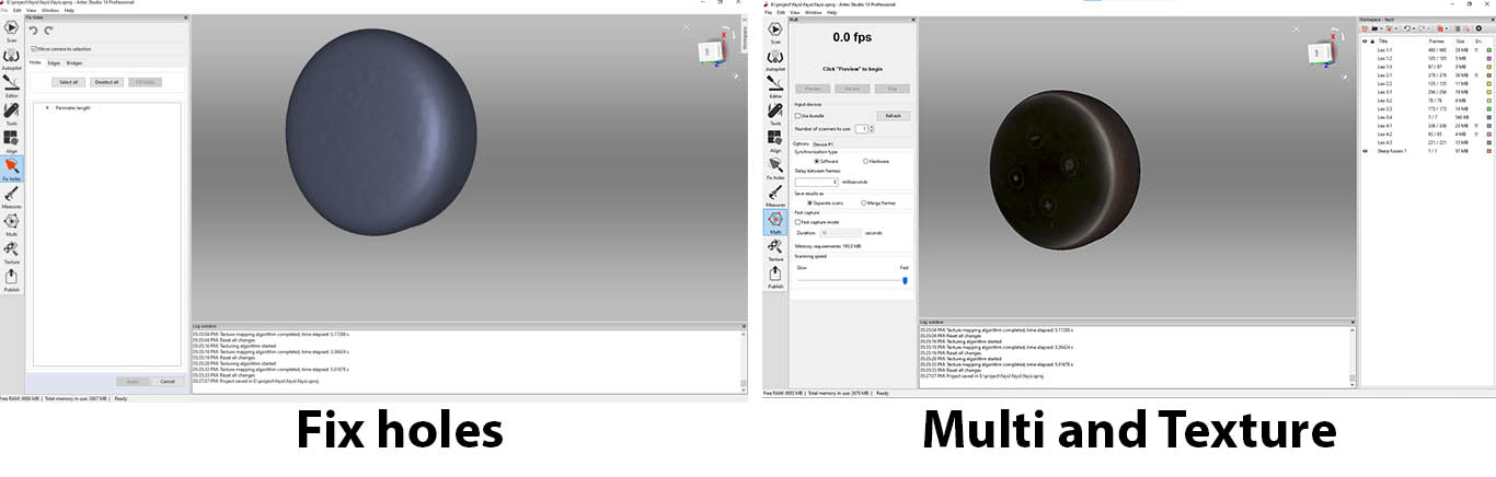
My object was in a symmetrical shape. So autopilot editing didn’t successfully work. So I edited by manual.
Group assignment:
Task: Finding the design rules for using 3d printer
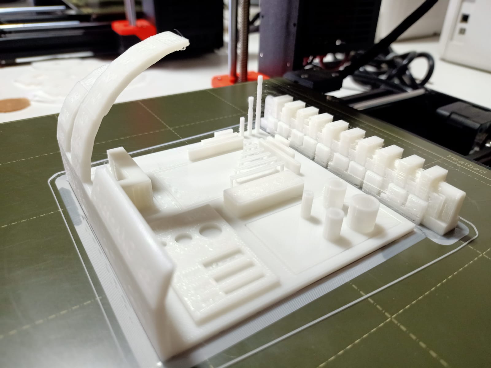
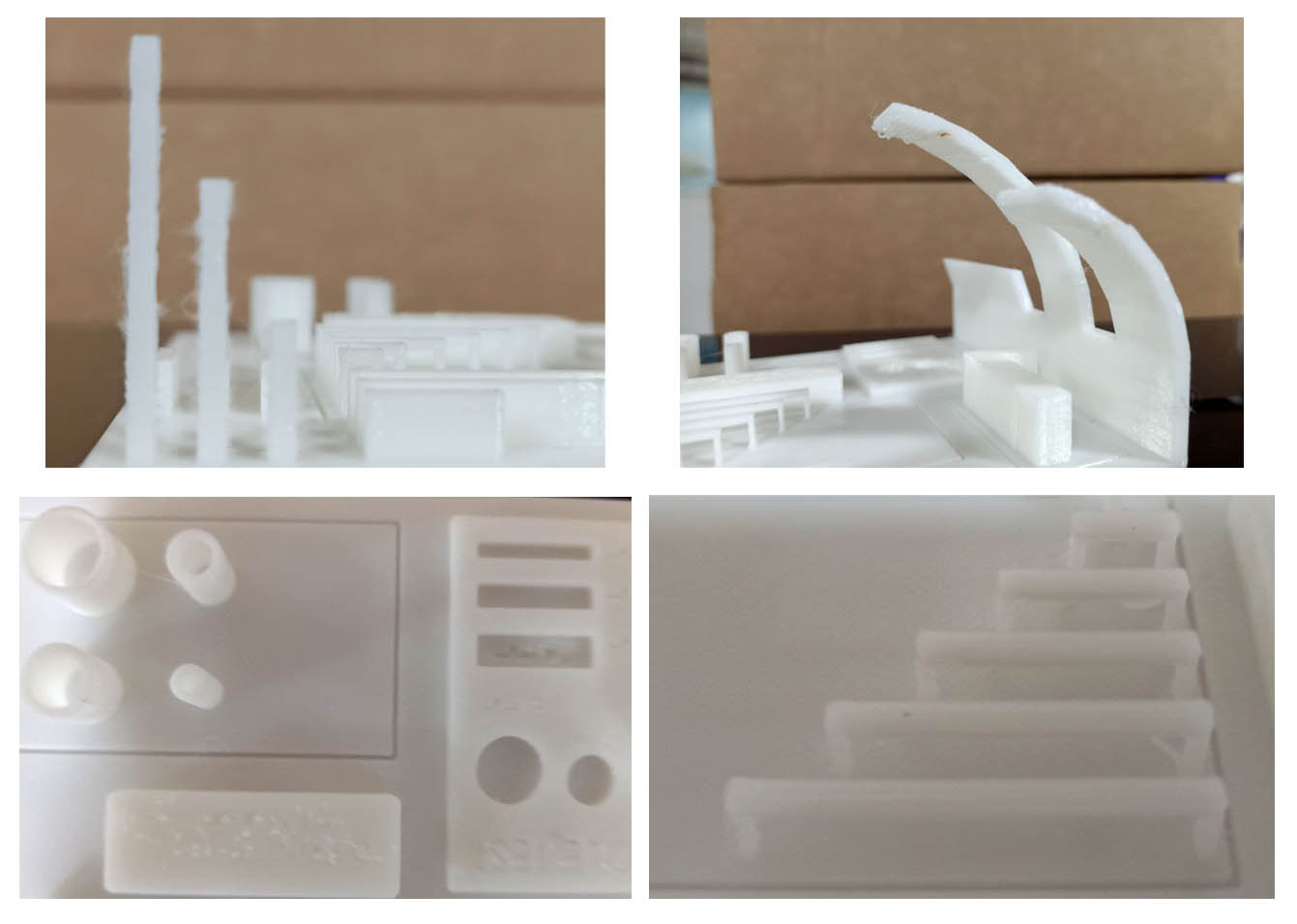
Overhang: Overhang is perfect up to 45 degrees. For the angles above 45 degrees, Some filament is deposited under.
Bridge width: Bridge width up to 25 mm is perfect.
Hole test, Diameter test: Hole test and diameter test for 1mm wall thickness was fine.
Tower height: We tested up to 20 mm tower height. After a height of 10 mm, there is a thread-like structure around towers.
Clearance test
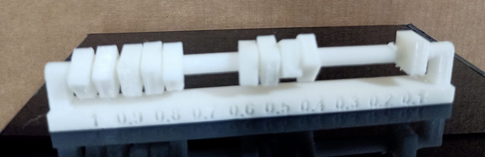
We tested from 0.1 mm to 1 mm with support.
minimum clearance for Original Prusa i3 MK3S is 0.2 mm.
For a joint, 0.3mm, 0.4 mm and 0.5 mm are recommendable
In 1 mm clearance, the ring was tight because of the support material in between.
Download design files from here → Download