11. Output devices
Task: Output Devices
- Group assignment:(Page Link is Here)
- Measure the power consumption of an output device
- Document your work to the group work page and reflect on your individual page what you learned
- Individual assignment:
- Add an output device to a microcontroller board you’ve designed and program it to do something
I was very exited about this week. Because I never operate a device using a microcontroller before fab academy. I operated some motors and some simple circuits. and that circuits didnt have any micro-controller.
In this week, I can learn to operate many devices like stepper motor, LCDs, OLEDs etc.
My project needs stepper motors. So I decided to study about stepper motors and DC motors in this output week as my assignment.
Stepper motor.
How a stepper motor works.
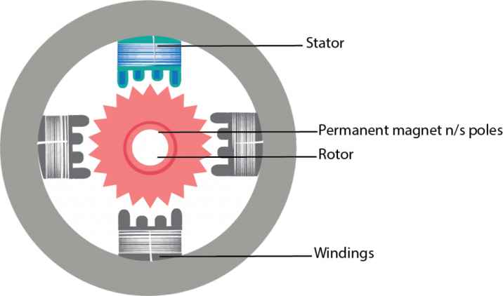
Stepper motors effectively have multiple “toothed” electromagnets arranged as a stator around a central rotor, a gear-shaped piece of iron. The electromagnets are energized by an external driver circuit or a microcontroller. To make the motor shaft turn, first, one electromagnet is given power, which magnetically attracts the gear’s teeth. When the gear’s teeth are aligned to the first electromagnet, they are slightly offset from the next electromagnet. This means that when the next electromagnet is turned on and the first is turned off, the gear rotates slightly to align with the next one. From there the process is repeated. Each of those rotations is called a “step”, with an integer number of steps making a full rotation. In that way, the motor can be turned by a precise angle. ref: Wikipedia
*Driving Modes*
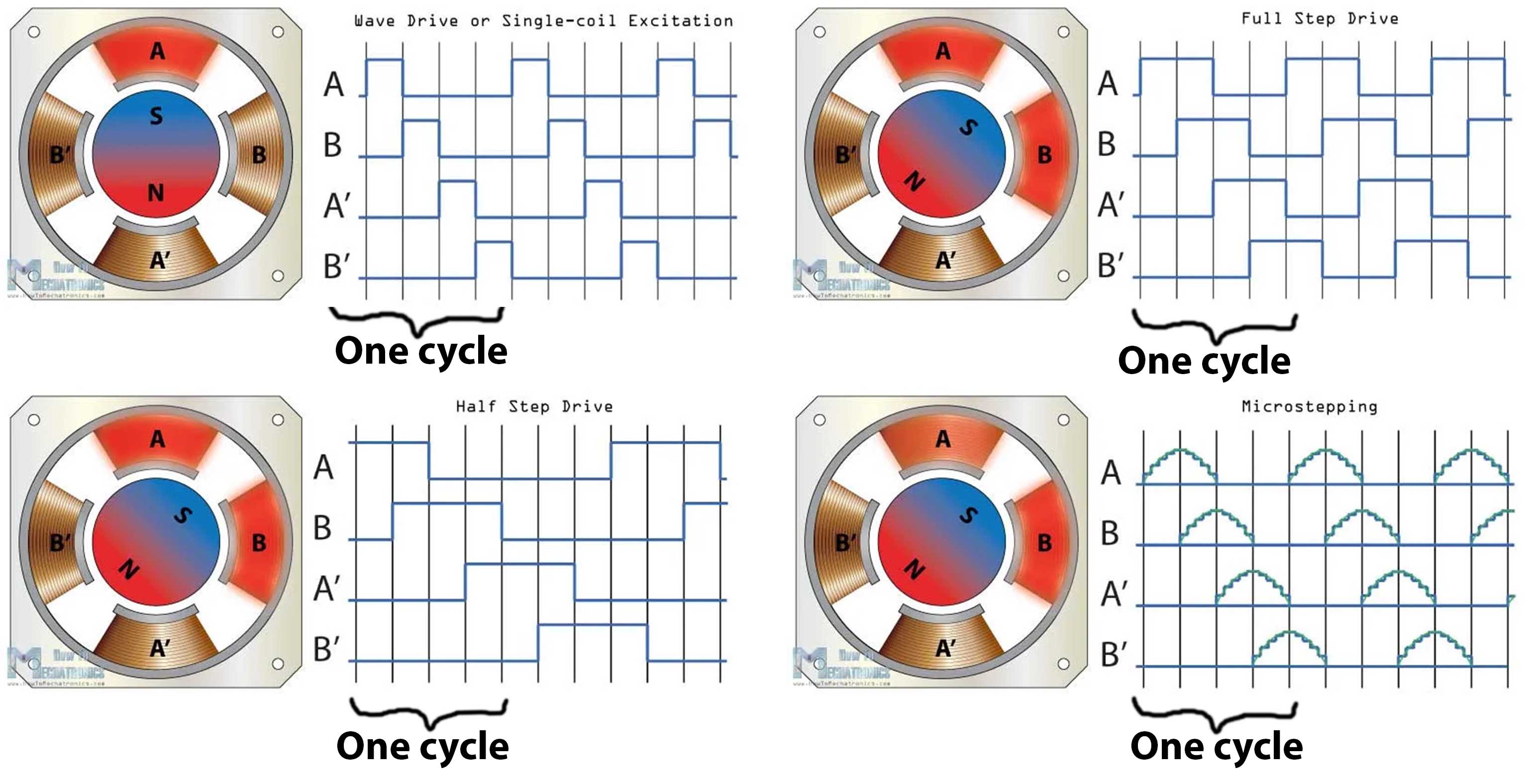
The above picture describes different driving modes of stepper motor.
We can rotate the rotor by activating different coils in different time and active different coils at one time.
img ref: howtomechatronics.com
Making a PCB.
I want to explore more output devices in this week. So I decided to make a board like Arduino. Our mentor Jogin recommended to make a board using ATSAMD21E17A
I refered some previous year boards (link here).
I added 24 pins which includes
- 4 VCCs
- 4 GNDs
- 2 VBUS
- one pin with a 499 Ω.
- 23 I/O pins
Schematic design.
Components:
- UC_ATSAMD21E18AFAB (UC_ATSAMD21E18A) 1 Nos
- CONN_USB_MINIB 1 Nos
- CONN_02X2-PINHEAD-SMD 1 Nos
- VR_REGULATOR-SOT23SOT23 (VR_REGULATOR-SOT23) 1 Nos
- LEDFAB1206 (LED) 1 Nos
- CAP_UNPOLARIZEDFAB (CAP_UNPOLARIZED) 1 Nos
- R1206FAB (R) 1 Nos
- CONN_012_FTDI-SMD-HEADER 1 Nos
All the components except CONN_012_FTDI-SMD-HEADER are included in the fab library.
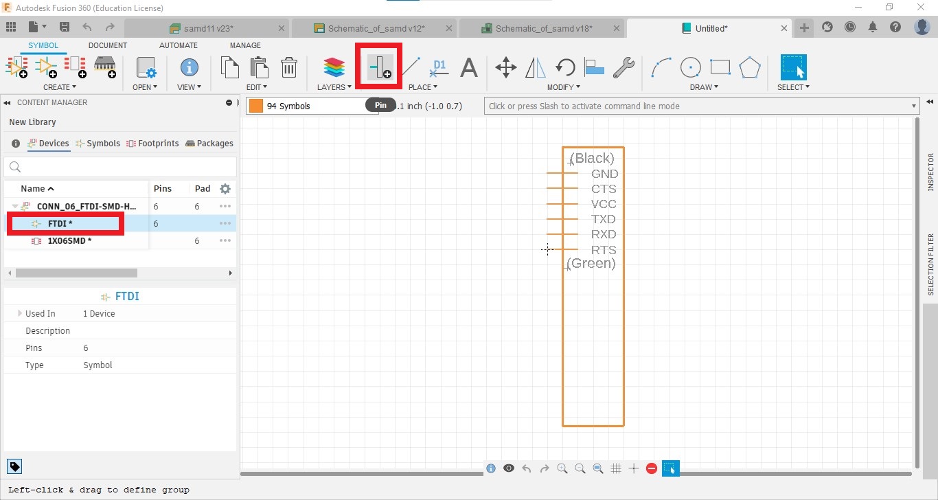
I designed the device by editing the CONN_06_FTDI-SMD-HEADER which included in fab library.
How?
- Go to File → New electronics library
- Go to Create → Create New Device and Click on import button and select the CONN_06_FTDI-SMD-HEADER from the fab library
-
Select the schematic symbol and increase the size of the rectangle. By clicking on the pin icon, we can add more pins
-
Select the Footprint and edit the foot print.
-
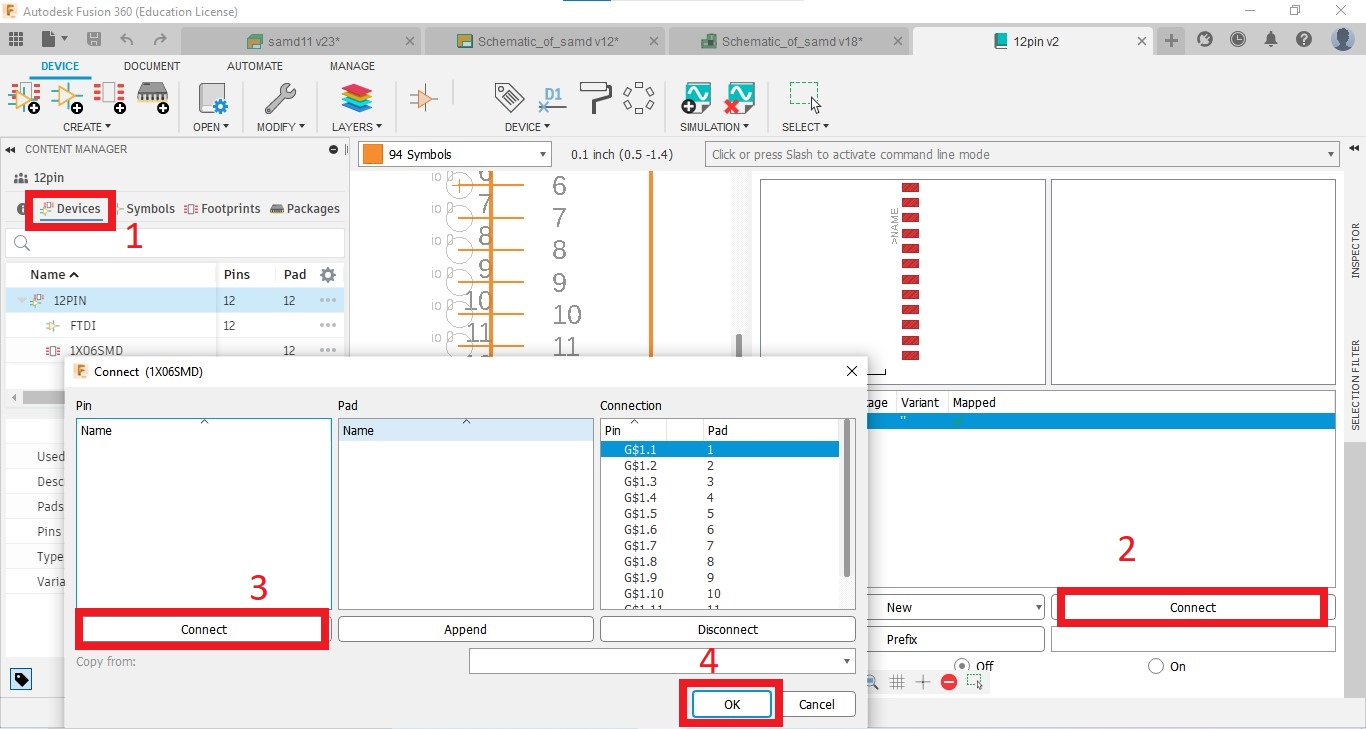
Go to Devices and click on Connect button. and connect pins of schematic and footprint.
-
Save the device
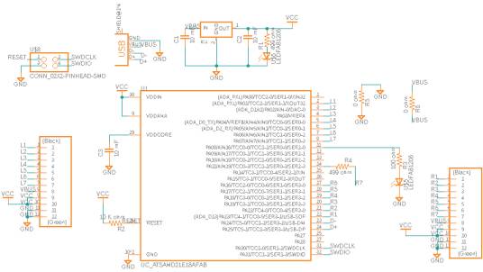
Schematic diagram.
Convert to PCB
I converted the schematic into PCB document and started to route. I tried for Autoroute. But I only got 50%.
Then I started to manually route traces.
It took more time to route.
While routing, there were some problems.
-
Air wire In my circuit, I couldn’t join some connections and showed them as air wires. So I added 2 zero Ohm resistors in the circuit.
- Add resisters in the schematic diagram and connect 2 sides of the resistor into common.
 -
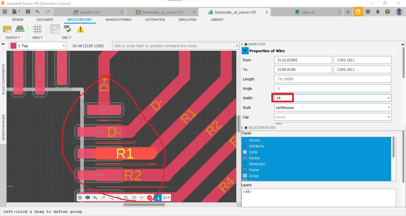
Clearance The clearance between pins of the Microcontroller was low and it showed as an error. So I decreased the width of traces. The steps are following below.
- Go to RULES DRC/ERC tab and → DRC and change the minimum width to 12 mil
- Select traces and decrease width from the INSPECTOR menu.
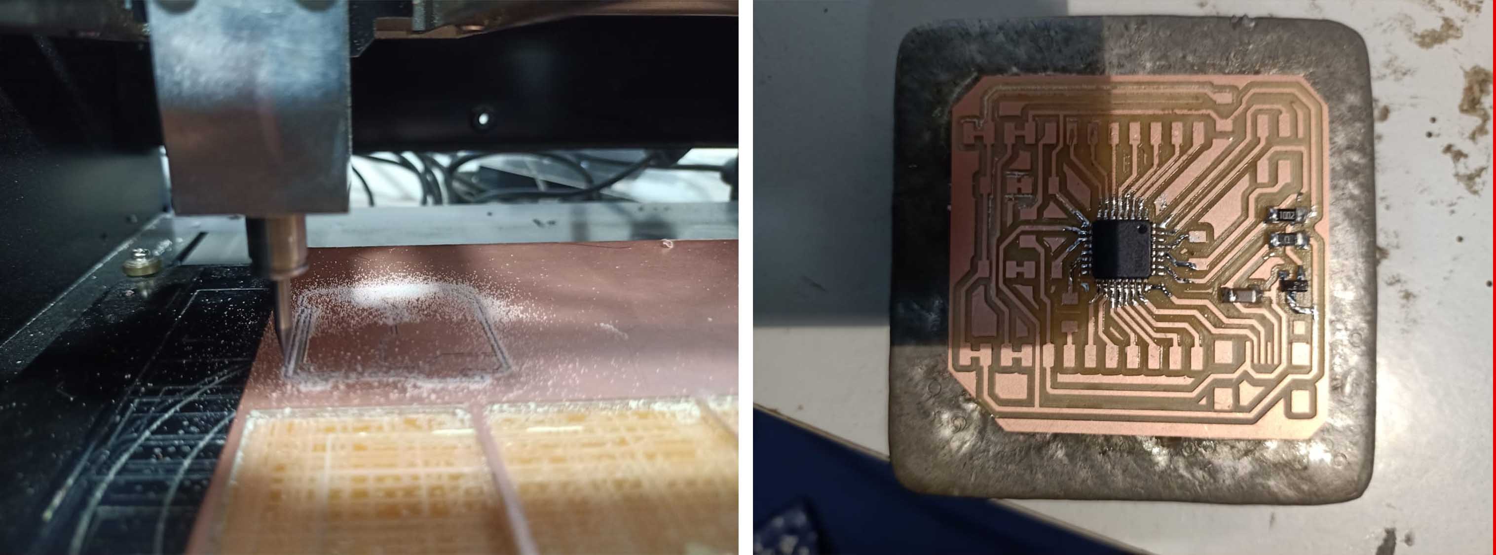
Milling and Soldering
Burning bootloader.
I used edbg for burning bootloader.
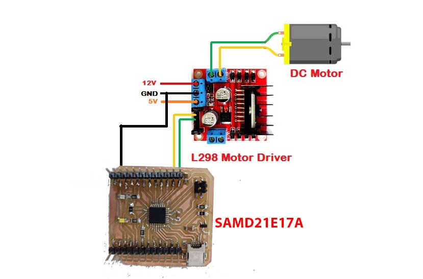
Control motor using SAMD21E17A and L298N motor controller
Before testing the stepper motor, I tested a dc motor using L298N motor controller.
Connection.
Programming
int motor1pin1 = 1;
int motor1pin2 = 2;

void setup() {
  // put your setup code here, to run once:
  pinMode(motor1pin1, OUTPUT);
  pinMode(motor1pin2, OUTPUT);
}

void loop() {
  // put your main code here, to run repeatedly:
  digitalWrite(motor1pin1, HIGH);
  digitalWrite(motor1pin2, HIGH);

  delay(1000);

  digitalWrite(motor1pin1, LOW);
  digitalWrite(motor1pin2, HIGH);

  delay(1000);
}
Finally successfully worked
Stepper motor
DRV8825 Stepper Motor Driver Module
The DRV8825 is a complete Micro-stepping Motor Driver with a built-in translator for easy operation. The breakout board from Texas Instruments features adjustable current limiting, over-current and over-temperature protection, and six different microstep resolutions. It operates from 8.2 V to 45 V and can deliver up to approximately 1.5 A Current per phase without a heat sink or forced airflow. It is rated for 2.2 A Current per coil with sufficient additional cooling.
Features
- Max. Operating Voltage: 45V
- Min. Operating Voltage: 8.2V
- Max. Current Per Phase: 2.5A
- Microstep resolution: Full step, 1/2 step, 1/4 step, 1/8 step, 1/16 step 1/32 step
- Over temperature shutdown circuit
- Under-voltage lock out
- Over current shutdown
- Dimensions: 20.5 x 15.5 mm (0.8″ × 0.6″)
- Short-to-ground and shorted-load protection
- Low RDS(ON) outputs
DRV8825 Motor Driver Pinout
The DRV8825 driver has total of 16 pins which are as follows:
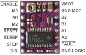
ref: how2electronics.com
I fixed motor driver on a bread board and give connection as given below.
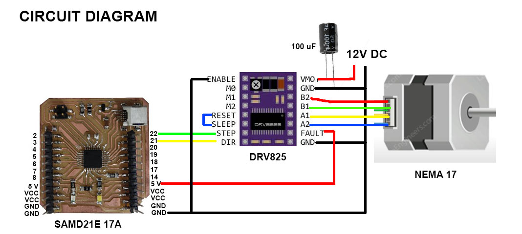
In the circuit.
- I connected STEP into 22th pin and DIRECTION into 21st pin.
- I shorted SLEEP and RESET together.
- I connected ENABLE pin to Ground.
- I give a 12 V DC supply with a capacitor of 100 microfarad.
Then I write a basic code with the help of internet.
#define dirPin 2
#define stepPin 1
#define stepsPerRevolution 200

void setup() {
  pinMode(stepPin, OUTPUT);
  pinMode(dirPin, OUTPUT);
  digitalWrite(dirPin, HIGH);
}

void loop() {
    digitalWrite(stepPin, HIGH);
    delayMicroseconds(2000);
    digitalWrite(stepPin, LOW);
    delayMicroseconds(2000);
  }
I take a little more time to operate the stepper motor with my board.
Finally successfully worked.
Bill of materials
| Part | Value | Device | Package | Description | MANUFACTURER | PACKAGE |
| C1 | 10mf | CAP_UNPOLARIZEDFAB | C1206FAB | |||
| JP1 | CONN_03X2-PINHEAD-SMD | 2X03SMD | PIN HEADER | |||
| R1 | 499 ohm | R1206FAB | R1206FAB | Resistor (US Symbol) | ||
| R2 | 499 ohm | R1206FAB | R1206FAB | Resistor (US Symbol) | ||
| R3 | 499 ohm | R1206FAB | R1206FAB | Resistor (US Symbol) | ||
| S1 | SW_SWITCH_TACTILE_6MM6MM_SWITCH | 6MM_SWITCH | OMRON SWITCH | |||
| U$1 | LEDFAB1206 | LEDFAB1206 | LED1206FAB | LED | ||
| U$2 | CONN_06_FTDI-SMD-HEADER | CONN_06_FTDI-SMD-HEADER | 1X06SMD | |||
| U$3 | LEDFAB1206 | LEDFAB1206 | LED1206FAB | LED | ||
| U1 | ATTINY412-SSFR | ATTINY412-SSFR | SOIC127P600X175-8N | None | Microchip Technology | SOIC127P600X175-8N |