8. Computer controlled machining
Task: Computer-Controlled Machining
- Group assignment:(Page Link is Here)
- Complete your lab’s safety training
- Test runout, alignment, speeds, feeds, and toolpaths for your machine
- Document your work to the group work page and reflect on your individual page what you learned
- Individual project
- Make (design+mill+assemble) something big In this week we are learning about Computer-controlled machining and CNC cutting.
SHOPBOT PRSalpha 96 CNC Router
It is the CNC machine we are using for woodworking.
To know about the machine I referred user manual and Assembly guide from internet
In Shopbot PRSalpha 96 CNC Router:
- Bed is not moving
- Spindle is moving X, Y and Z directions.
- The machine is controlled by a computer.
- It can use for carving, cutting and engraving.
Main parts of the machine:
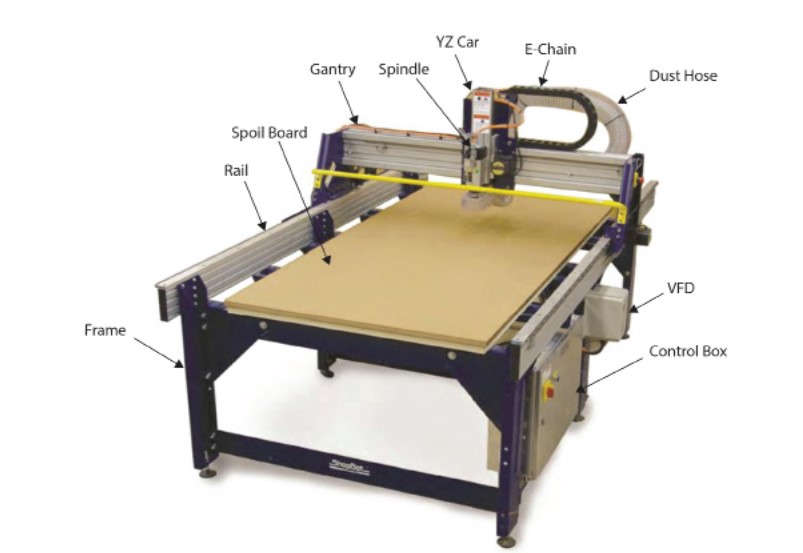
Control Box:
It contains a control board, motor drivers, and other electronic components. The PC is connected to the control box through a USB cable.
variable frequency device (VFD):
It controls speed and power for the spindle.
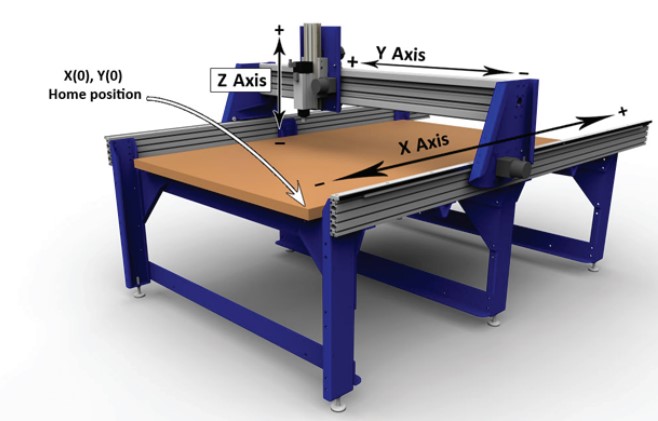
Axes:
The home position and axes of the machine are given in the figure below.
Spindle:
In SHOPBOT PRSalpha 96 CNC Router ,HSD FS915 5hp spindle is used.
General Safety and Precautions
-
Wear closed-toe shoes, safety goggles and ear plux.

-
Never place hands on the rails of the ShopBot.
- Never wear gloves while operating the machine
- Never leave a machine running and unattended
Creating a design.
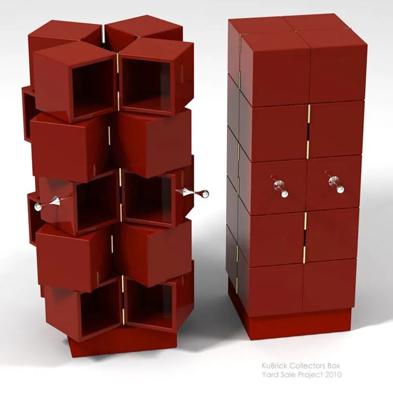
I had a plan to create something special this week. I saw a cabinet on YouTube. Its name is Cubrick Cabinet. It fascinated me. I tried to understand its mechanism. I didn’t get any clear idea from the internet. So I decided to find it’s mechanism. I made some base model using cardboard. and studied movements. Then I designed the model in Fusion360. The coinciding hinges was a big problem. I solved that problem by lifting the position of one hinge.
But I was not confident with using wooden hinges and wooden bearings.
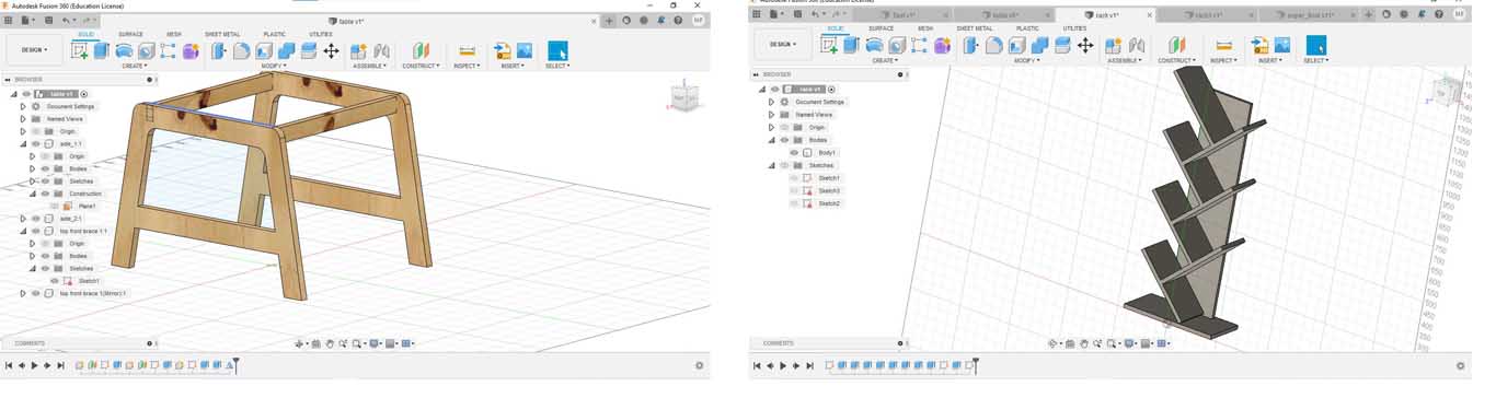
So I designed a table and a book rack in fusion360. I lasercut the design by changing parametric values.
Our shopbot machine had a complaint, After repairing that, I didn’t get time to cut my design.
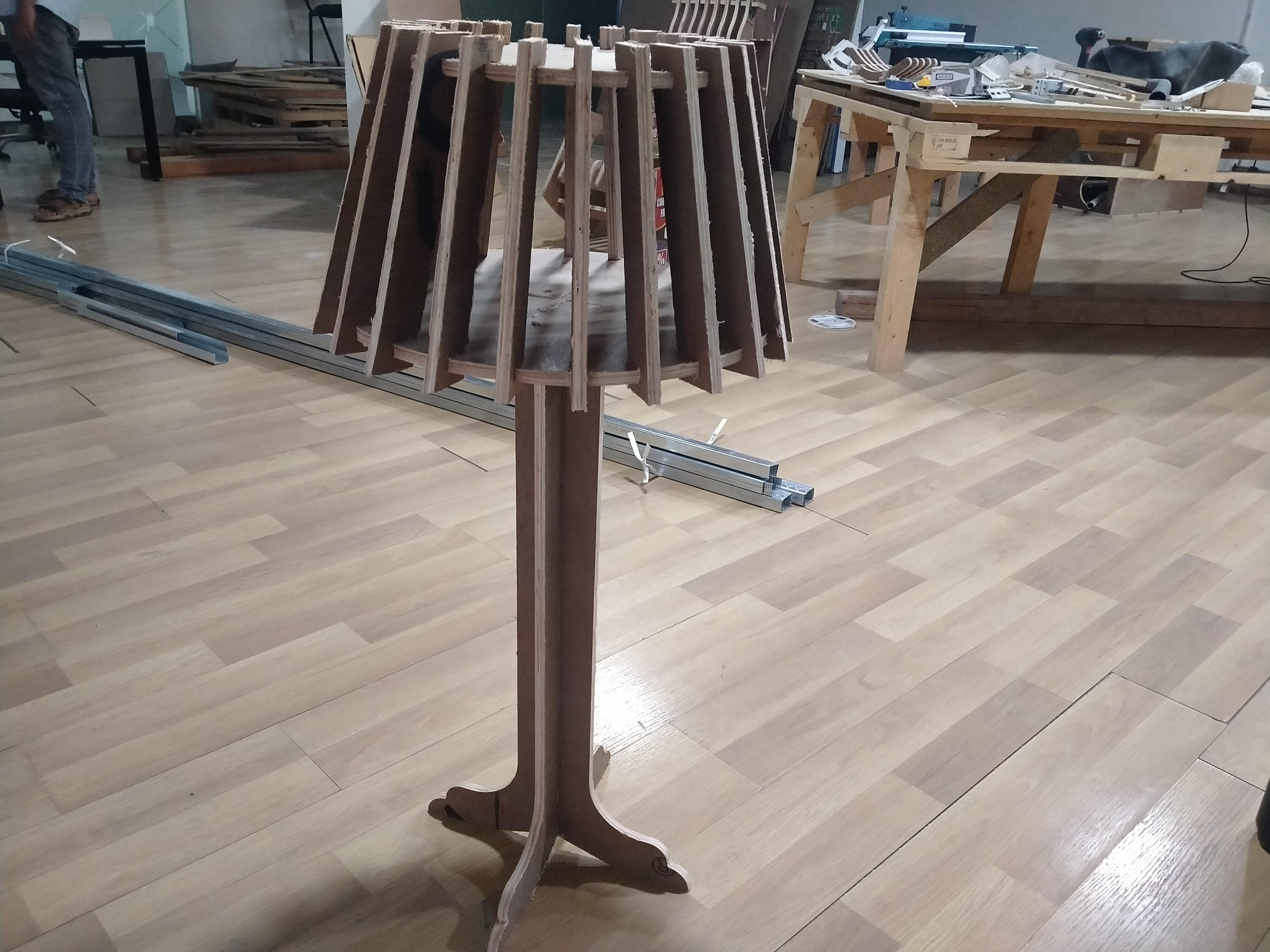
Creating a new design
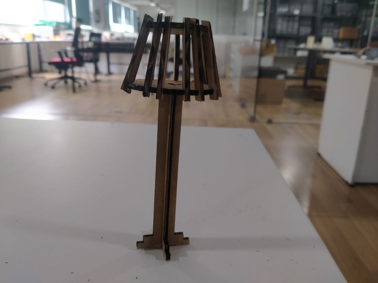
After the Computer controlled week, I thought about making cubrick cabinet again. I spend a lot of time to understand what is the mechanism behind that. However I got the idea of the mechanism after a long time. But the mechanism includes Pinslots, bearings and hinges. So I decided to make a floor lamp to complete the week assignment.
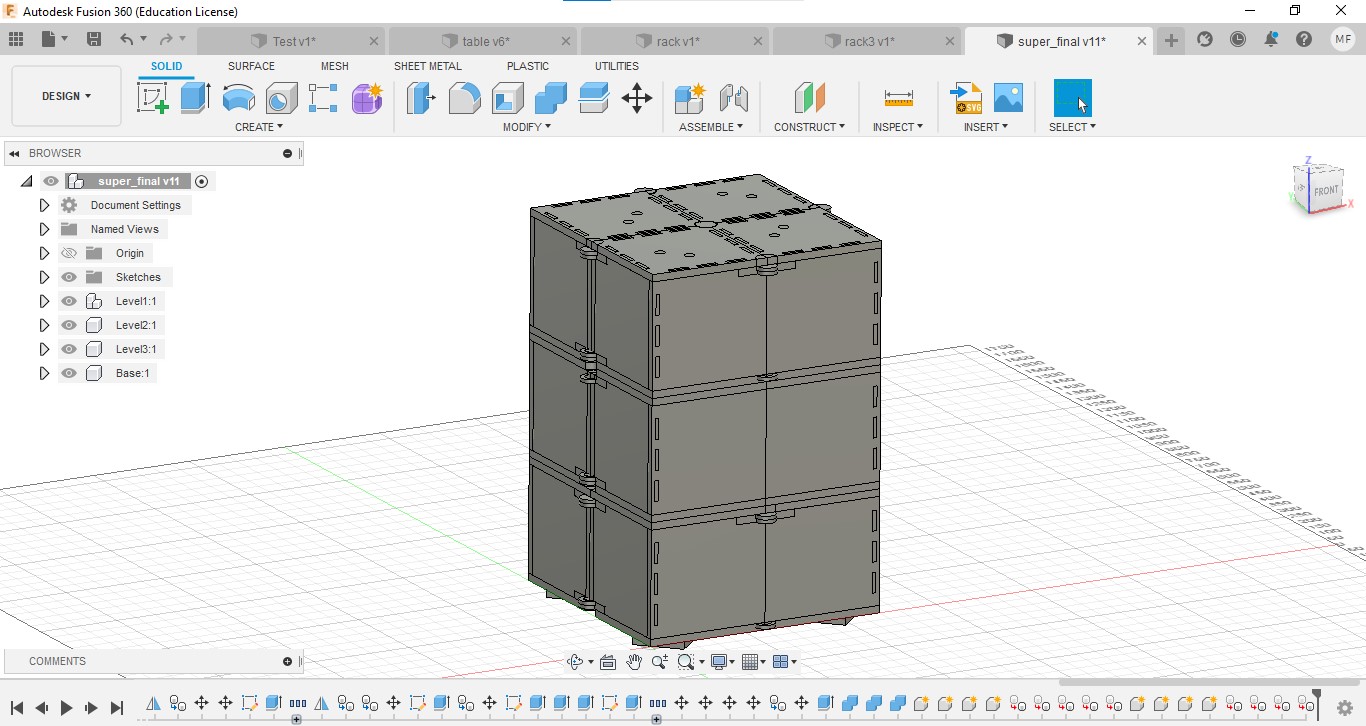
I designed it in the FUSION 360 with parametric design.
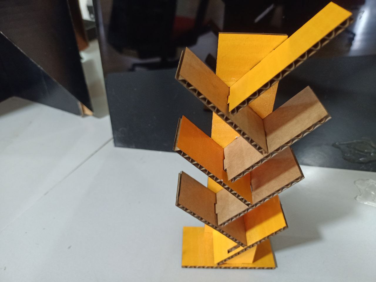
After designing the model, I made a miniature with cardboard using laser cutter.
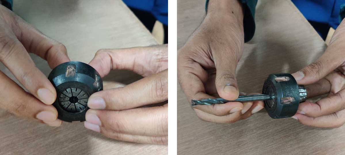
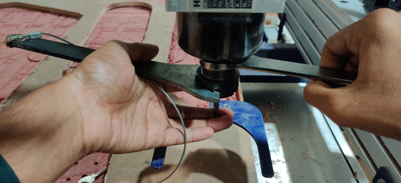
Bit changing in Shopbot
- Remove and take the key attached to the collet wrench
-
Lose the locknut using a collet wrench and spanner
-
Collect bit, collet, and locknut in hand.
- clean collet and locknut.
-
Press collet into locknut and place the bit inside.
-
Insert these into the spindle and tighten the locknut. Support bit with finger.
Making G-code in V-Carve pro
- Open V-Carve pro, go to File → Open→ and select the Dxf file of our design.
-
Go to Edit→ Job size, Then set dimensions of the material. and set origin point.
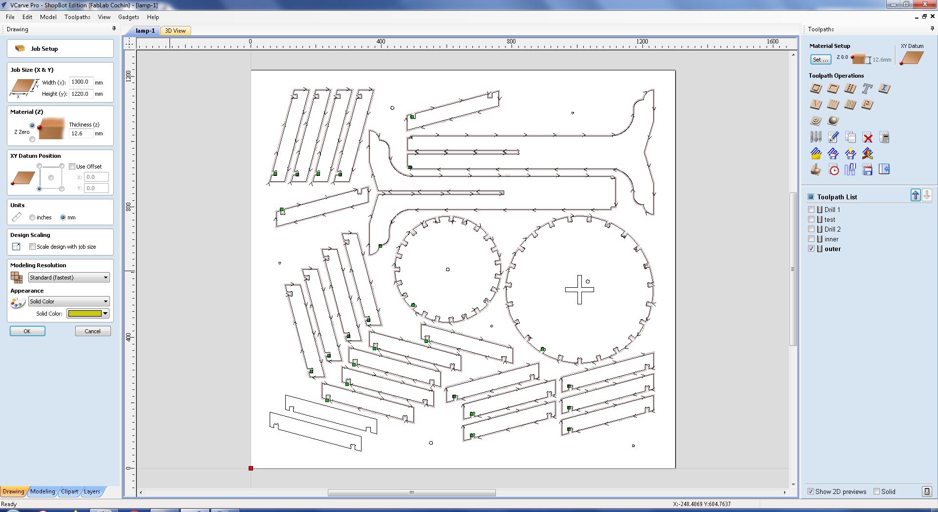
-
After that I measured space between 2 components and I checked with the plywood size on the bed.
-
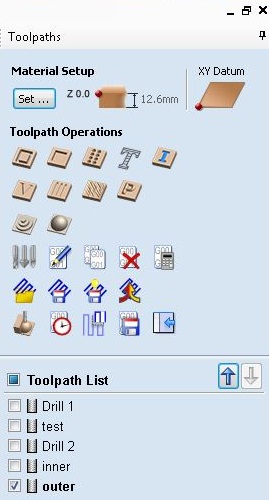
Tool path window is on the right side, I created different tool paths for drilling, Inner cutting and outer cutting. To create a tool path:
- Select shapes and select a toolpath operation.
- In the opening small window, we can edit properties(select tool, toolpath direction, tab etc,…) I used 6mm 2 flute bit for all operations.
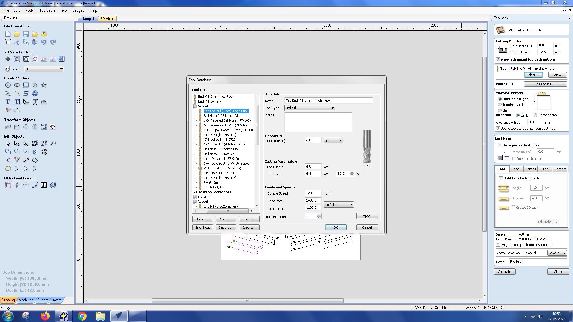
- After setting all, click on the calculate button.
- After creating different tool paths select some toolpaths and click on save button.
Operating Shopbot
After saving the G-code in the V-carve software, I operated the Shopbot machine. Our Instructor Joel Alex guided me to operate the machine. Steps I followed are given below.
- Power on Shopbot machine and Vacuum.
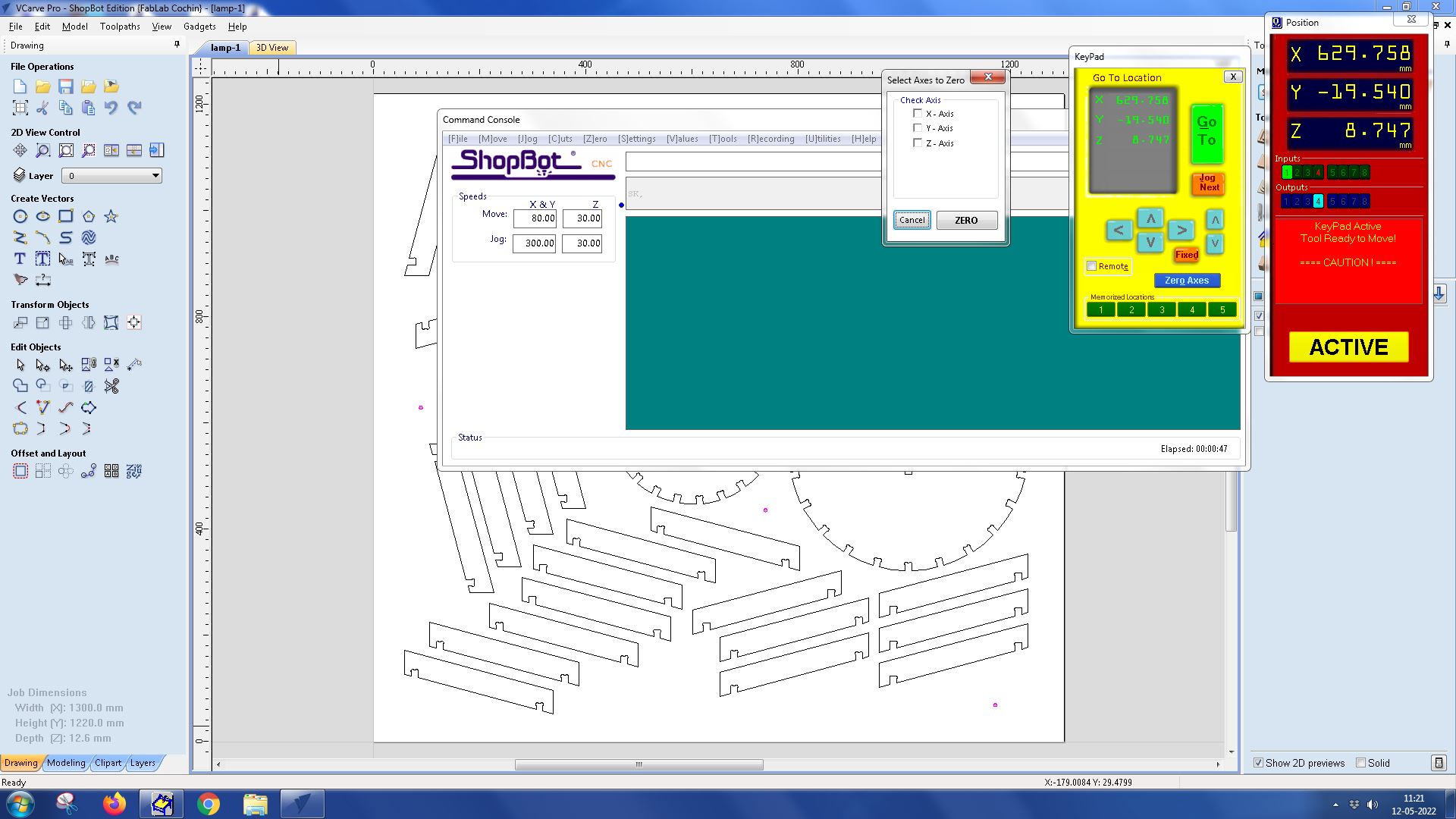
- Open Shopbot control software. In the Shopbot control panel click the yellow button to bring up the jogging panel. We can move each of the three axes using the arrow buttons.
-
After setting the Origin point of the tool using navigation keys, click on the Zero axes button and tick on Zero Axes button to set that point as Origin point.
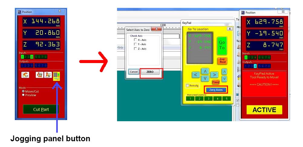
-
Close the Jogging panel and click on CUT PATH button → Select the G-code file for cutting.
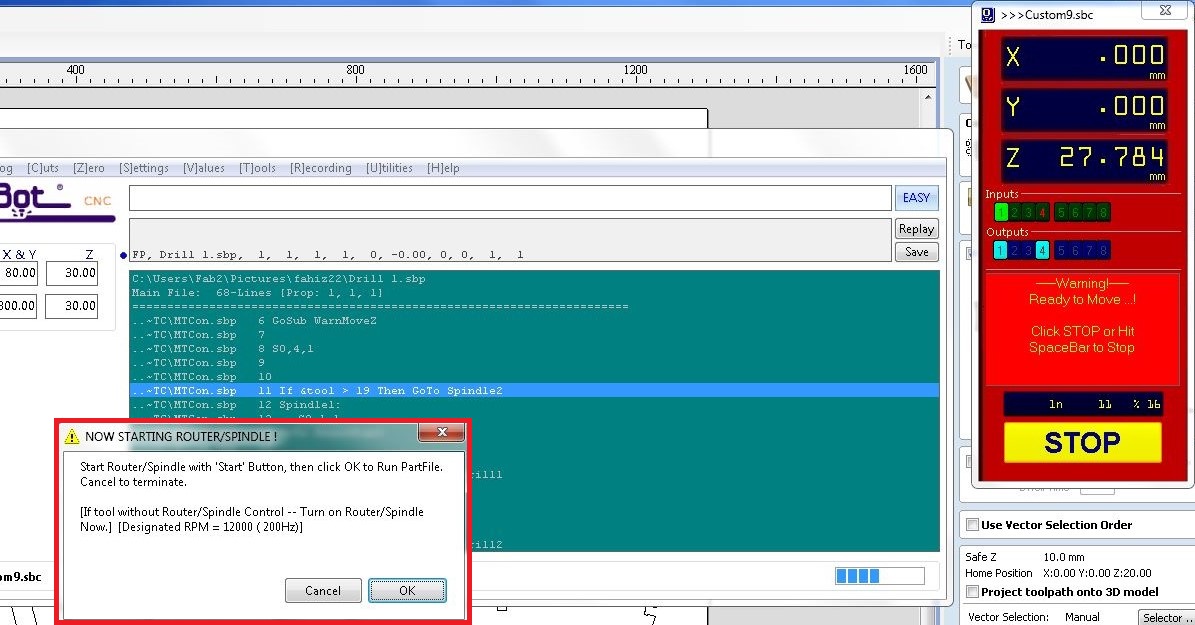
- Then an alert window will appear. At that time press switch for spindle on.
-
After conforming the spindle is rotating, click on OK button to run the G-code.
-
Open ShopB
- ot software. User interface is very simple.
- After Turn on Shopbot machine, Click on Move button, We can use jog.
- Click on Zero axes button, and tick on X-axis, Y-axis, Z-axis and click on ZERO button.
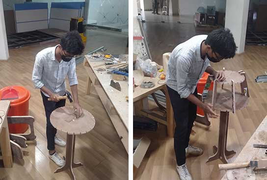
After milling.
-
My plywood sheet was a little uneven in thickness. So some portions didn’t cut well. Then I separated using a chisel.
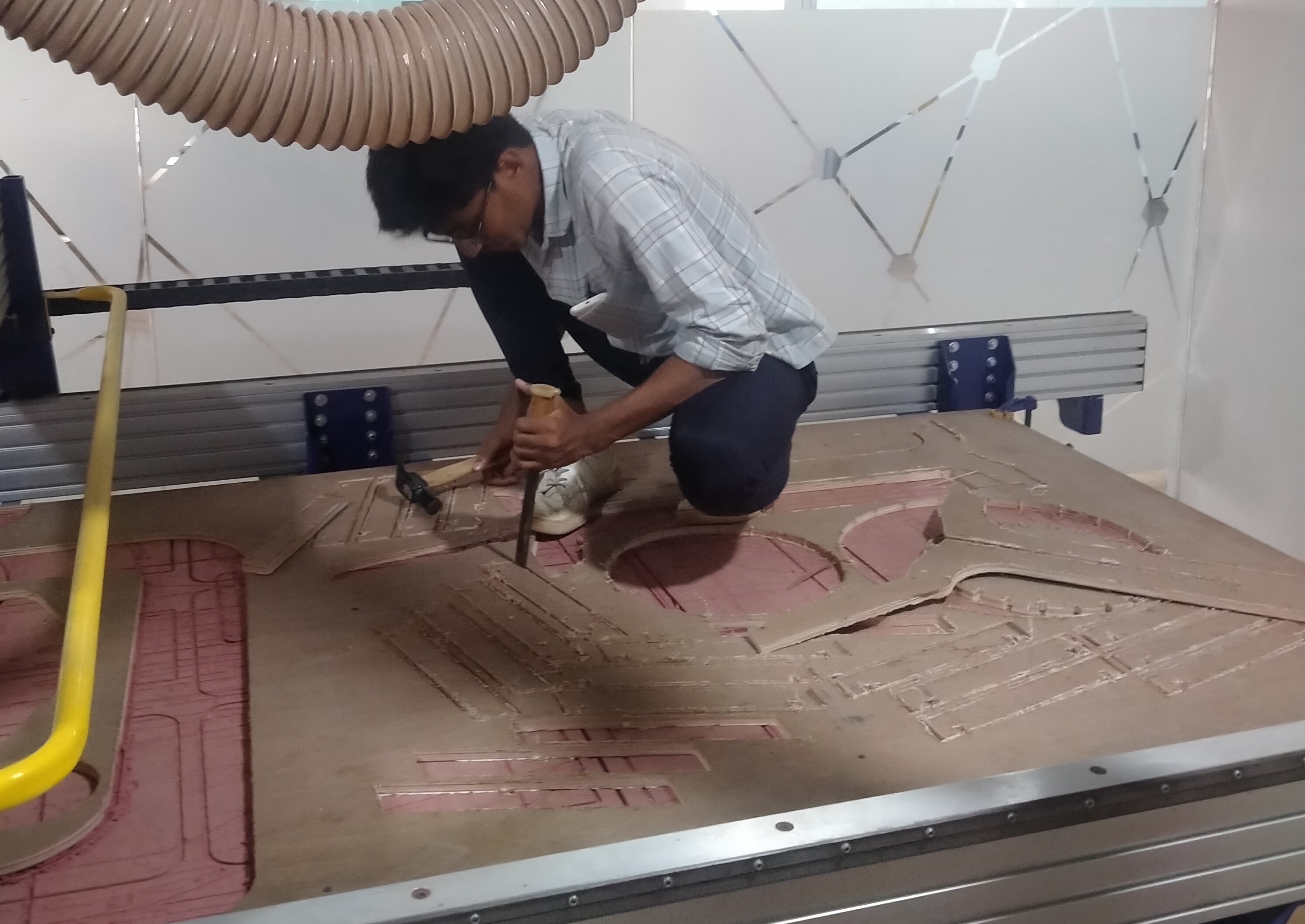
-
I sanded edges using a file and joined each part. Fitting was perfectly fit.