10. Molding and casting
Task: Moulding and Casting
- Group assignment:(Page Link is Here)
- Review the safety data sheets for each of your molding and casting materials
- Make and compare test casts with each of them
- Individual assignment:
- Design a 3D mould around the stock and tooling that you’ll be using, mill it (rough cut + (at least) three-axis finish cut), and use it to cast parts.
When I saw toys at street vendors at festivals, I often hoped I could make and sell some toys based on my ideas. Now is the time to learn the skills of molding and casting.
Molding: it is the act of creating the cavity/form that carries a negative or reverse impression of an original model. Molds can be made of a rigid material, such as plaster or plastic resin or more commonly, flexible material such as rubber. The material to use should be chosen considering the material of the model, the material to be used to make castings, and whether there are any undercuts.
Casting: It is the act of pouring liquid material into the cavity of a mold. After a period of time, this liquid will cure via chemical reaction or cooling. The solidified part is also known as a casting, which is ejected or broken out of the mold to complete the process. Casting materials are usually metals or various cold-setting materials that cure after mixing two or more components together; examples are epoxy, concrete, plaster, and clay.
ref: www.smooth-on.com
Casting Terminologies
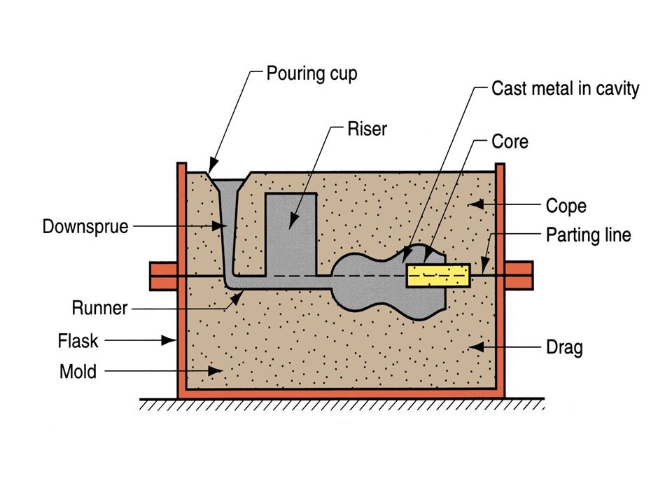
→ (1) FLASK:- The Flask is the box that contains the molding aggregate.
→ (2) Pattern:-It is the replica of the final object to be made with some modification.
→ (3) Parting Line:-This is dividing line b/w two parts of flask that makes the sand molds.
→ (4) Bottom board:- This is normally made of wood which is used to support the one end of the flask.
→ (5) Facing sand:- The Small amount of carbonaceous sand material sprincal on the internal mold surface of the cavity to give a better surface finish to the casting.
→ (6) Molding Sand:- It is Freshly Prepare refractory use for making the mold cavity.
→ (7) Backing Sand:- It is the bulk of the sand used to back up the facing sand & to fill up the volume of the flask.
→ (8) Pouring basin:- A Small Funnel Shaped Cavity at the top of mold into inch the molten metal is poured.
→ (9) Core:- A core is used in the Casting and molding Process to produce internal hollow cavities in the final product.
→ (10) Sprue:- It is a vertical-cavity in the molds to flow the molten metal from the pouring basin.
→ (11) Runner:- The pass-way in the parting line through which molten metal is regulated before they reach the mold cavity.
→ (12) Chills:- Chills are metallic objects which are placed in the mold to increase the cooling rate of the casting.
→ (13) Chaplet:- It is used to support the core inside the mold cavity.
→ (14) Riser:- It is a reservoir of molten metal provided in casting show that metal can flow back into the more cavity there is a reduction in the volume of metal due to solidifying.
Credit: bajrangengineering.in
Group assignment
Safety rules
- Make sure proper ventilation
- Wear gloves( For resin use nitrile gloves, and for metal-casting use heat-resistant gloves).
- Wear a Respirator or an N-95 mask.
- Wear safety goggles for eye protection
First Aid
Inhalation: Remove affected person from source of contamination. Move affected person to fresh air and keep warm and at rest in a position comfortable for breathing. Maintain an open airway. Loosen tight clothing such as collar, tie or belt. When breathing is difficult, properly trained personnel may assist affected person by administering oxygen. Place unconscious person on their side in the recovery position and ensure breathing can take place.
Ingestion: Rinse mouth thoroughly with water. Remove any dentures. Give a few small glasses of water or milk to drink. Stop if the affected person feels sick as vomiting may be dangerous. Do not induce vomiting unless under the direction of medical personnel. If vomiting occurs, the head should be kept low so that vomit does not enter the lungs. Never give anything by mouth to an unconscious person. Move affected person to fresh air and keep warm and at rest in a position comfortable for breathing. Place unconscious person on their side in the recovery position and ensure breathing can take place. Maintain an open airway. Loosen tight clothing such as collar, tie or belt.
Skin contact: Rinse with water and soap.
Eye contact: Rinse immediately with plenty of water. Remove any contact lenses and open eyelids wide apart. Continue to rinse for at least 10 minutes.
Protection of first aiders: First aid personnel should wear appropriate protective equipment during any rescue. Wash contaminated clothing thoroughly with water before removing it from the affected person, or wear gloves. It may be dangerous for first aid personnel to carry out mouth-to-mouth resuscitation.
ref: rs-online.com
Design a file
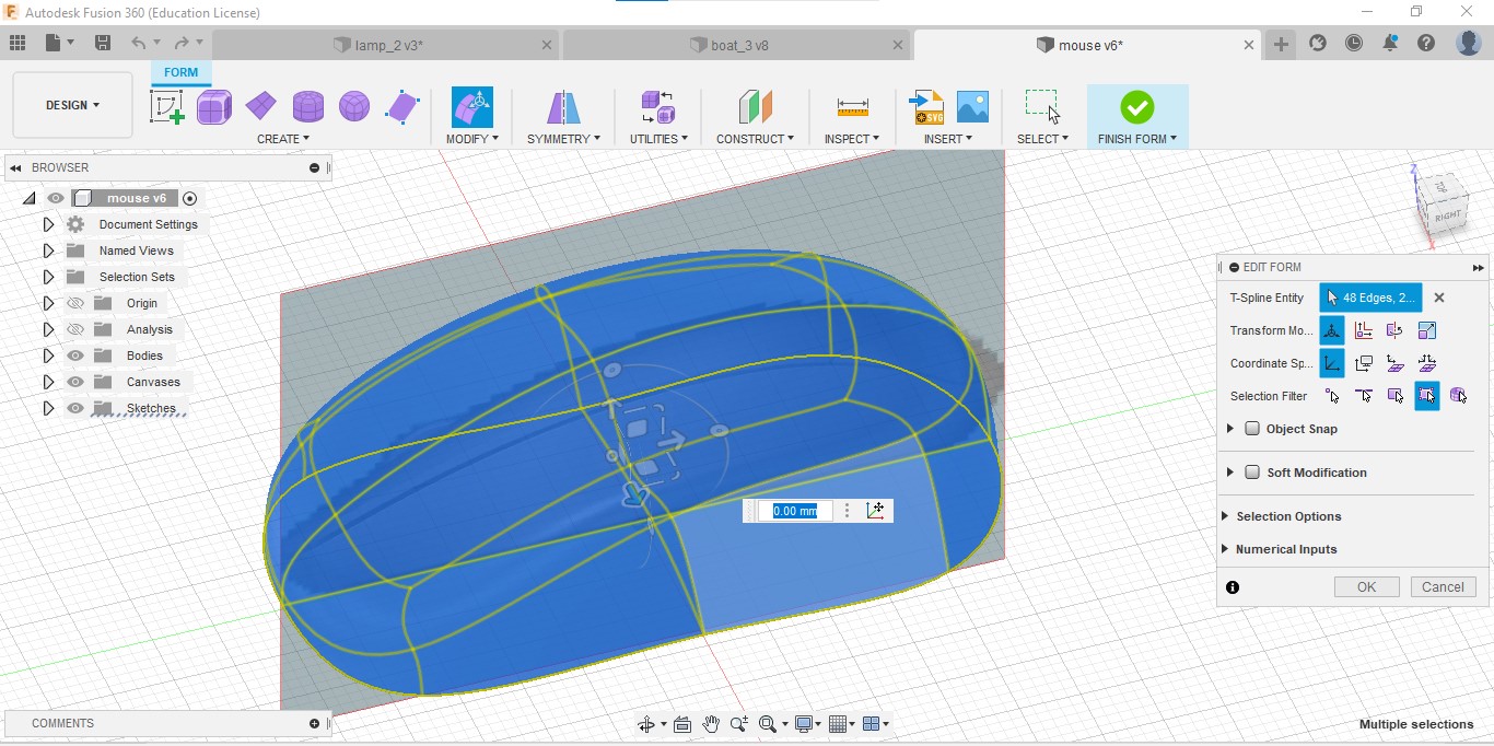
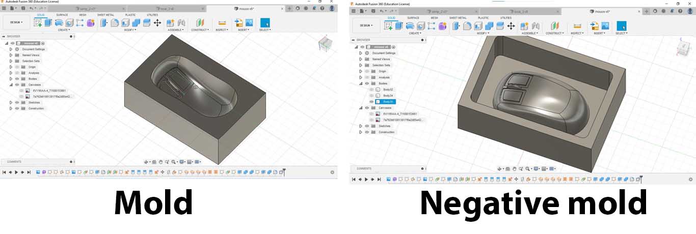
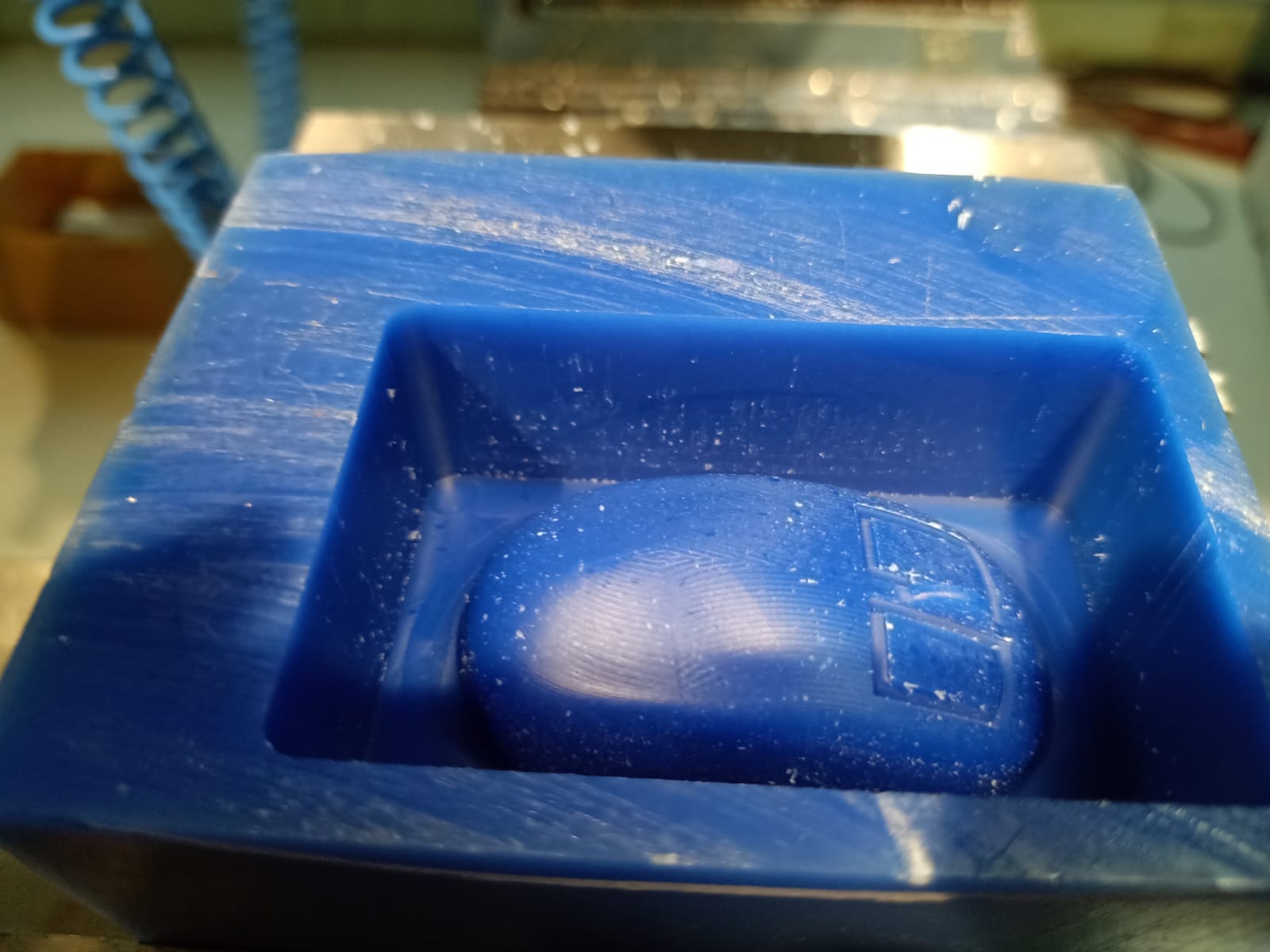
I designed a mouse in Fusion 360.
I used 2 canvases (the side view and the top view of a mouse).
and I designed using the Form feature.
I used sheet features to design the grooves of switch.
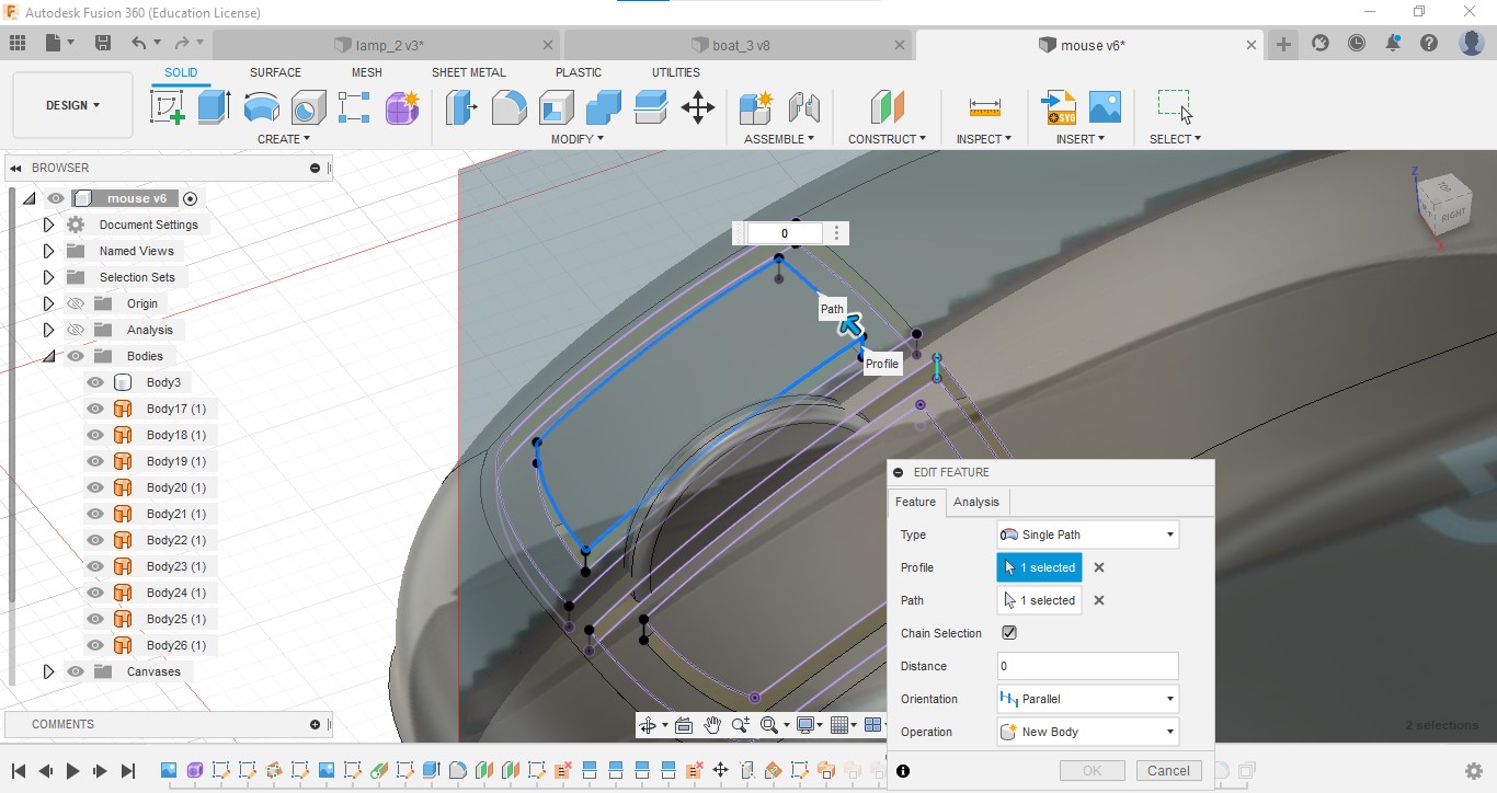
I made the mold and negative mold using the combine feature.
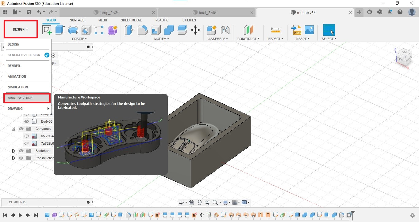
CAM designing
Go to Manufacturing Workspace. Then the manufacturing window will open.
Add tools
-
Go to MANAGE→ Tool Library
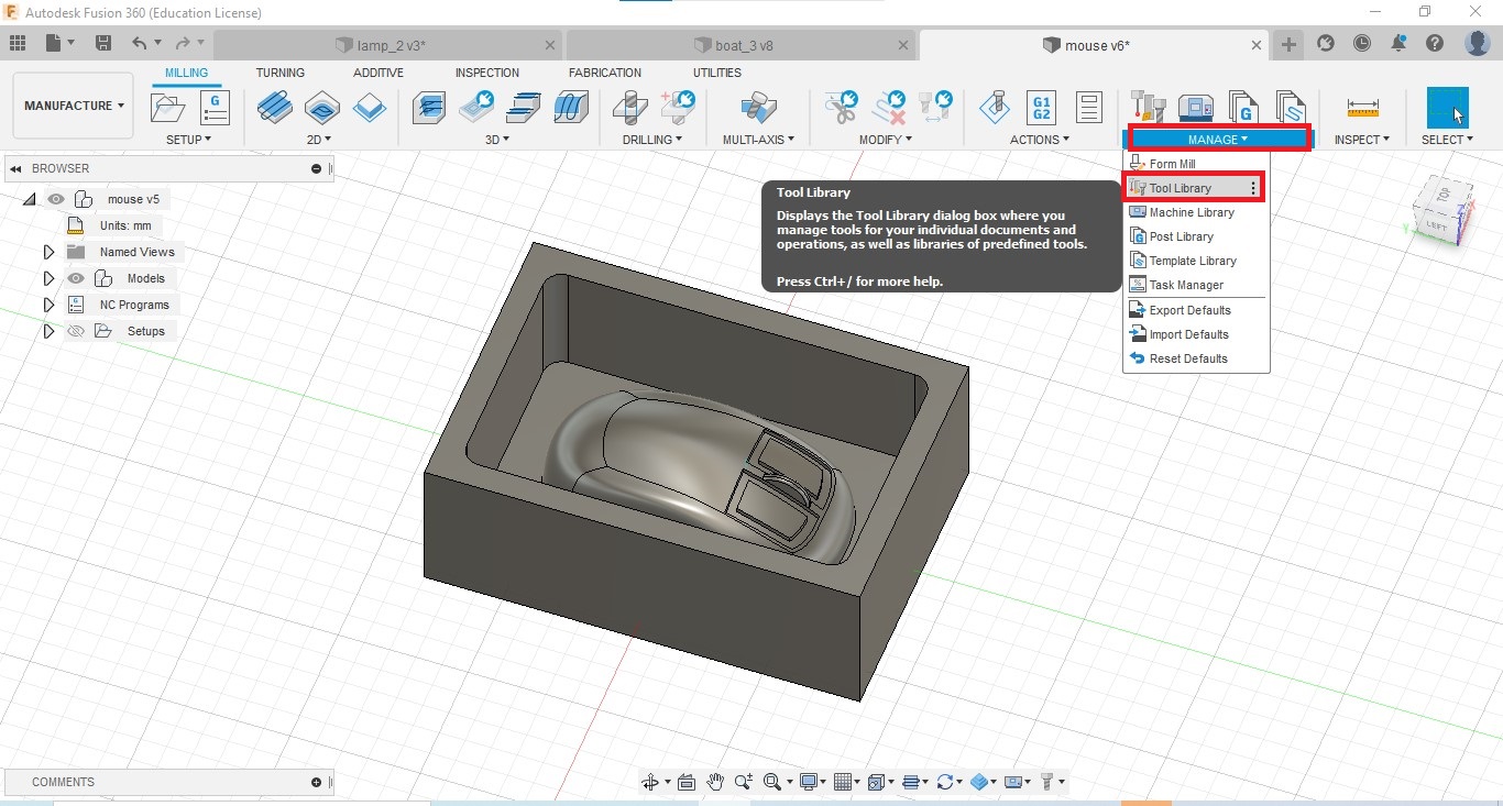
-
Select to Local → Library. By clicking on the plus icon, we can add tools.
-
From the opening window, select tool type(I selected the flat end mill)
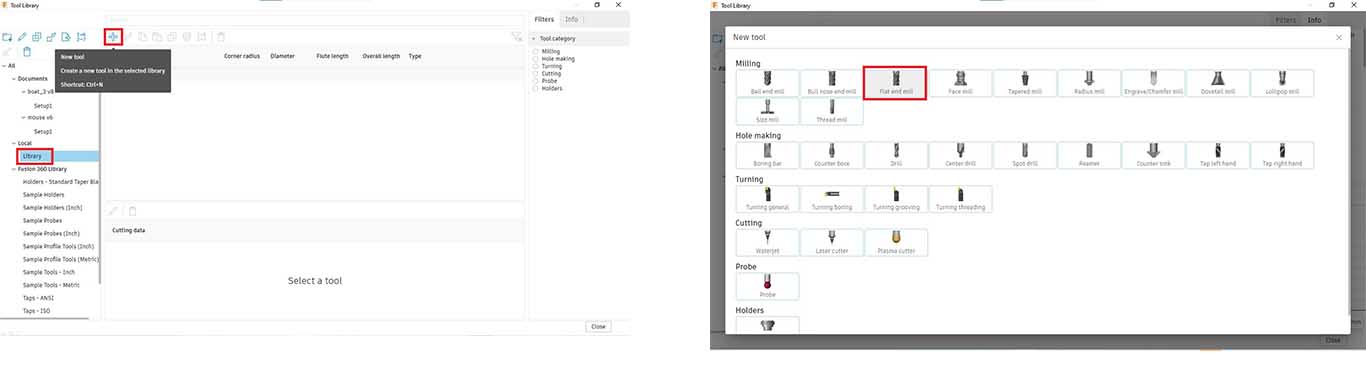
-
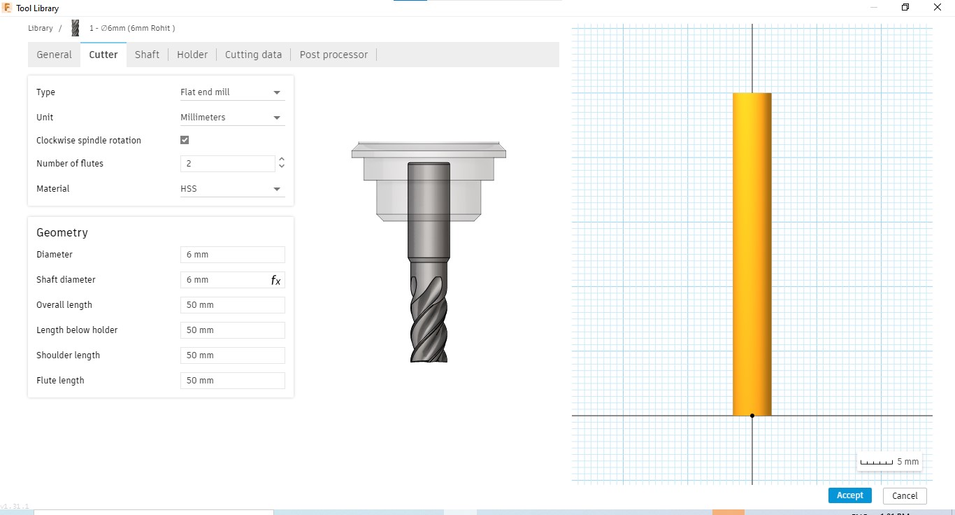
In the opening window, name the tool in the General tab. And go to the Cutter tab. and enter details.
Important tool settings of our 6 mm bit are:
Type: Face end mill
Diameter: 6 mm
Direction: clockwise
Number of flutes: 2
Material: HSS
Shaft Diameter: 6 mm
Overall length: 50 mm
-
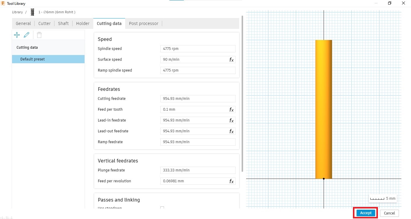
Go to the Cutting data tab. set speed and feed details. Cutting data for 6mm 2 flute flat endmill for wax are
Spindle speed: 4775 rpm
Surface speed: 90 m/min
Ramp spindle speed: 4775 rpm
Cutting feed rate: 954.93 mm/min
Feed per tooth: 0.1 mm
Plunge feed rate: 333.33 mm/min
After completing click on accept.
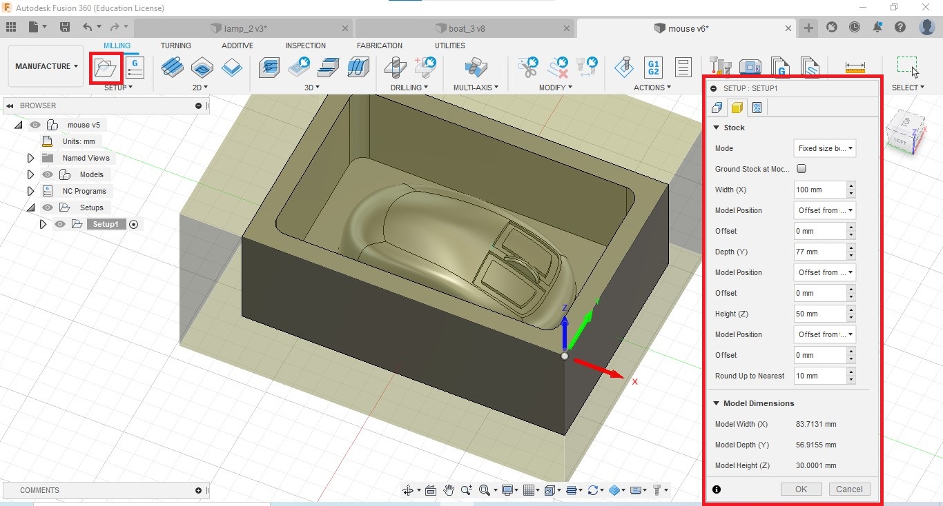
Setup
Click on the Setup button and setup the work coordinate system. and define the stock dimension
Add milling operations
I watched some videos and blogs about Fusion CAM operations. Blog by Autodesk is good for understand ( Link is here)
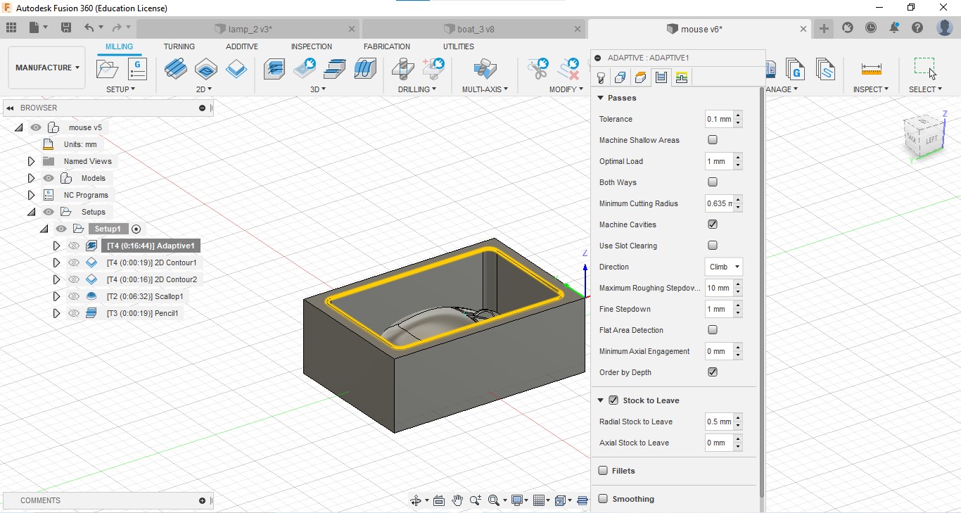
I used different milling operations for CAM, selected geometry for each operation is given below.
-
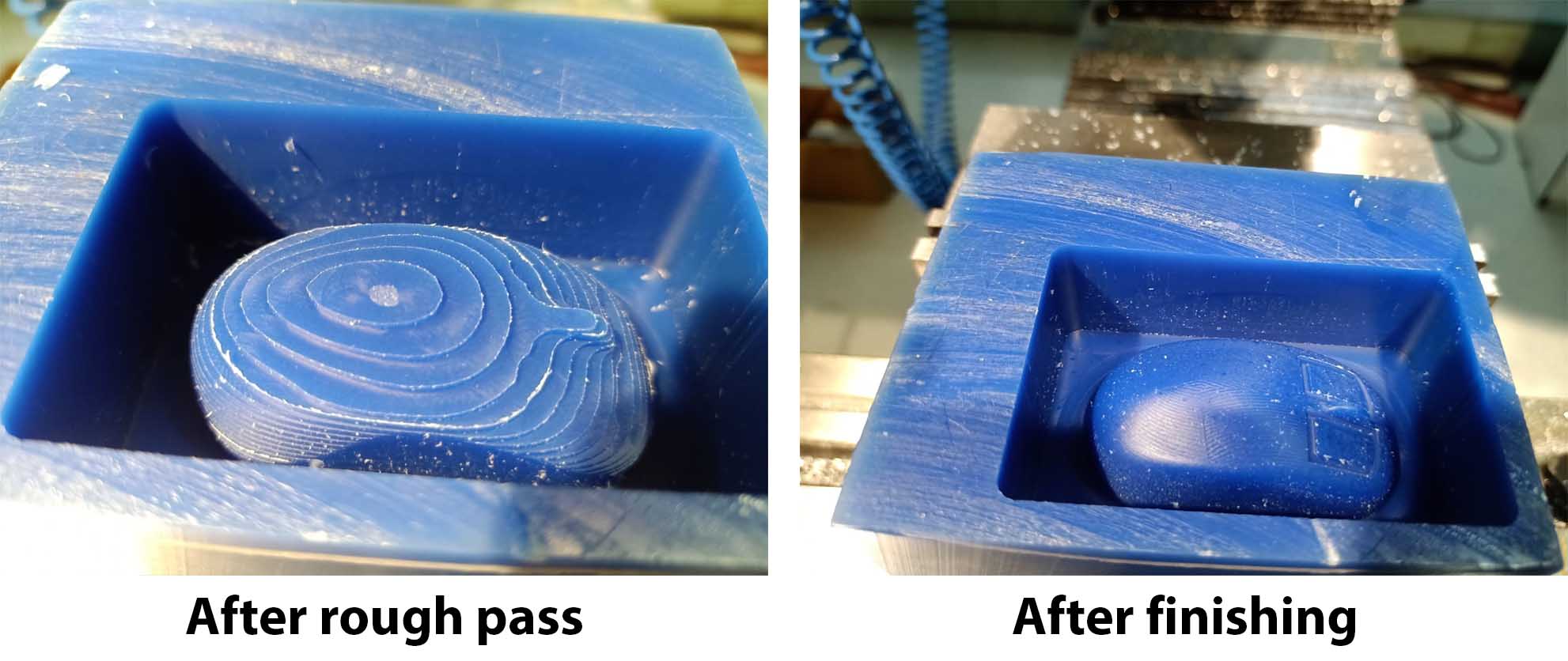
3D Adaptive clearing for Rough material removal
Tool: 6mm 2 flute flat end mill
-
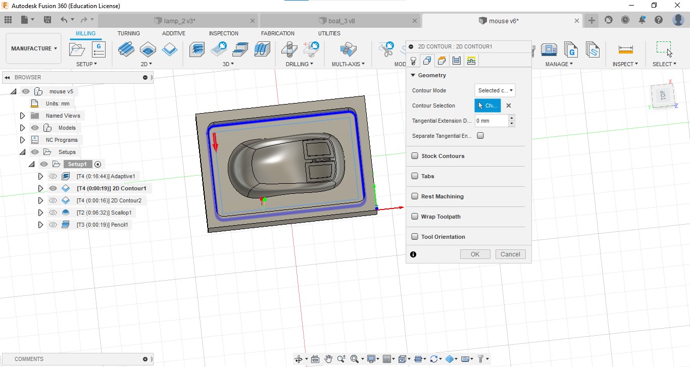
2D Contour for finish the inner wall of mold.
Tool:6mm 2 flute flat end mill
-
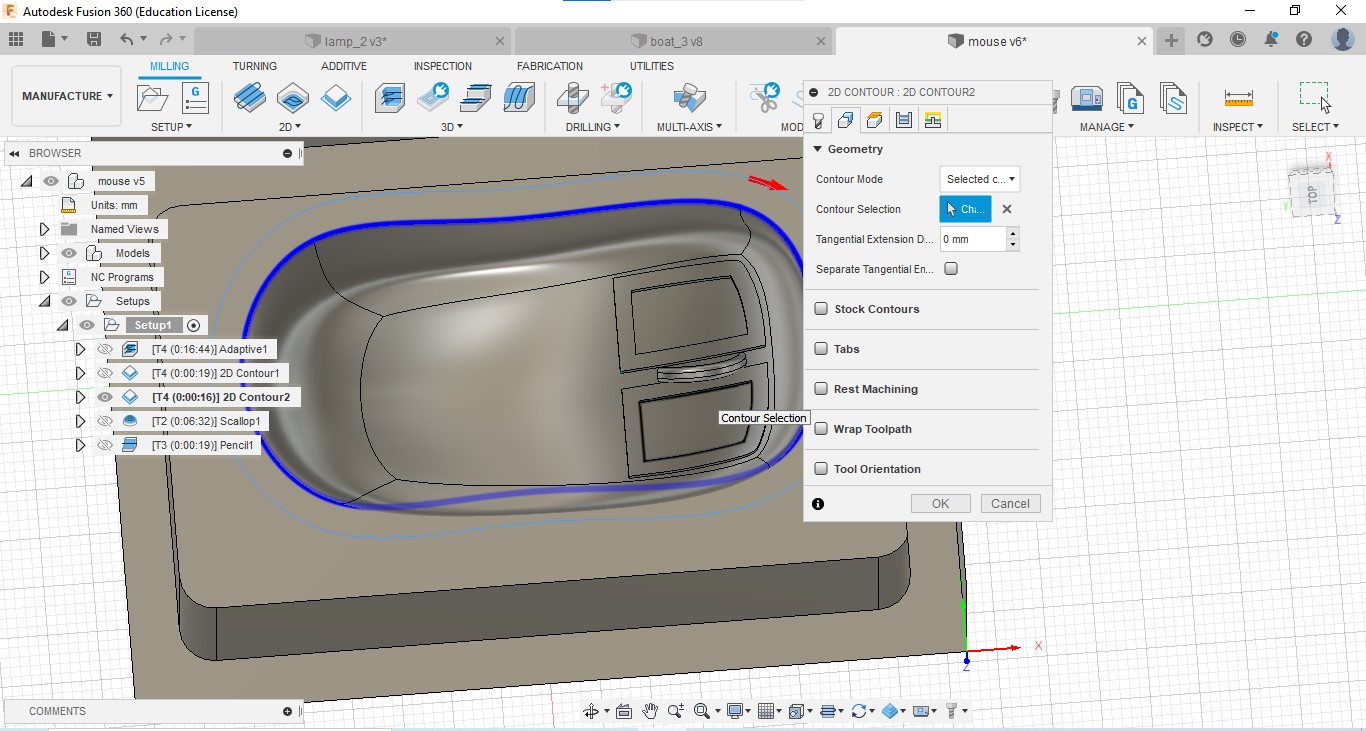
2D Contour for finishing the outside edges of the mouse design.
Tool: 6mm 2 flute flat end mill
-
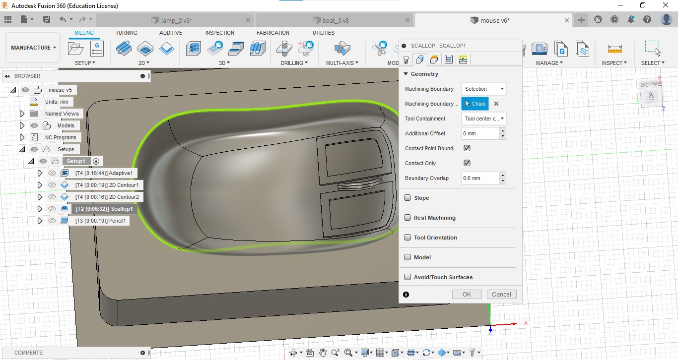
SCLLOP : For finishing the surface of the mouse.
Tool:6mm 2 flute ball end mill
-
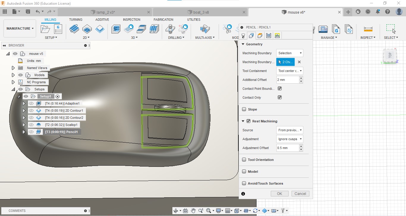
PENCIL: For the detailing of the grooves of the switches and scroller of the mouse.
Tool: 1/16 mil(1.5875 mm) 2 flute flat end mill
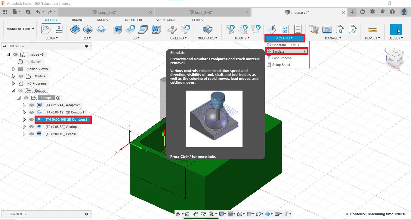
After each operation, I simulated and checked the operation time and problems, and edited those operations.
To simulate: Select the operation, Go to Actions → Simulate
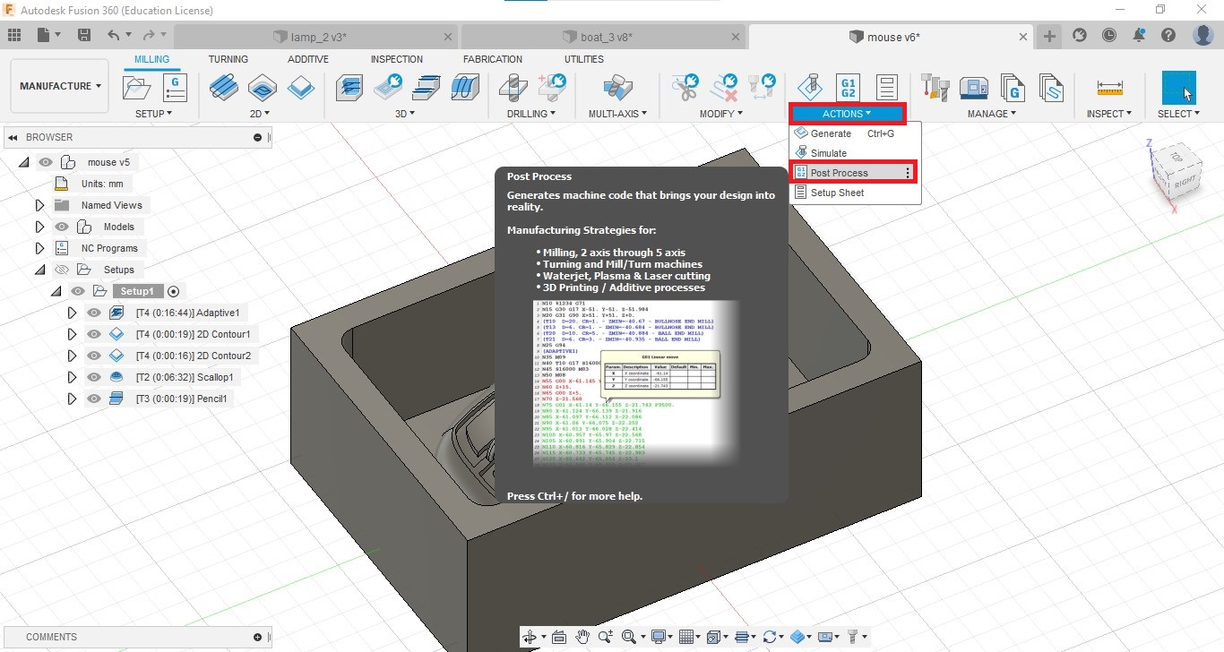
Generate GCODE
We have to generate GCODE and save the file.
Steps:
-
Go to Actions → Post Process
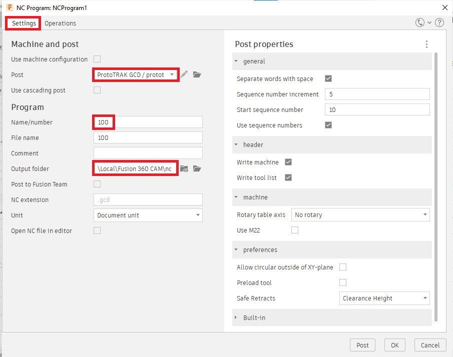
-
In the opening window, In the Settings tab, select machine in the Post column (We are using ProtoTRAK GCD) give a number as file name and select an output folder.
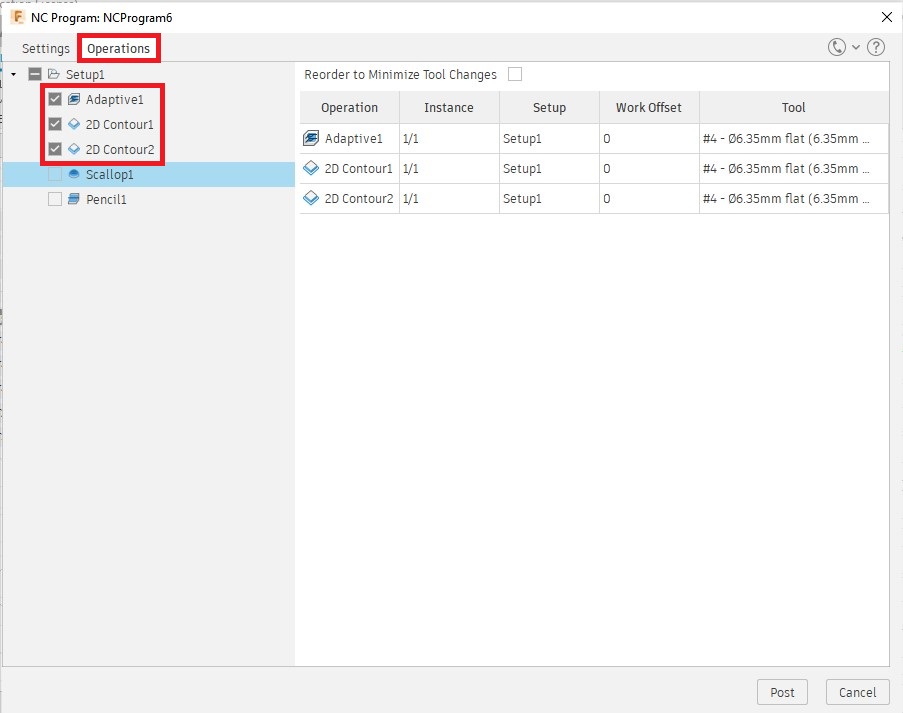
-
Go to Operations tab and select operations (I selected operations with same tool bits as a file)
Milling mold on Proto TRAK DPR X2
I milled my positive mold in ProtoTRAK. It was amazing.
Our mentors Rahul and Jogin explained the machine operation
The steps are given below.
- Turn on MCB and wait for the machine to booting
-
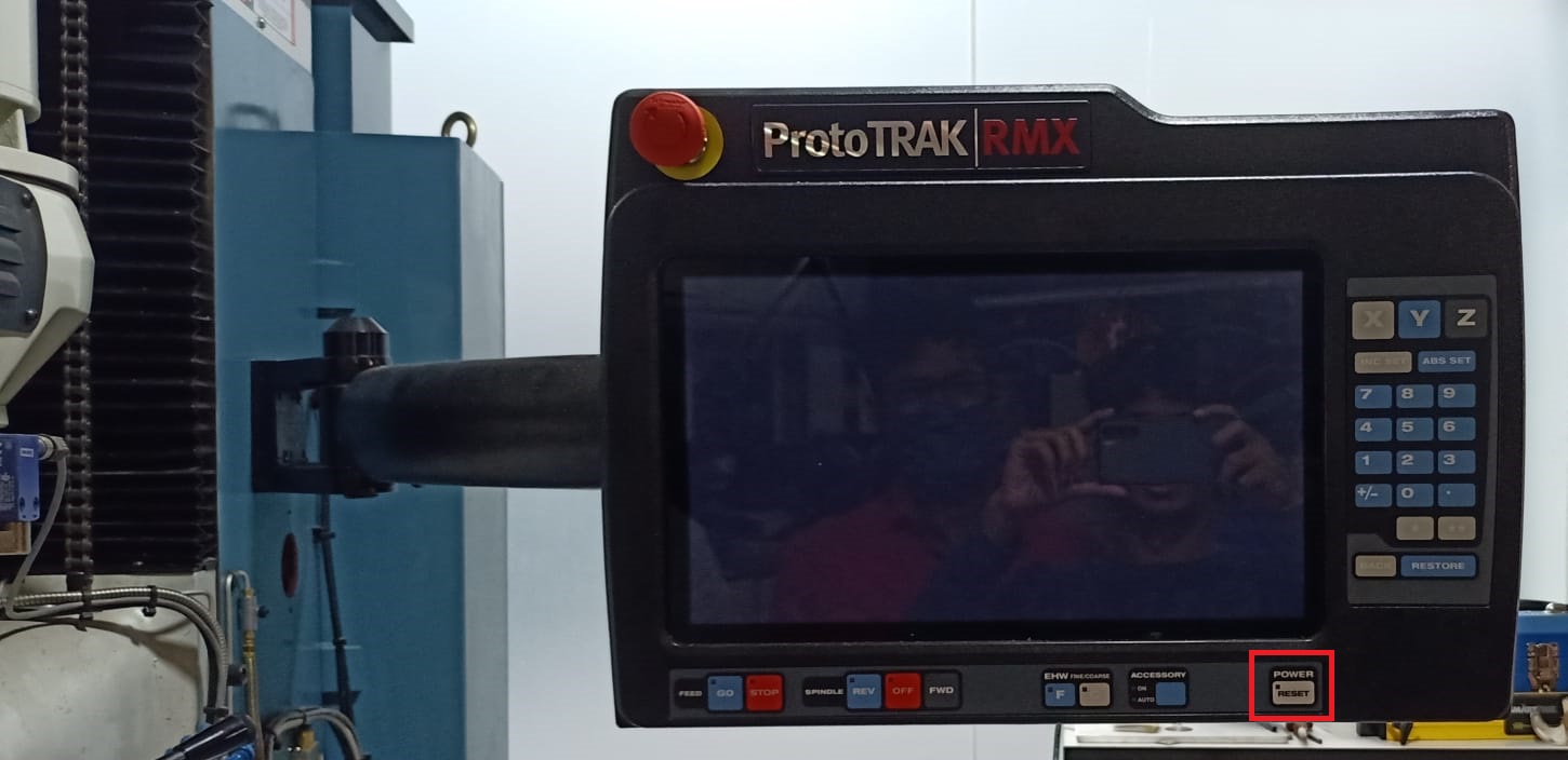
Long press the reset button on the DRO to enable the controller.
-
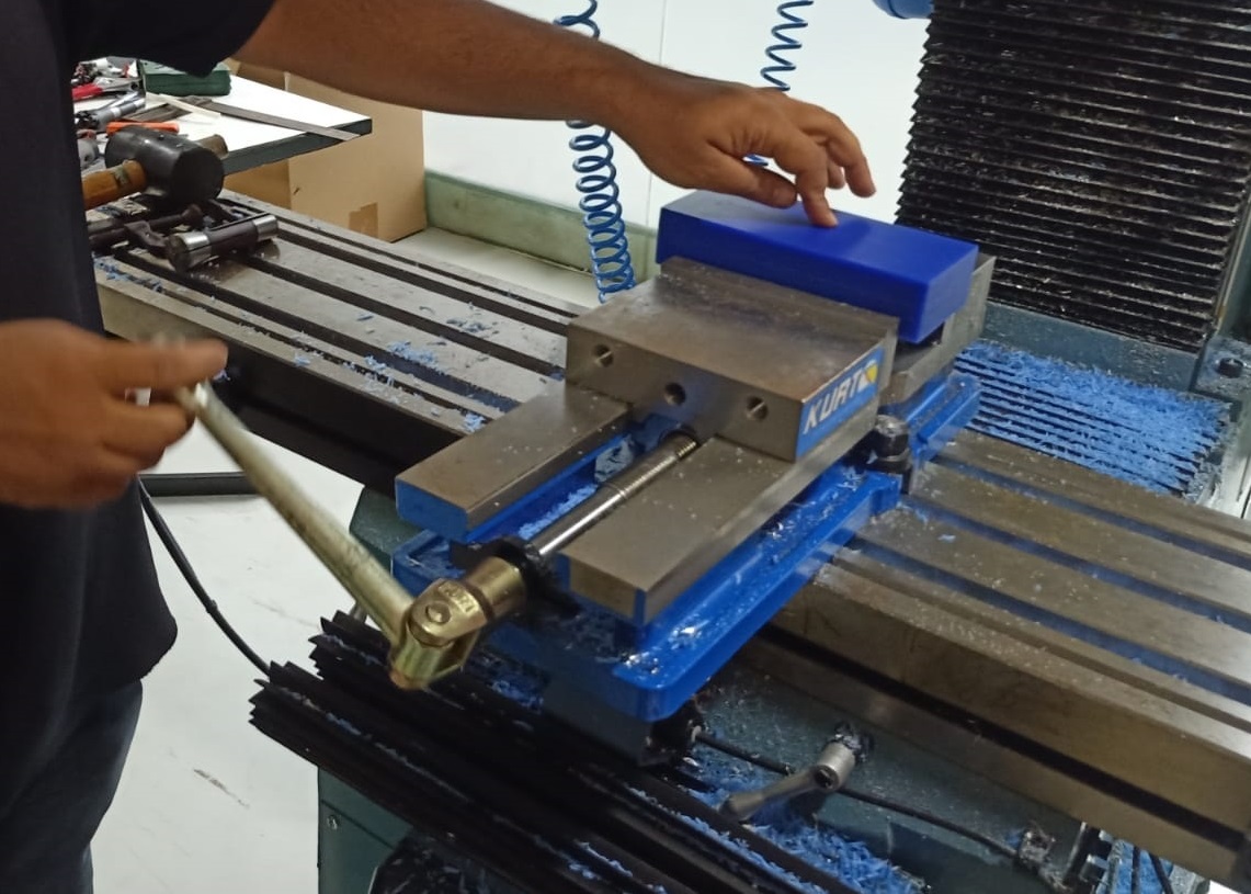
Place the wax block on the vise
-
Set X, Y origin at the corner of the wax block
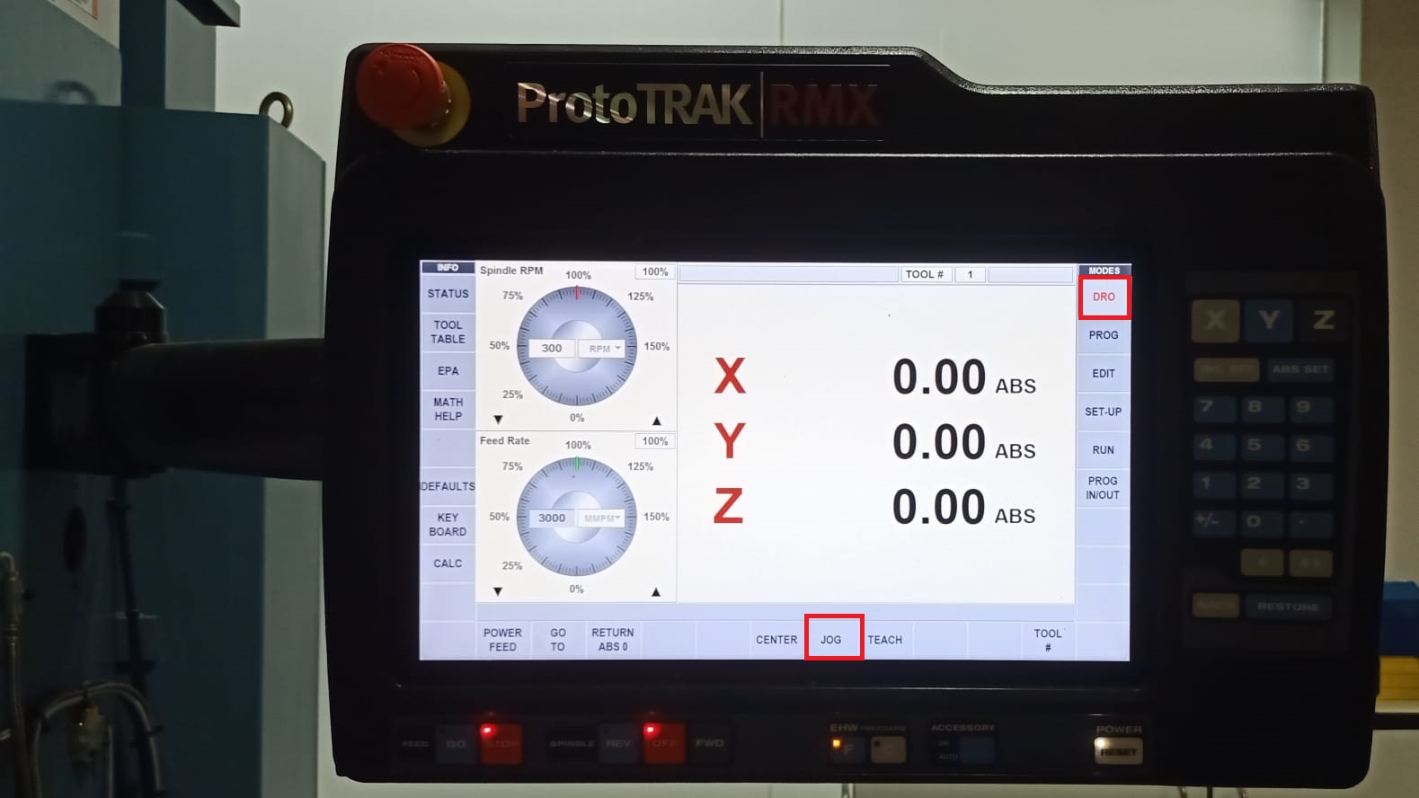
-
Go to DRO → JOG
-
Remove any tool in the spindle
- Insert edge finder in drill chuck and Insert the R8 drill chuck in the spindle
- Start spindle at 600 rpm
-
Zero X-axis
- approach the wax block from X+ to X- till the edge finder became concentric
- move the tool about 10 um in to the material and make sure the edge finder dislocates at the edge
- bring it 10um back to the original point
-
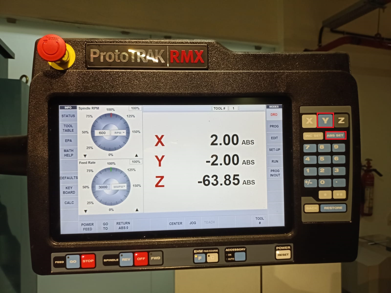
exit from JOG - press the X button and set the current position as 2[(edge finder dia)/2] and press the “set absolute” button
-
Zero Y-axis
- approach the wax block from Y- to Y+ till the edge finder became concentric
- move the tool about 10 um into the material and make sure the edge find dislocates at the edge
- bring it 10um back to the original point
-
exit from JOG - press the Y button and set the current position as -2 (edge finder dia/2) and press the “set absolute” button
-
-
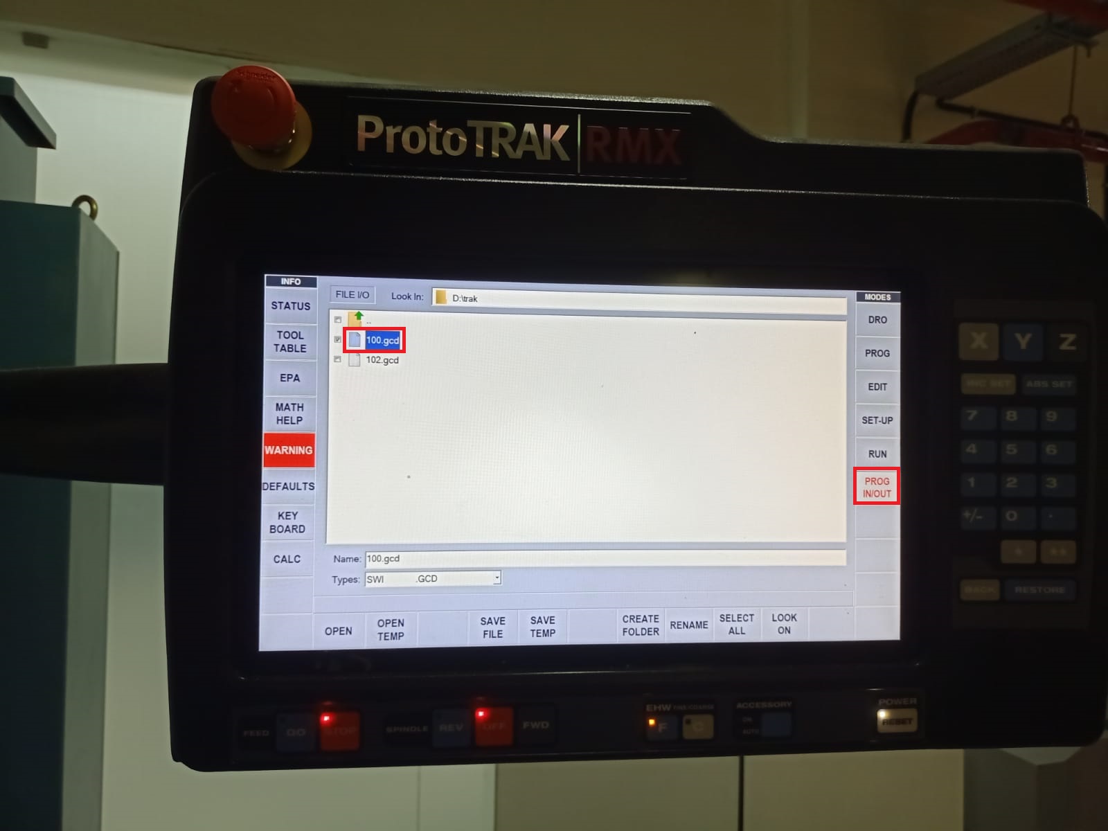
Press “program In/Out” → Select 1st GCODE file
-
Go to “Tool Table”
- Remove any tool holder/tool in the spindle → Press JOG and move the spindle close to the base point (Back of vise)
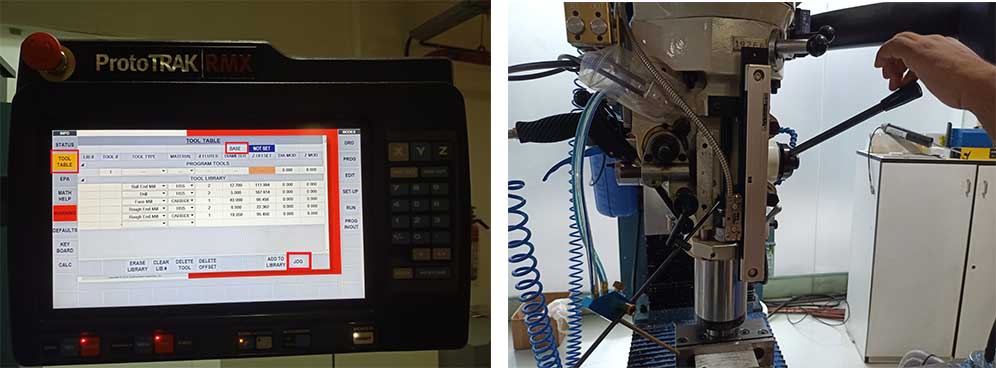
- Exit from JOG → Release the quill and press it against the base → Select base → Press “Set absolute ” to set the base point.
- select the tool for the operation → If not create a new one by specifying the type and diameter
-
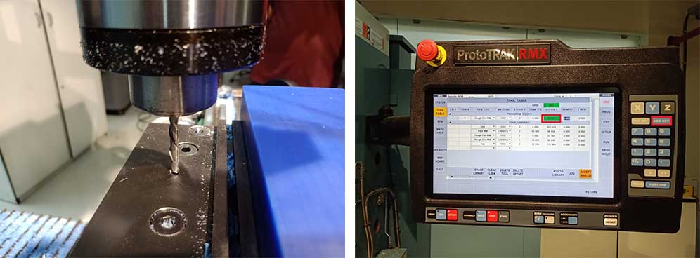
Insert the tool holder and tool in the spindle → If the newly created tool →Press the tool against the base →Select “Z offset” → Press “Set absolute ” to set the tool offset.
-
Set Z origin
- Move to → DRO → JOG
- Jog the tool just above the wax block
- Release the quill and press it against the wax → exit JOG → Press Z → Press “Set absolute ” to set the Z origin.
-
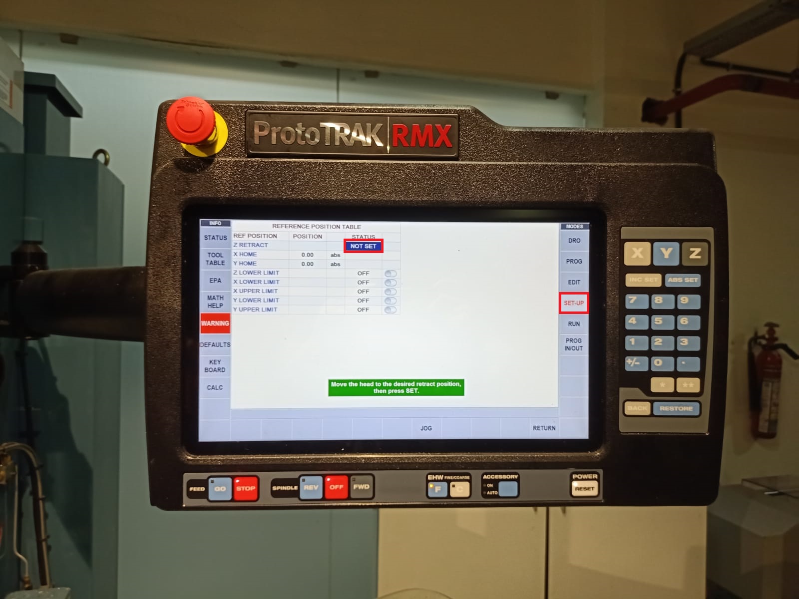
Set safe retract → Move tool Z-axis_ a few centimeters away from the wax block
- Go to setup → select the Z to retract status button → Press “Set absolute ” to set the Z safe to retract height
-
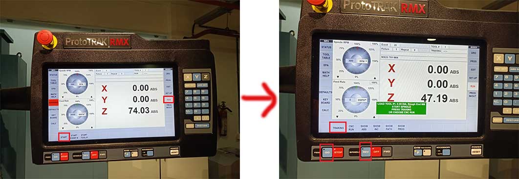
Considering the safety of machine and operator It is better to start GCODE Manuel feed
-
Go to → “RUN” → “Start” → ”Tracking”→ Press Spindle “REV” → Press “FEED GO”
-
Rotate the jog wheel to manually feed the machine (Rotate clockwise to advance in GCODE rotate anticlockwise to travel backward in GCODE)
-
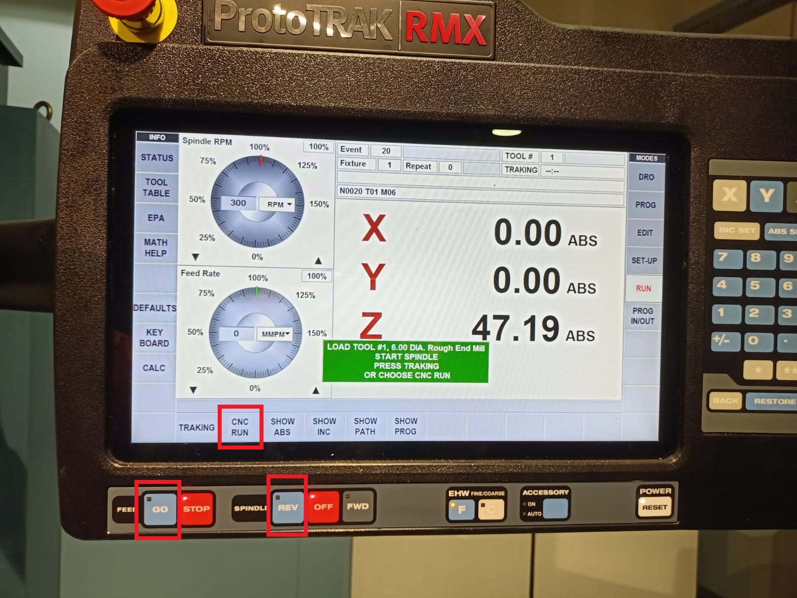
if everything is okay press “FEED STOP”
- Press “CNC Run” → Press “FEED GO”
-
I had to do 2 more operations according to the files I generated in Fusion 360.
For each operations, I changed tool bits(6 mm ball endmill and 1/16 mil flat endmill)
Procedure for repeating operations are given below.
- Tool Change → raise Z axis → hold hands on the tool holder → release tool by pressing the” tool” out button in the pneumatic control box.
- Insert the new tool
- Press “program In/Out” → Select 2nd GCODE file
- Go to “Tool Table”
- Press JOG and move the tool close to the base point (Back of vise)
- select the tool for the operation → If not create a new one by specifying the type and diameter
- Insert the tool holder and tool in the spindle → If the newly created tool →Press the tool against the base →Select “Z offset” → Press “Set absolute ” to set the tool offset.
-
Go to → “RUN” → “Start” → ”RUN CNC”→ Press Spindle “FWD” → Press “FEED GO”
tool changing video
Molding using OOMOO 37
We used OOMOO 37 for casting the mold.
Before that we had opened the OOMOO 25. But it was clotted.
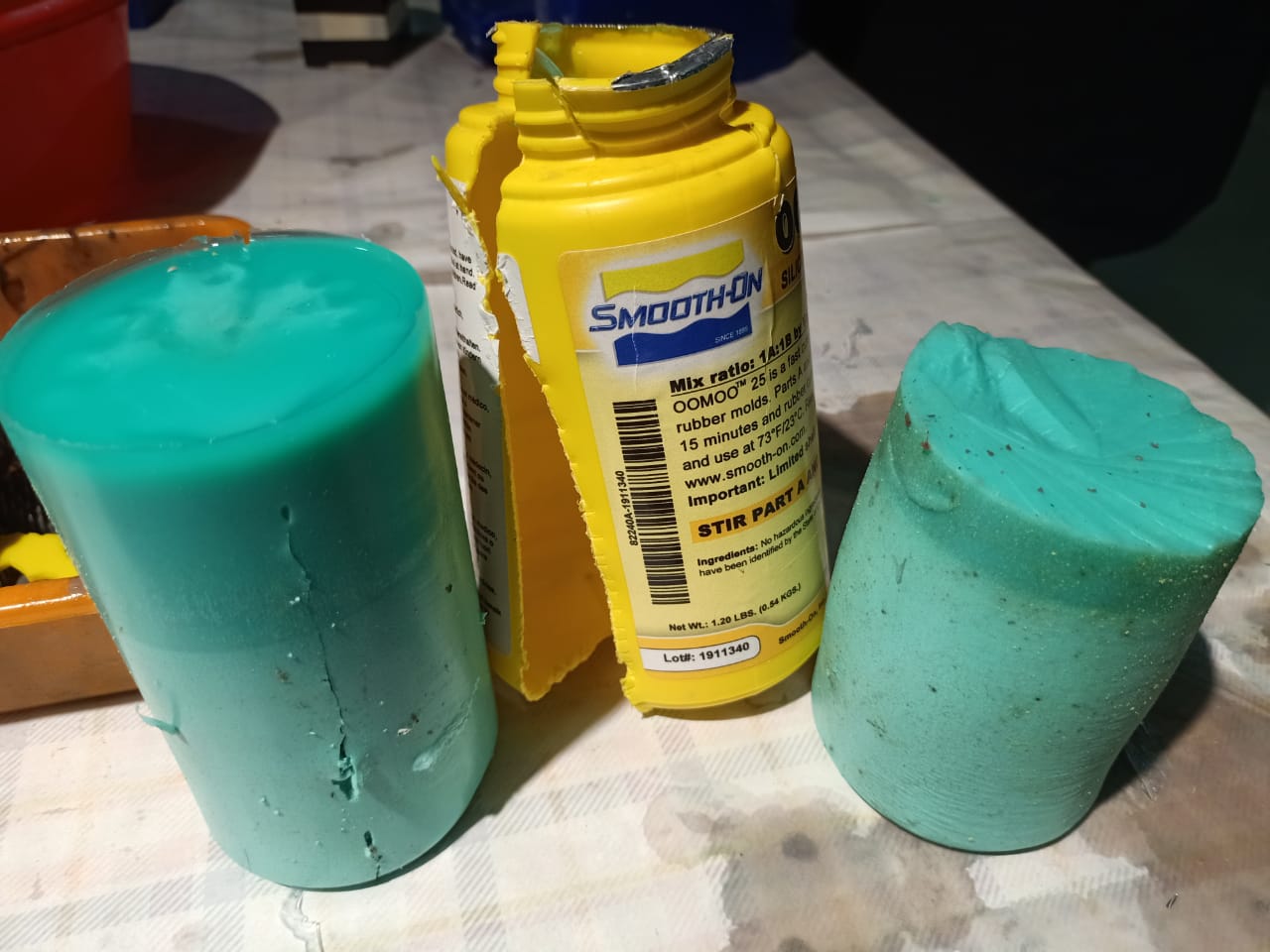
At first, we read the datasheet.
Important parts in the datasheet.
I wore gloves, mask and windshield,
The steps I followed are given below.
- pour water into the milled part, pour that water into a transparent cup(for calculating the volume of mold).
-
Divide that water into two cups equally and mark levels using a marker.
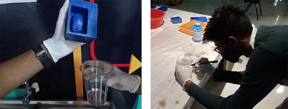
-
Remove the water and pour parts A and B in different cups up to the level marking(Shake well each bottle before pouring).
-
Mix Part A and B in a cup and mix well. (Keeping in mind that mixing should be done gently so that air is not introduced into the material. Minimizing bubbles is important.)
-
Pour the silicone into the mold. (It was very difficult because our silicone was found to be bit more tight due to expiration, and there was a lot of bubbles in the mix)
-
Wait for 4 hours and remove cast from mold
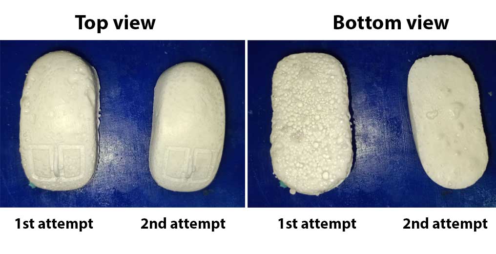
Here is the result I got.
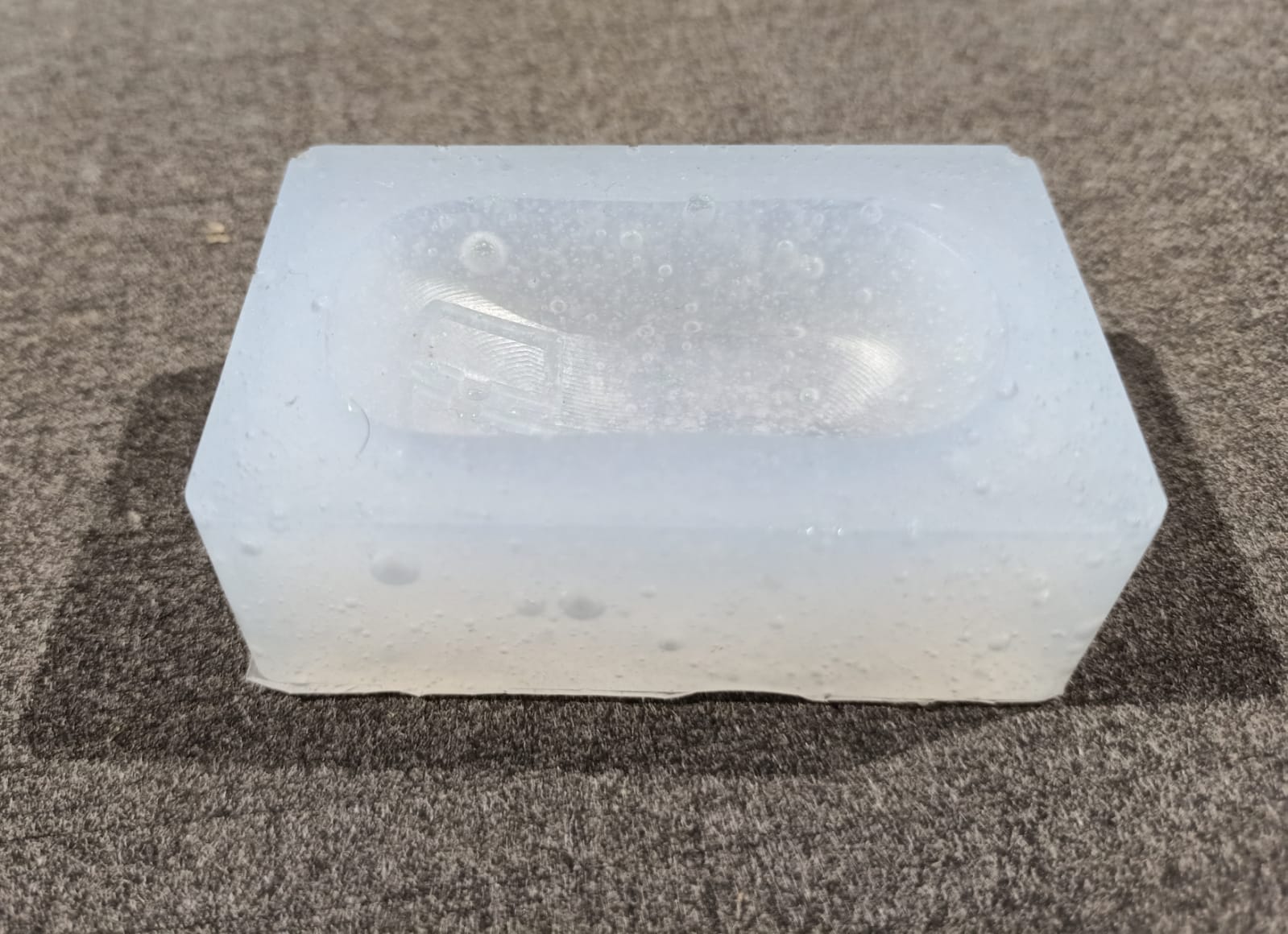
Pouring the silicone into the wax mold.
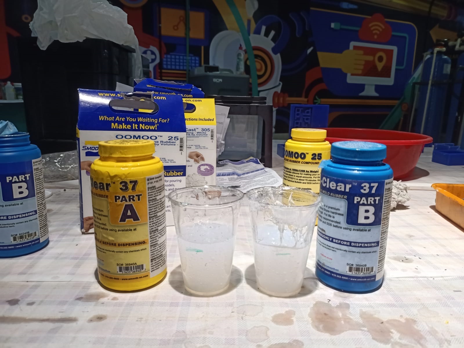
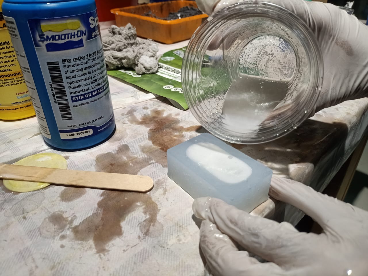
Casting using Smooth-On
We used Smooth-On liquid plastic to mold.
Steps:
- Read datasheet.
- Measure the volume for casting as followed in previous casting(Take water in mold and divide into 2 cups and mark the level)
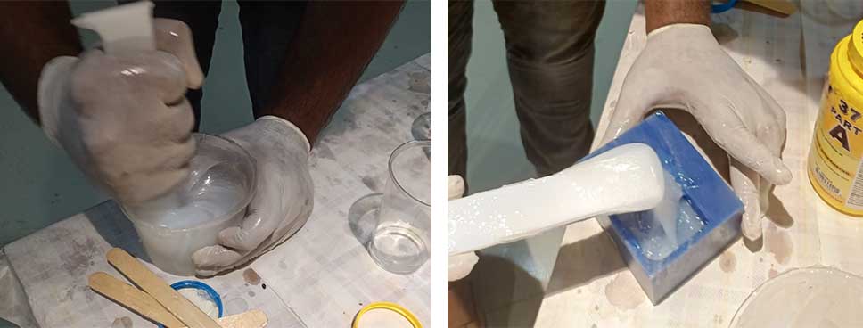
- Measure Part A and Part B in different cups and mix in a beaker. (In the first attempt my stiring was not good, So there was a lot of bubble in the mix. )
- Pour the mix into the silicone mold.
It takes only 20 minutes to set the cast.
- Removing the cast from mold.
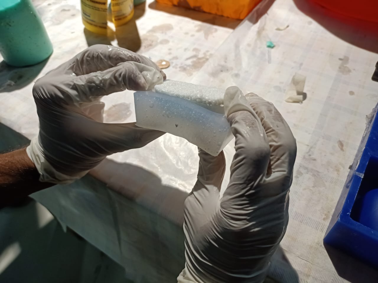
My casted result was full of bubbles. So I repeated the casting once more.
In that time I stir the mix very carefully and properly.
Then the result was better. But there were a few bubbles.