9. Embedded programming
Task: Embedded Programming
- Group assignment:(Page Link is Here)
- Compare the performance and development workflows for other architectures
- Document your work to the group work page and reflect on your individual page what you learned
- Individual assignment:
- Read the datasheet for your microcontroller
- Use your programmer to program your board to do something
When I was in tenth grade, I worked in an electronics repair shop. But, I was unable to study anything in depth during that time.
Until recently, I had no idea how to connect an IC to a circuit board. And my assumption was that most device circuits are very complex, with logic gates. Now I’m very confident and happy because I realized we can make circuits without using logic gates; instead, we can use a small integrated circuit (IC).
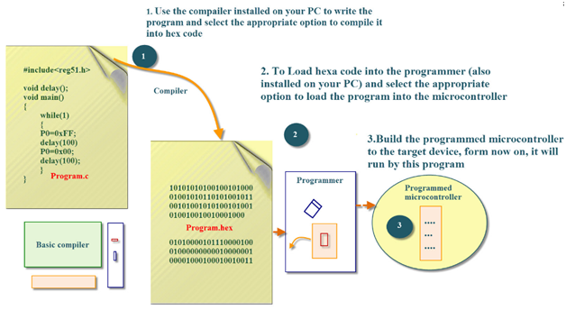
In this week, at first, I tried to understand what is the use of embedded programming.
ref: javatpoint.com
What is hex code?
Hexadecimal (base 16 - 0 1 2 3 4 5 6 7 8 9 A B C D E F) is used as a shortcut notation for binary numbers (0 1) because it works out nicely for 8, 16, 32, and 64 bit processors. You can represent all binary numbers with each set of 4 bits as 1 hex character A=1010, B=1011, F = 1111, 0 = 0000, 7 = 0111, etc.
Compilers of languages and even down to assemblers can instantly decode hex numbers to binary numbers and send them as data or cpu instructions into the cpu or to memory.
ref: brainly.in
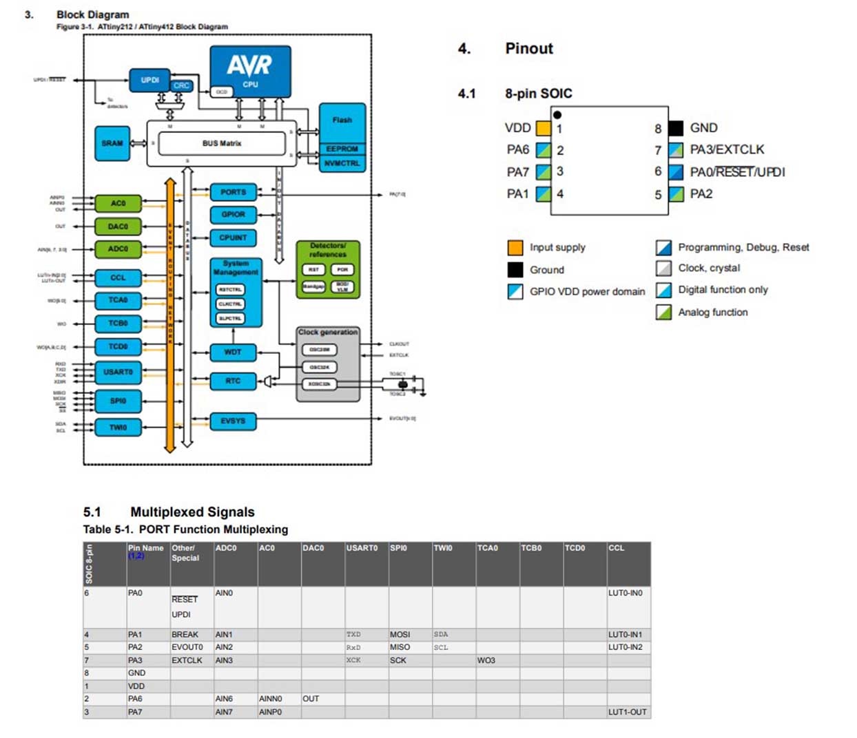
Understand about datasheet.
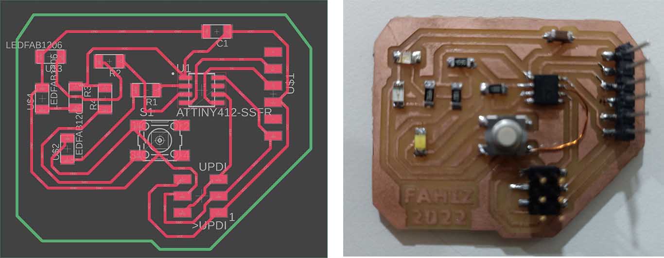
We are using ATtiny 412 microcontroller in our board that made in electronics design week.
I downloaded the datasheet from the internet and tried to understand different portion.
Some important portions in a datasheet.
Device Designations

Block diagram and Pinout diagram
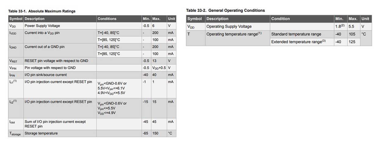
Supply characteristics
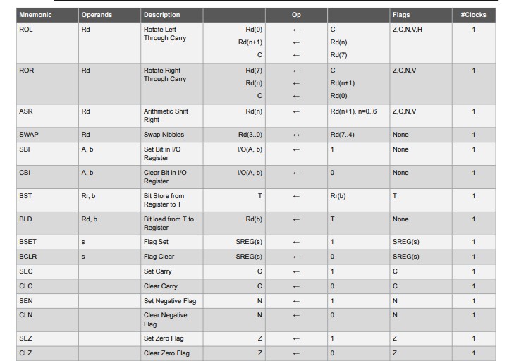
Instruction set summary
Programming
I watched a video of 3 hours on YouTube about C programming(Link here)
Website of our mentor Rahul helped me to understand bit shifting operations and other parameters(Link here). Our senior, Saheen Palayi, explained about the operations to us.
Program the microcontroller.
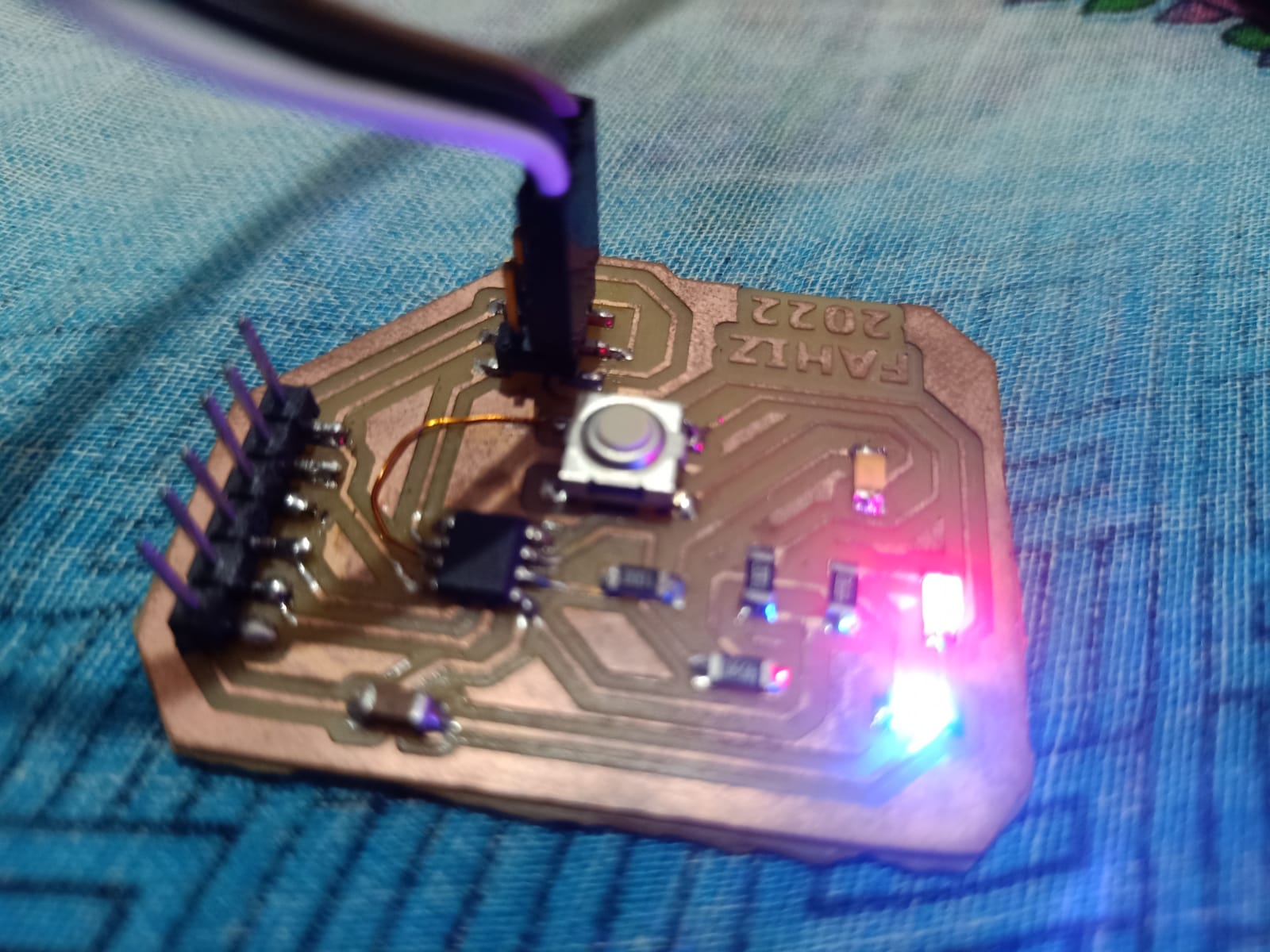
I had made a 2 led and one switch board using ATtiny 412. For programming I used different IDEs.
Arduino IDE
I programmed my ATtiny 412 using Arduino IDE in Electronic design week.
Steps are given below.
- Add MegaTinyCore through the Arduino IDE’s board manager.
- Connect the board through UPDI.
- Select chip and port in the Tool menu.
- Write code in Arduino IDE.
- Click on the Upload button.
code:
const int buttonPin = 4;
const int ledPin_1 =  0;
const int ledPin_2 =  1;

int buttonState = 0;
void setup() {

  pinMode(ledPin_1, OUTPUT);
  pinMode(ledPin_2, OUTPUT);

  pinMode(buttonPin, INPUT);
}

void loop() {

  buttonState = digitalRead(buttonPin);

  if (buttonState == HIGH) {

    digitalWrite(ledPin_1, LOW);
    digitalWrite(ledPin_2, HIGH);
  } else {

    digitalWrite(ledPin_1, HIGH);
    digitalWrite(ledPin_2, LOW);
  }
}
Using pyupdi in CMD
For that, we have to install pyupdi on the computer. I have already installed it.
Steps for the program using CMD are given below.
- Write code in Arduino IDE and save it.
- Go to Sketch → Export compiled binary. (Then a .hex, .lst, .map will add in the file saved location)
- Open the command prompt as run as administrator and type ‘pyupdi.exe’ to check pyupdi exist or not.
- type code in the format pyupdi.exe -d device name -c port name -b 9600 -f “hex file.hex”
pyupdi.exe -d attiny412 -c COM6 -b 9600 -f "C:\Users\nihal\Desktop\fahiz's fab\Assignments\week09\file\Button_test\Button_test.hex”
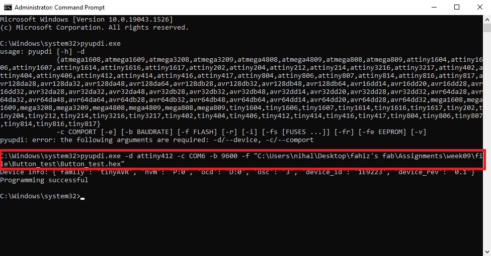
Then my board successfully programmed.
Using Embedded C
Atmel Studio is an IDE to write, build, and debug applications written in C/C++ or assembly code.
The steps I followed are given below.
- Download (Link) and install Atmel Studio.
-
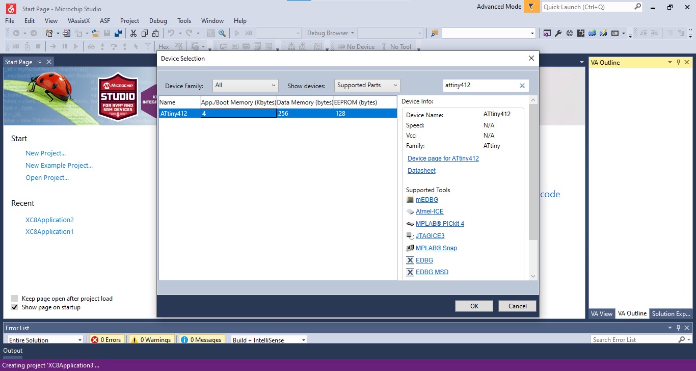
Open and go to File → New → Project
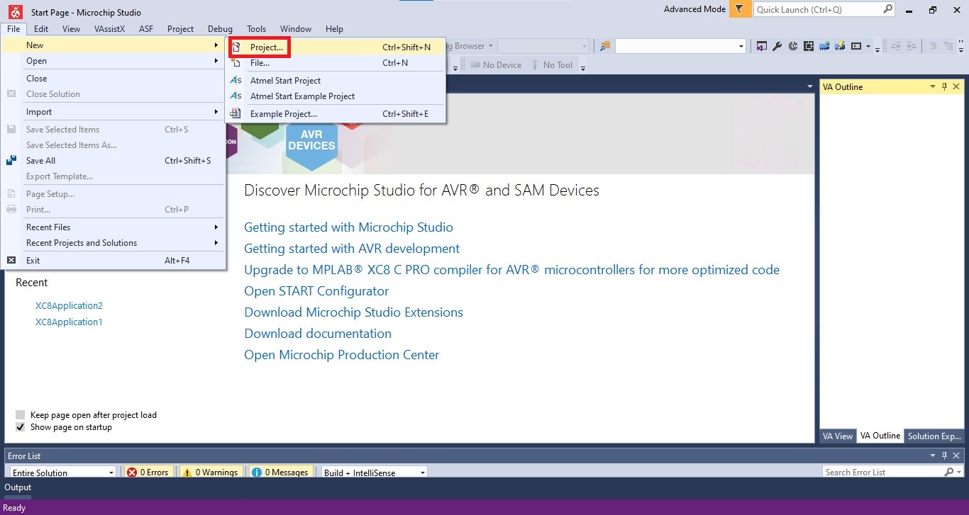
In the C/ C++ option select AVR XCB C Application Project and click OK.
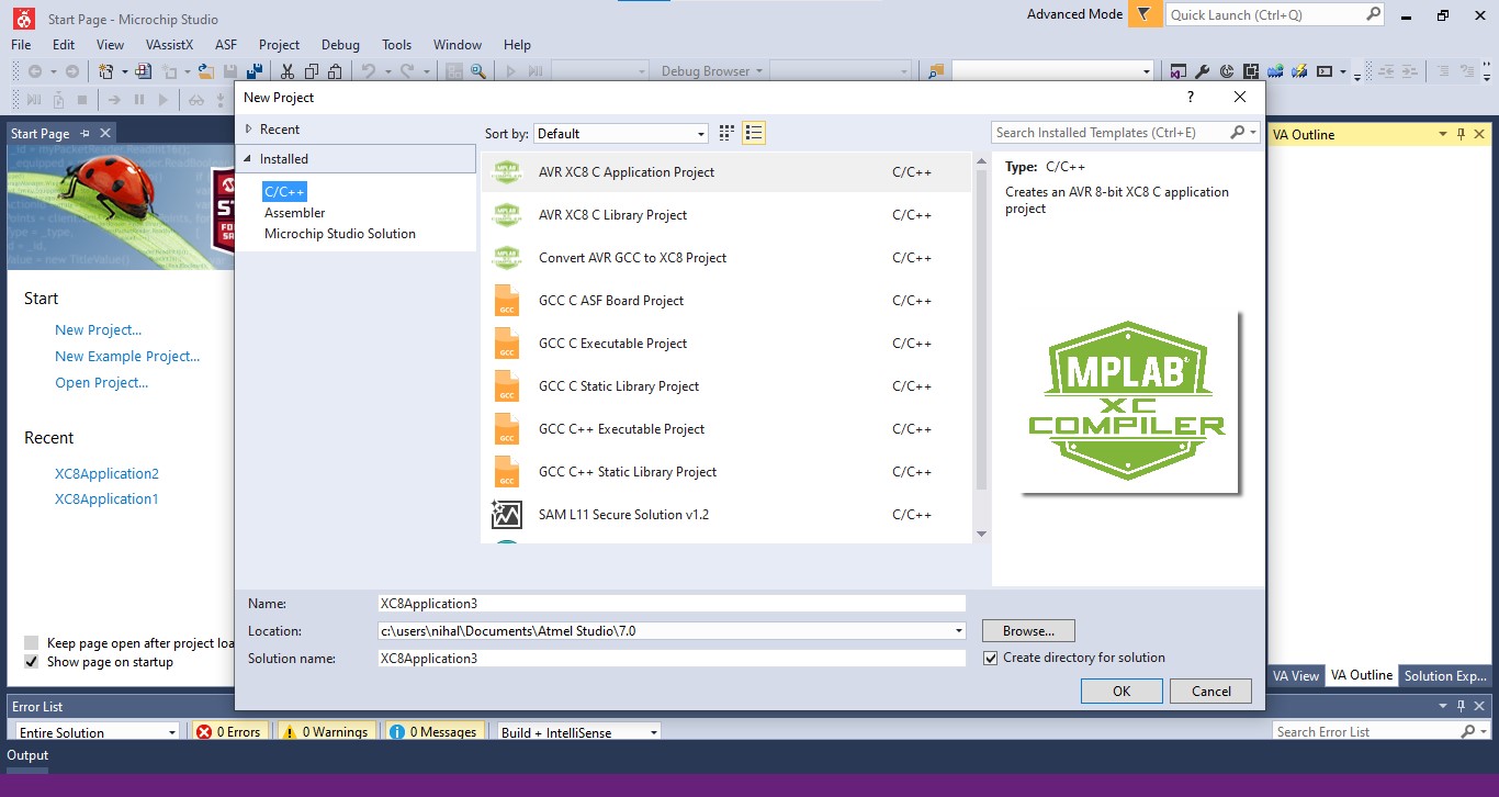
In the Device Selection window, select ATtiny412.
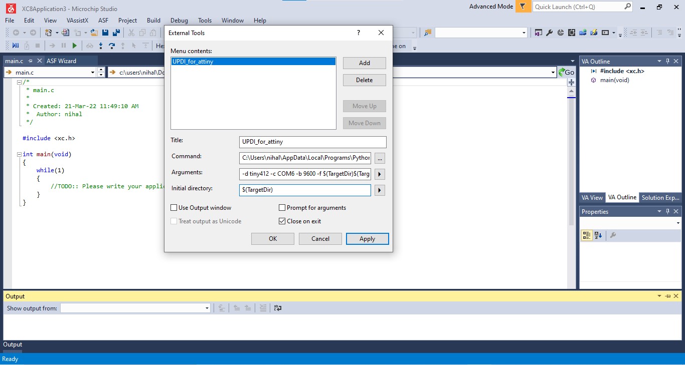
- In the opening window, Go to Tools→ External Tools and inhere we can add external tools here. I filled each column as given below and clicked on Apply. Title: UPDI_for_attiny Command: C:\Users\nihal\AppData\Local\Programs\Python\Python310\Scripts\pyupdi.exe (It is the navigation to the pyupdi script) Arguinment: -d tiny412 -c COM6 -b 9600 -f $(TargetDir)$(TargetName).hex (In here tiny412: Device name COM6 : Port name. b 9600 : It is the baud baudrate $(TargetDir)$(TargetName).hex : Navigation to hex file. Initial directory: $(TargetDir)
- Use the code below to blink one LED.
#include <avr/io.h>                    // AVR input/output library

#define F_CPU 3555555                // Since we connected a 20MHz crystal into the circuit

#include <util/delay.h>                // Delay library

#define LED 0b01000000

int main()

{

  PORTA_DIRSET = (1<<6);                       //set pins 7 in the A port as output pins.

  while(1)                           // infinte loop

  {

    PORTA_OUT |=(1<<6);                 //Turns pin7 ON.

    _delay_ms(1000);               //wait for one second.

    PORTA_OUT &=(!(1<<6));              //Turns pin7 OFF.

    _delay_ms(1000);               //wait for one second.

  }
}
- Go to Build → Build solutions
-
Go to Tools → UPDI_for_attiny
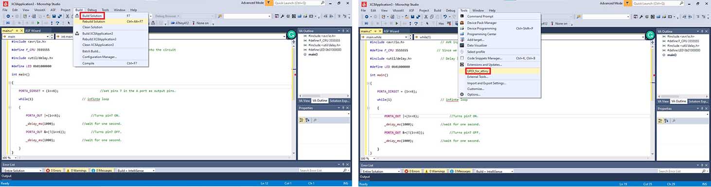
-
Then my board successfully programmed.
Using Assembly language
What Is an Assembly Language?
Assembly Language is a low-level programming language. It helps in understanding the programming language to machine code. In computers, there is an assembler that helps in converting the assembly code into machine code executable. Assembly language is designed to understand the instruction and provide it to machine language for further processing. It mainly depends on the architecture of the system, whether it is the operating system or computer architecture. ref:educba.com
Features of assembly language
- It allows complex jobs to run in a simpler way.
- It is memory efficient, as it requires less memory.
- It is faster in speed, as its execution time is less.
Joshwin helped me to understand assembly language and he explained about different instruction sets.
I programmed my board using assembly language in Atmel studio.
The steps I followed are given below.
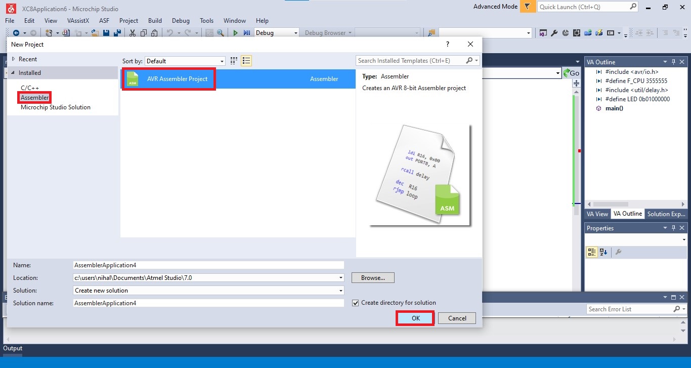
- In Atmel studio, go to File→ New → Project
-
In the Assembler option select AVR Assembler Project and click OK.
-
I used a code to blink LED for for 2 clock cycle. The code is given below.
.include "tn412def.inc"
; Replace with your application code
  sbi  VPORTA_DIR,7; PB0 as output, driver stage on, 2 clock cycles
Loop:
  cbi VPORTA_OUT,7 ; LED on, 2 clock cycles
  nop ; do nothing, 1 clock cycle
  nop ; do nothing, 1 clock cycle
  sbi VPORTA_OUT,7 ; LED off, 2 clock cycles
  rjmp Loop ; Jump relative back to label Loop, 2 clock cycles
- the rest of steps are same as C.
Using AVRDUDE in Atmel studio
I downloaded Avrdude and WinAVR and Adafruit driver.
And I added Tool in Atmel studio.
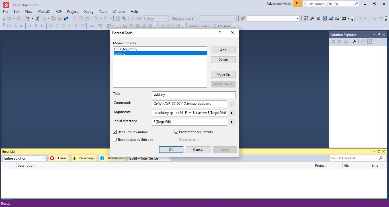
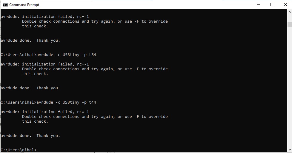
I tried to program an attiny44 using this but I couldn’t connect to it.
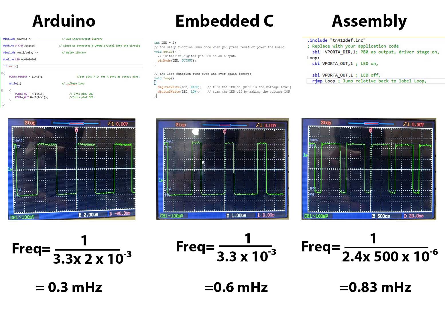
Group assignment.
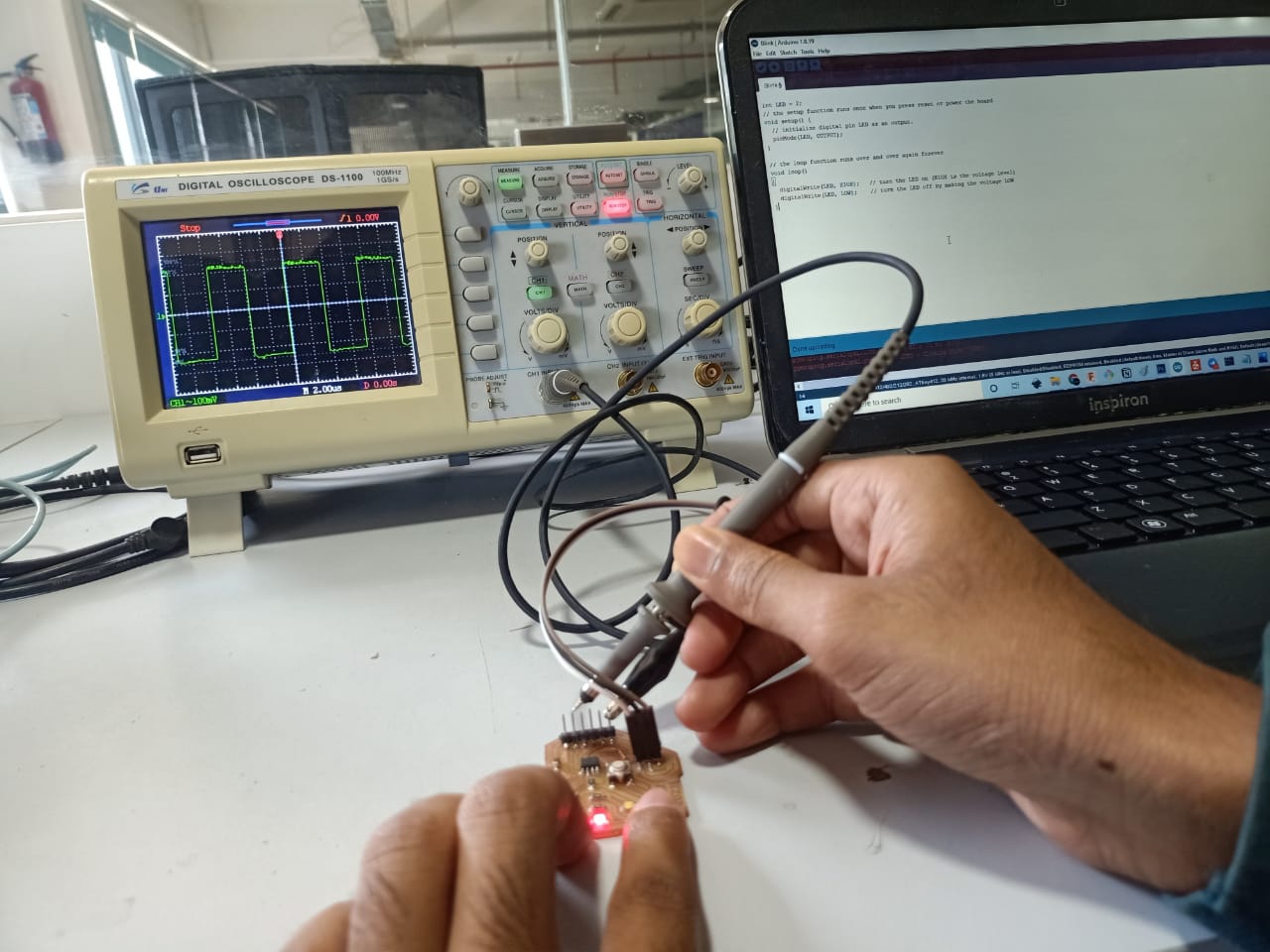
We found the speed of different programming languages and IDEs.
For that programs code for blinking LED with 0 clock cycle gap in Arduino, Embedded C and Assembly language.
Instead of LED pin, we give a pin of RXD.
And we checked the signal using Digital Oscilloscope.
The codes are given below.
int Pin_num = 2 ; // It is the pin of RXD
void setup() {
// initialize digital pin Pin_num as an output.
pinMode(Pin_num, OUTPUT);
}
// the loop function runs over and over again forever
void loop() {
digitalWrite(Pin_num, HIGH);   // turn the LED on (HIGH is the voltage level
digitalWrite(Pin_num, LOW);    // turn the LED off by making the voltage LOW
}
#include <avr/io.h>                    // AVR input/output library
#define F_CPU 3555555                // Since we connected a 20MHz crystal into the circuit
#include <util/delay.h>                // Delay library
#define LED 0b01000000

int main()
{
  PORTA_DIRSET = (1<<6);                       //set pins 7 in the A port as output pins.
  while(1)                           // infinte loop
  {
    PORTA_OUT |=(1<<6);                 //Turns pin7 ON.
    PORTA_OUT &=(!(1<<6));              //Turns pin7 OFF.
  }
}
.include "tn412def.inc"
; Replace with your application code
sbi  VPORTA_DIR,7; PB0 as output, driver stage on,
Loop:
cbi VPORTA_OUT,7 ;
sbi VPORTA_OUT,7 ;
rjmp Loop ;
Nucleo
We tried to program Nucleo board.
Steps are given below.
- Open Arduino IDE, Go to File → Preference→ Additional Boards Managers URLs, paste the code below
**https://github.com/stm32duino/BoardManagerFiles/raw/main/package_stmicroelectronics_index.json**
- Go to Tools→ Board→ Board manager and install STM32 MCU based boards.
- Go to Tools→ Board→ STM32 boards groups and select Nucleo-64
- Go to Tools→ Board part number and select Nucleo F303RE
- Connect Nucleo F303RE through USB port.
- Go to Tools → Port and select serial port
- Write code to blink LED. (Pin 13 is the pin connected to LED)
#define LED 13
void setup() {
// initialize digital pin LED_BUILTIN as an output.
pinMode(LED, OUTPUT);
}
// the loop function runs over and over again forever
void loop() {
digitalWrite(LED, HIGH);   // turn the LED on (HIGH is the voltage level)
delay(1000);                       // wait for a second
digitalWrite(LED, LOW);    // turn the LED off by making the voltage LOW
delay(1000);                       // wait for a second
-
Click on Upload button.
Download code files from here → Download