4. Computer controlled cutting
Objectives
Group (To redirect to group assigment page Click here)
- Characterize lasercutter’s focus, power, speed, rate, kerf, joint clearance and types
Individual
- Cut something on the vinylcutter
- Design, lasercut, and document a parametric construction kit, accounting for the lasercutter kerf, which can be assembled in multiple ways, and for extra credit include elements that aren’t flat
Vinyl Cutting
Setting up the machine
- Release the loading lever and set the friction roller and the vinyl inside the cutter make sure the rollers are placed on the white markings and vinyl is paralell to the guide lines on the cutter now engage the lever.
- Turn on the power and select accodingly whether it is a PICE or SHEET.
- Optimizing the machine by changing the cutting tool, cutting speed, Tool offset, or cutting force.
- Now set orgin using navigation buttons and press ORGIN
- Press the TEST button for a few seconds.
- Using a tweezer pull the cutted vinyl and redo the process to calibrate the machine to get a optimum result.
Creating .png file for cutting via Mods
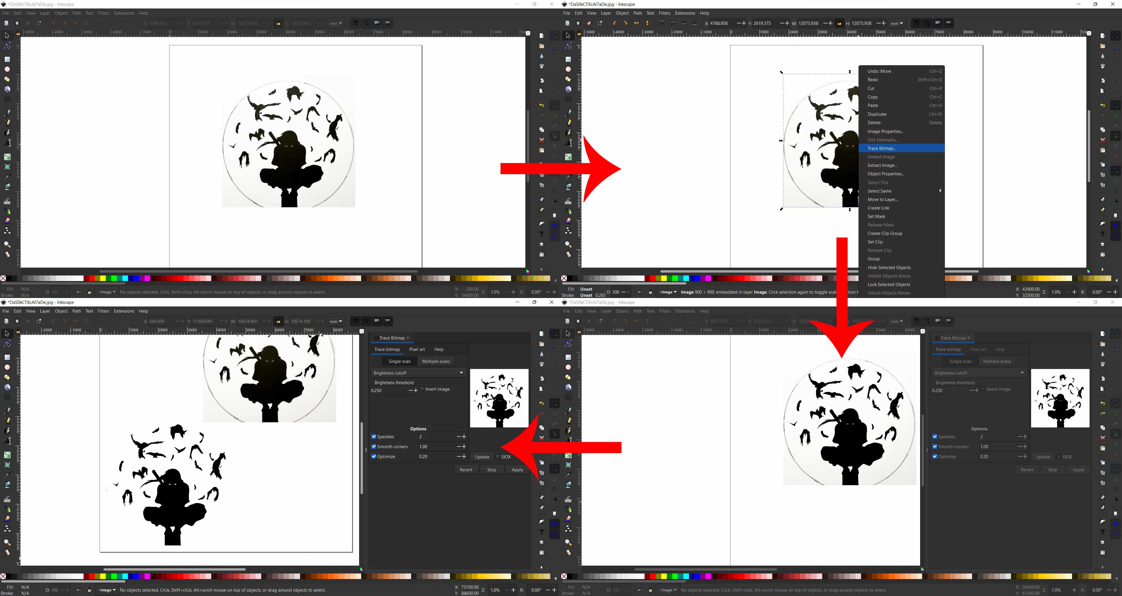
Downloading an image from internet and use any vector software to trace bitmap and export it as .png file to upload on mods platform
Mods is an open-source modular digital manufacturing CAM software developed by MIT’s Center for Bits and Atoms (CBA). Resulting, in a single software controlling any machine from a computer. It can communicate with Laser cutters, vinyl cutters, and CNC mills.
for downloading file Click here
Opening Mods by CBA
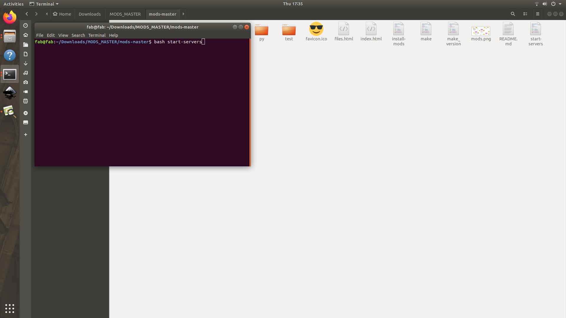
Next step is to bash the local server on your working PC which is connected to the Vinyl Cutter use the code below to bash the file change “start-servers” to whatever the file is named in your directroy
bash start-servers
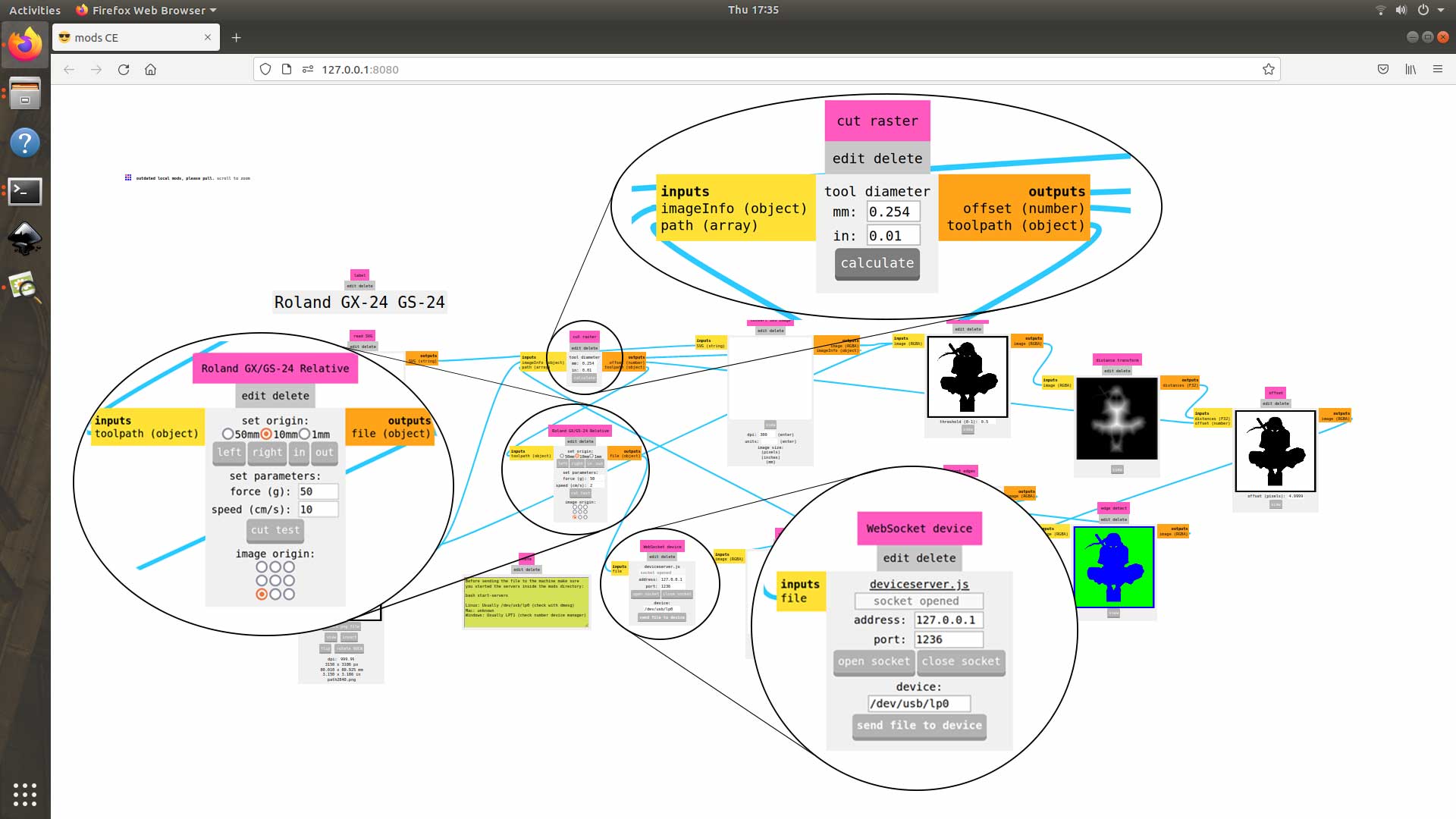
Setting up and sending files via Mods
Select the machine from the landing page and upload the image in the Read Png node and click calculate in Cut Raster node set offset and cutting speed appropriately now click on send file to device in WebSocket device
Cutting
Just Before cutting check the orgin and if needed set te orgin again
Applying vinyl
The unwanted parts from the output is carefully removed and the product is sticked to the required surface with an application tape.
Final Output

Laser Cutting
Setting up the machine
Setting up a laser engraver is easier than setting up a vinyl cutter. To begin, turn on the machine and, using the navigation buttons on the control panel, Focus the laser head to the place where the cut will be performed.
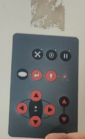 then lower the bed a little, then gently raise the bed till the key tips off, to set the Focus on the laser head.
Group Assigment
Kerf
During any cutting process, the cutting tool causes some excess material to be lost in addition to the specified design. When a laser cuts a material, its path burns off some material, known as the kerf of a laser cutter.
Design for teting kerf
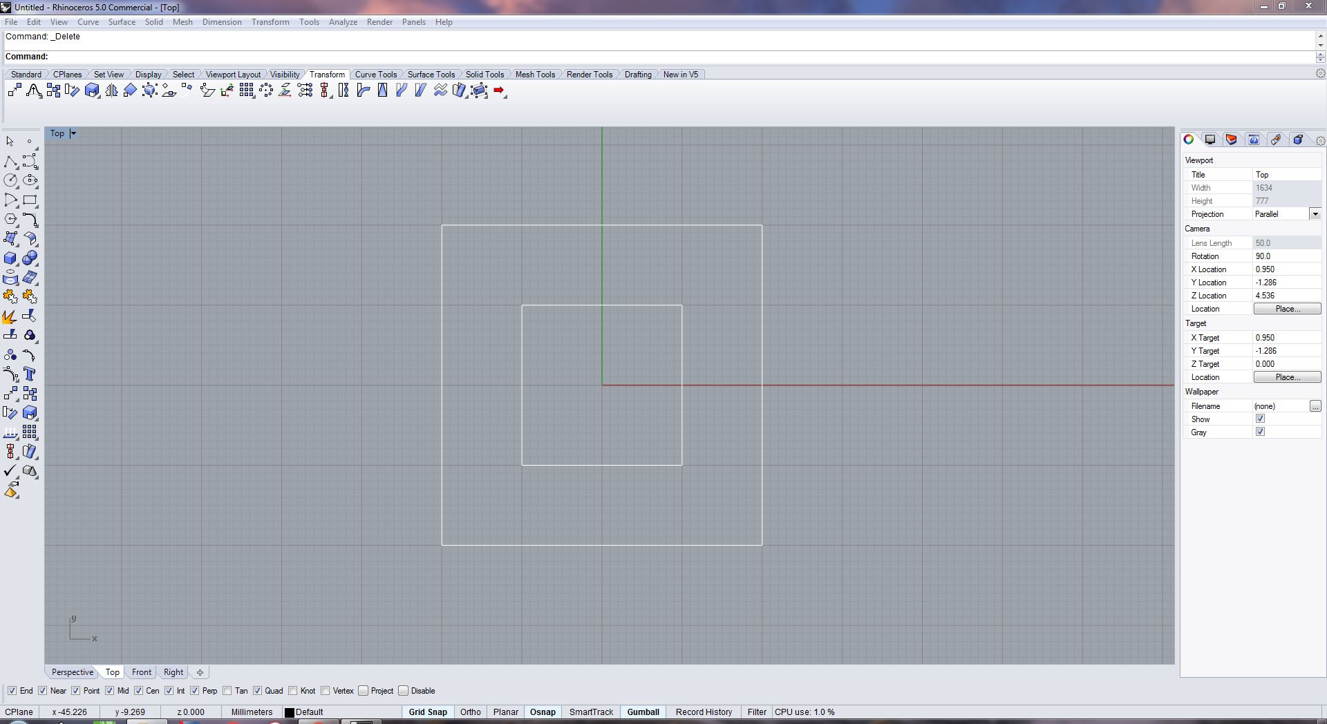
We decided to make a simple design of a square with a 20mm side within a square with a 40mm side to calculate kerf. We began to draw the design within Rhinoceros 3D because the design is very basic.
for downloading file Click here
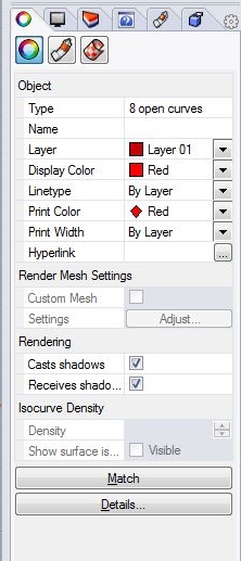
Design properties
The Layer attributes (side ribbon) were set up as, Display color as Red, Linetype as continuous, Print color as Red, Print width as hairline
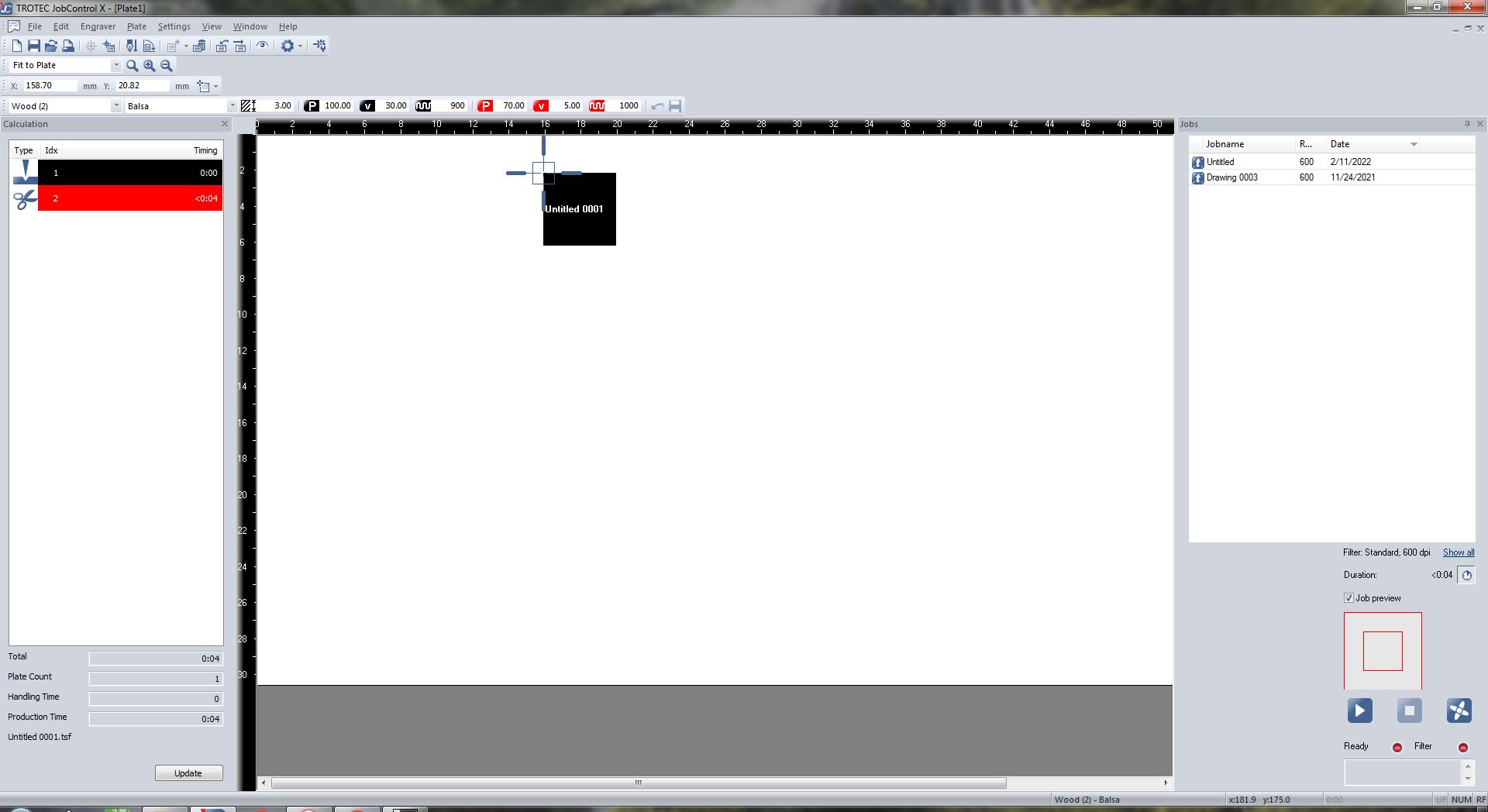
Setting up Cutting/Engraving properties
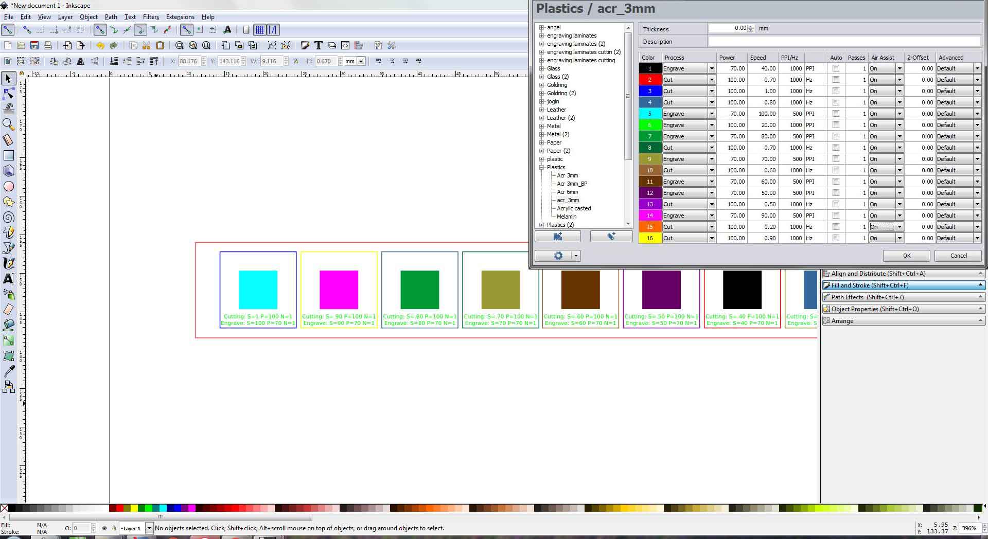
We’ll use Ctrl+p to redirect to print properties, where we’ll make sure the print settings are set to 1:1 and the design is in the pintable region, before moving on to cutting/engraving parameters. If this is not the case, take appropriate action.Now select the printer as Trotec After being sent to the TROTEC Job Control window, we may pick the presets for different materials on the top ribbon, then click the highlighted button to change the settings further. Make any necessary modifications, and then drag and drop the design to the task area and put it where the cut would be done; if it is brought to the head pointer, it will automatically snap to it.
Cutting Parameters used
We created a file as shown below and adjusted the settings in the job control to find the best cutting parameters for each material, maintaining power constant and speed ranging from 100cm/sec to 20cm/sec for engraving and 1cm/sec to.2cm/sec for cutting *the values may change as per the meterials used.
 for downloading file Click here
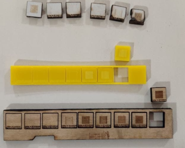
The materials were cut to determine the value for producing the best cut, however, the values provided for the cardboard were a little too high, so we increased the speed to 1 for cutting.
- Acrylic
Cutting Power=100
Engraving Power=70
Cutting Speed=0.4cm/sec
Engraving Speed=60cm/sec
Number of passes=1
Frequency=1000 - Wood
Cutting Power=100
Engraving Power=70
Cutting Speed=0.2cm/sec
Engraving Speed=60cm/sec
Number of passes=1
Frequency=1000 - Cardbord
Cutting Power=100
Engraving Power=70
Cutting Speed=1cm/sec
Engraving Speed=60cm/sec
Number of passes=1
Frequency=1000
Test and Calculation
We measured the inner diameter of the square hole within the cutout component using a digital vernier, then the exterior dimension of the removed piece.
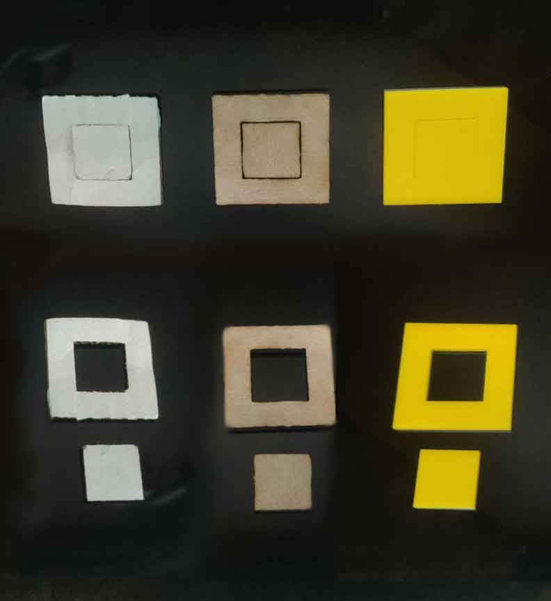
Now we can determined kerf by subtracting the inner from the outer dimension and then dividing by two.
- Acrylic
20.20-19.87= 0.33
kerf=0.33/2
kerf=0.165 - Wood
20.41-19.8= 0.61
kerf=0.61/2
kerf=0.305 - Cardbord
20.35-19.84= 0.51
kerf=0.51/2
kerf=0.255
Made a small calculator for finding kerf.
Kerf Calculater
*please enter the larger number first
Metal Engraving
We tried engraving on a metal PCB board with the Trotec 400 flexx, experimenting with different engraving parameters and discovered that PCB prints at power 100 and speed 10cm/sec with 20 passes * for both cutting and engraving we need to select Cut FLP and Engrave FLP respectively
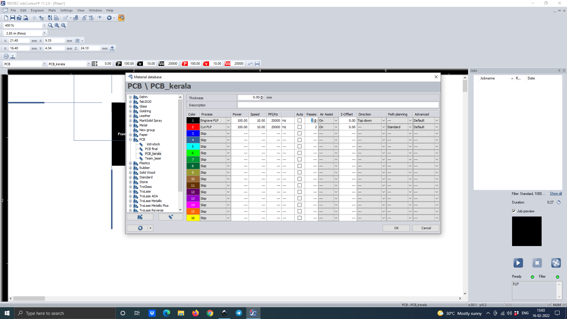
These are the results we got
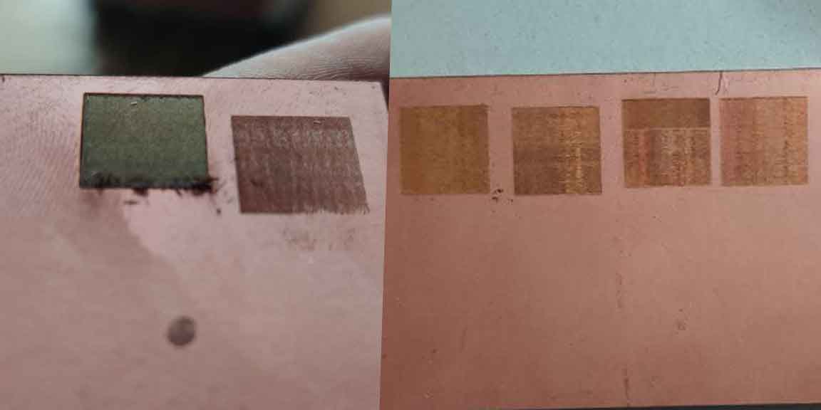
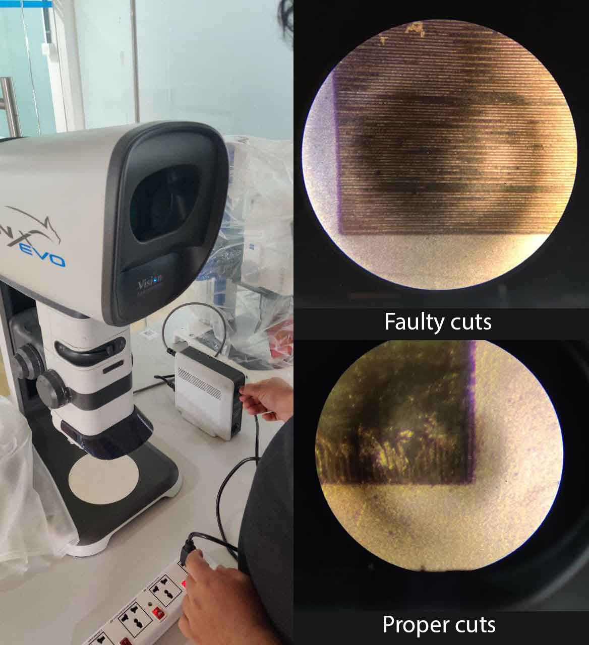
We used a 3D stereo microscope called the Lynx EVO to examine the cut. We discovered that faulty cuts make lined patterns, but proper cuts provide a smooth surface, and that we must clean the edges.
Pressfits
The clearance between the joining pieces is known as joint fits. There are three different types of fits: clearance, transition, and interference.
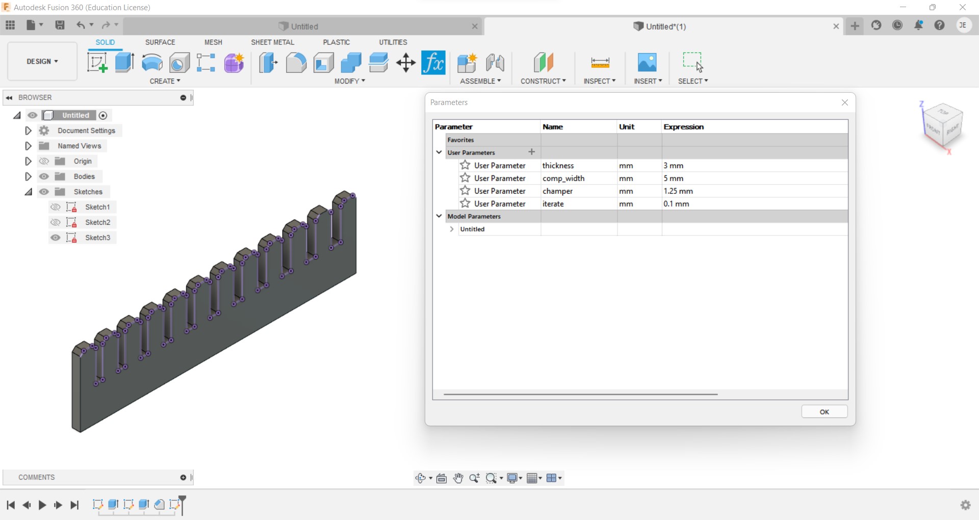
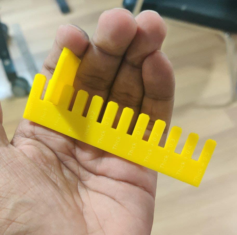
Designing a parametric jig
With a typical thickness of 3 mm, a parametrically built jig with slots ranging from 2.5 mm to 3.5 mm with 0.1 increment is disigned
with the same laser cutting setting previously used the jig is cutted out.With a 2.6mm slot, the fit was tight, implying that the hole’s dimension should be (thickness-kerf-overlap=3-0.165-0.235 = 2.6mm). To retain a tight fit, we need to keep a total overlap of 0.235 mm and 0.1175 mm on one side. This will be used to design the components.
for downloading file Click here
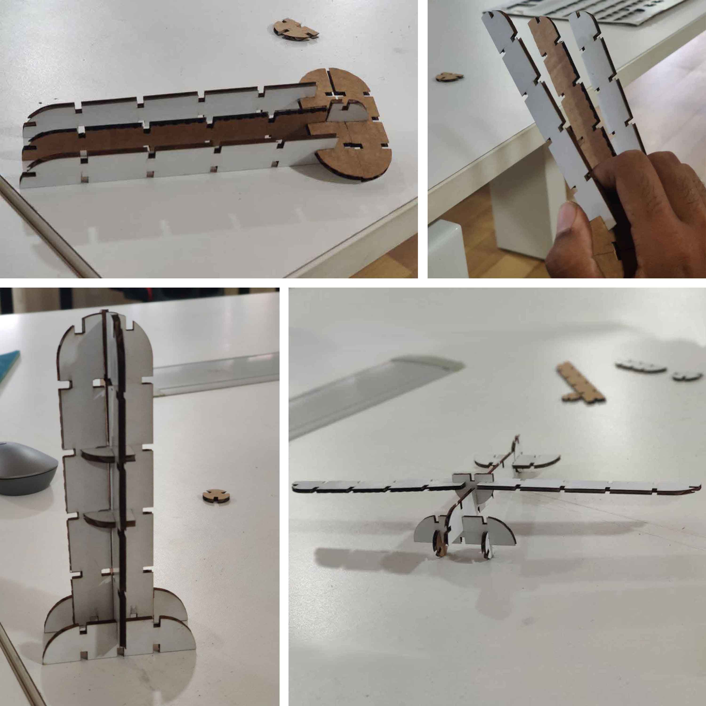
Pressfit construction kit
2 user parameters as thickness and kerf were added in the design to cut using different thickness sheet.
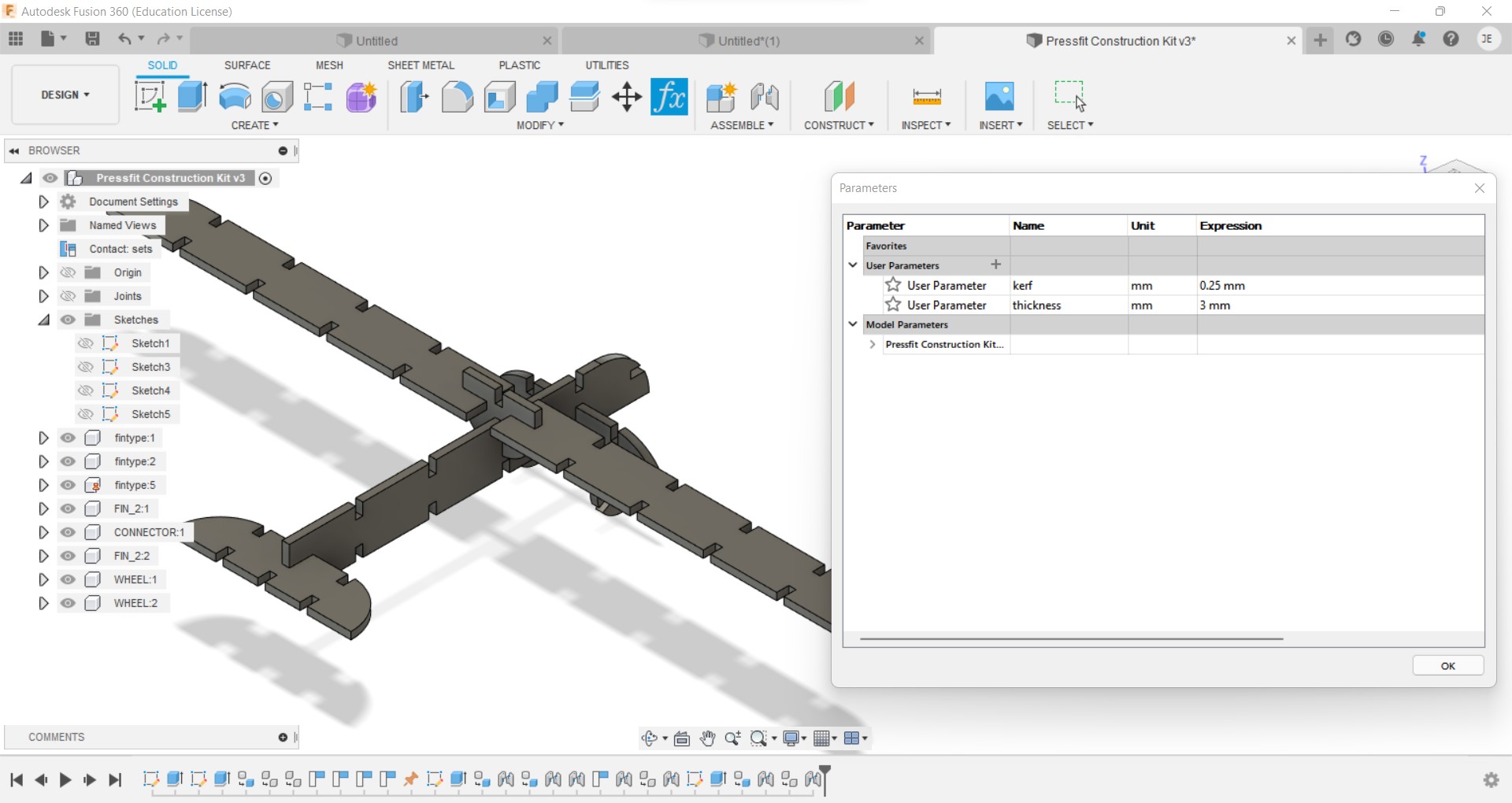
for downloading file Click here
this was exported to the cut
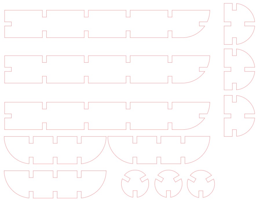
and then assembled to make different structures.
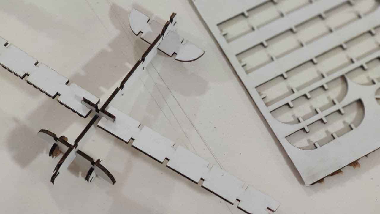
somemore structures from same modules