6. 3D Scanning and printing
Objectives
Group (To redirect to group assigment page Click here)
- Test the design rules for your 3D printer(s)
Individual
- design and 3D print an object that could not be made subtractively.
- 3D scan an object (and optionally print it).
3D Printer test
It’s vital, as usual, to determine the machine’s design rules to calculate the design parameters for creating the models to print. In our lab, we are using Prusa i3 MKS3.
Model for test print
for the test we downloaded a test file from thingiverse
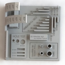
which included
- Overhanging test
- Hole test
- Bridge test
- Diamete test
- Support test
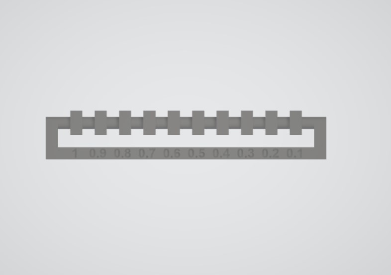
and took the clearence tesst file from academy page.
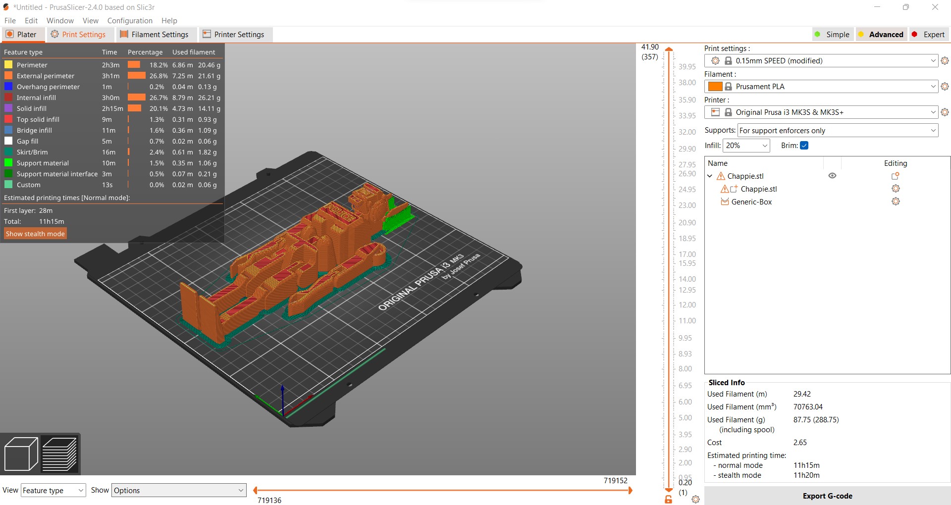
Slicing the model
A slicer is a program that turns 3D models into horizontal 2D layers that can then be printed layer by layer. It also allows us to give instructions to a 3D printer such as layer height, speed, and support structure settings. After downloading PrusaSlicer_2.4.0 from official prusa3d website. Import the models to the slicer by going to Flies > Import > Import STL/OBJ.... (Fig.2 in slider). Place the objects and click on Arange (Fig.3 in slider). To give support to the objects right click on the object > Add support enforcer > Box (Fig.5 in slider). Resize the supports and place it accordingly. Set the printer settings to
- Print settings: 0.20mm SPEED (modified)
- Filament: Prusament PLA
- Printer: Original Prusa i3 MKBS & MK3S+
- Supports: For support enforcers only
- Infill: 20% Click Slice Now now export the G-code (Fig.10 in slider)


Setting up and printing
To begin, select the required filament and load it into the printer. from the menu, pick unload Wait for the nozzle to preheat and the filament to unload and pull the filament out, then snip off the tip of the filament to be inserted and just slide it into the nozzle, where it will begin autoloading. Wait for the colour of the extruded filament to match the colour you require.
After inserting the SD Card and selecting the file to be printed, the printer will begin calibration after preheating the bed, and printing will start.
Result
After the printing is done we inspected the output models and found that (all results are as per the printed model)
- Over hang of 70 degrees could be printed without support
- Bridge width of 25mm is possible without support but the strength of the bridge is much lower
- Max tower height for the printer is 20mm
- Hole test, Dimeter test (1mm wall thickness) was comletely sucessfull
- For clearence we can take it till 0.2mm


Designing and 3D printing an object that could not be made subtractively
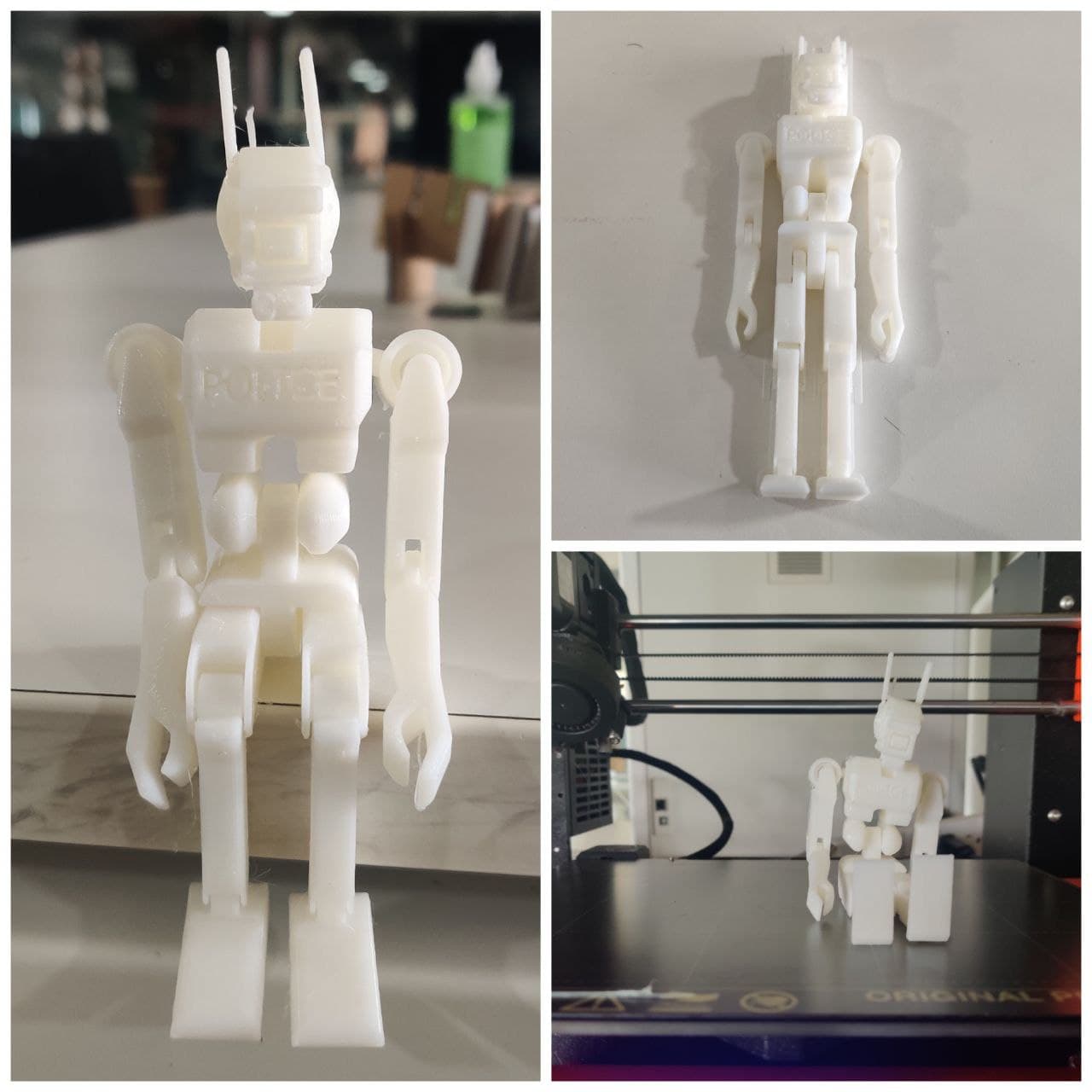
I was planning to create an articulated design, which would be a pre-assembled model that could be 3D printed. In Autodesk inventor, I created a character from one of my favorite film chappie. went through some reference images in internet.
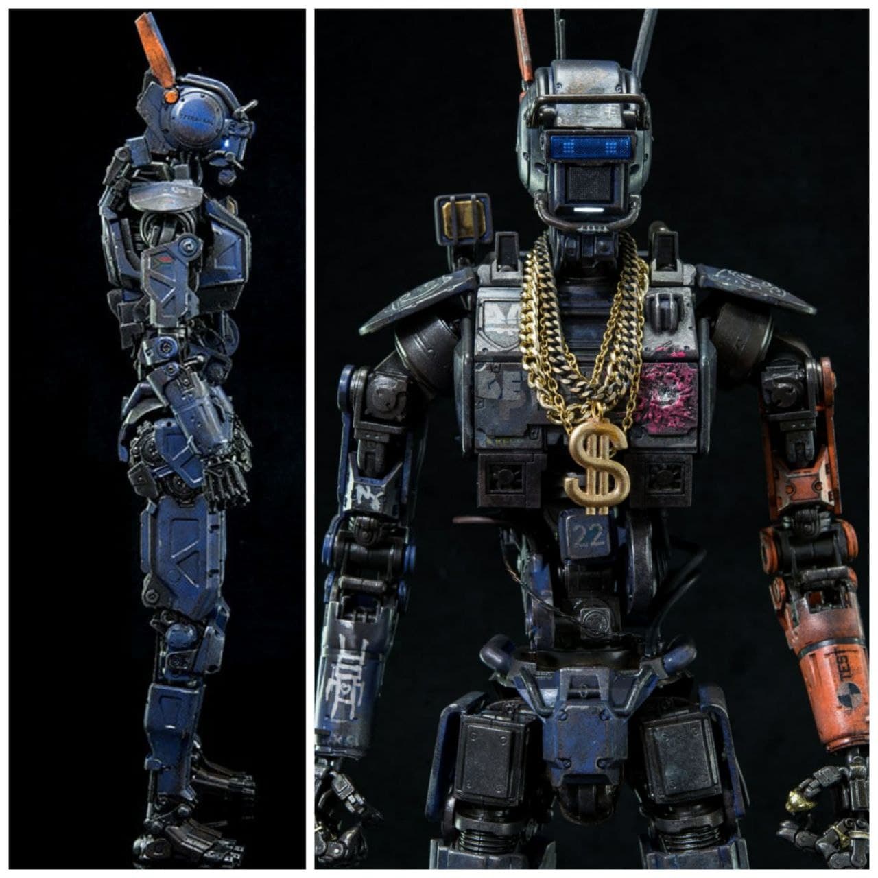
and started modeling.
Now as the designing process is done we can sent it to a slicer and generate G_code for 3D Printing with the same settings we earlier used.
the model was out for printing and i waited for hours to seee the final output.
the printed output was amazing. and ii really love it.
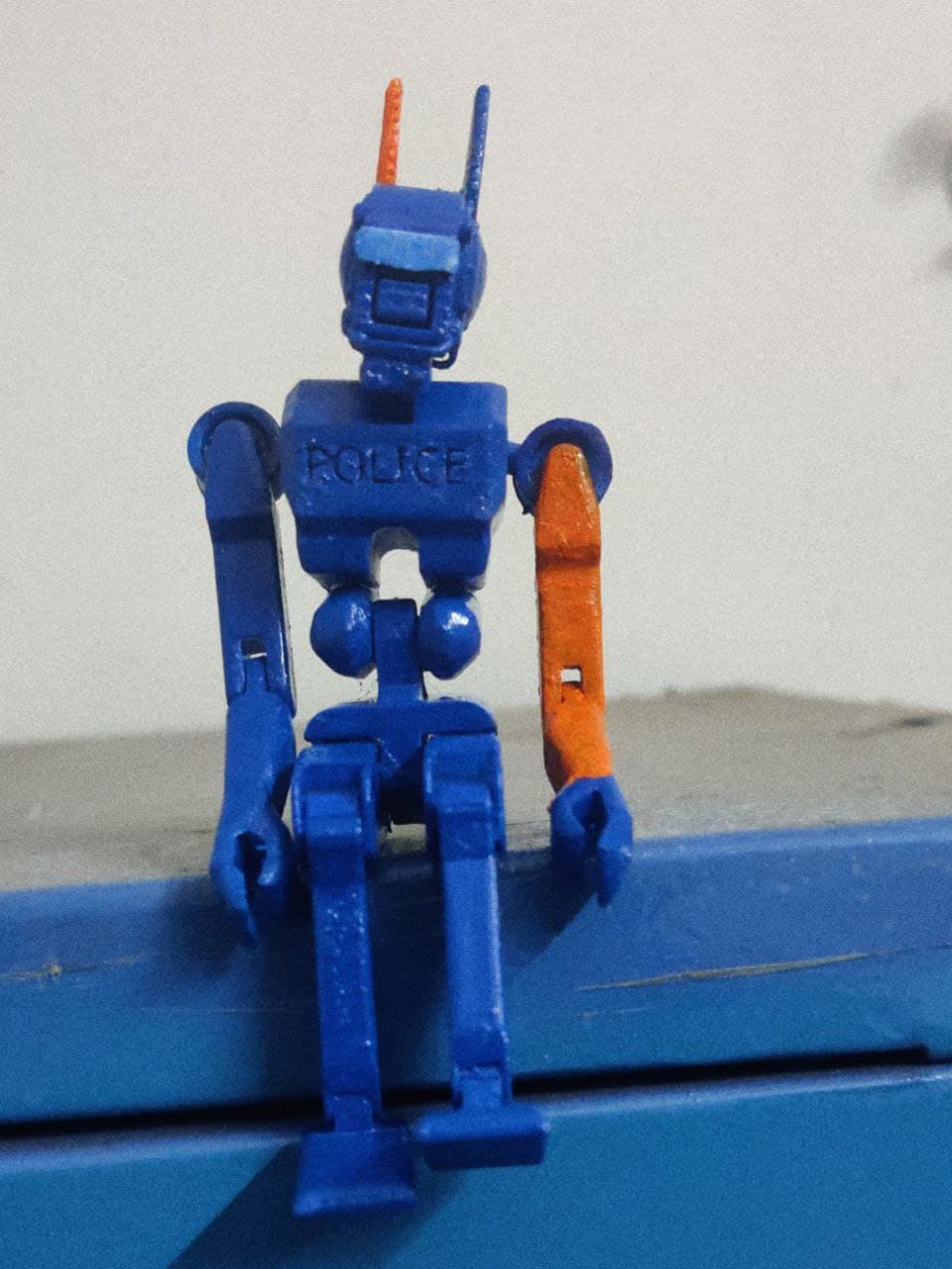
to make the model look more cooler i painted it eventhough it turned out to be a disater it was a kind of fun
for downloading file Click here
3D Scanning
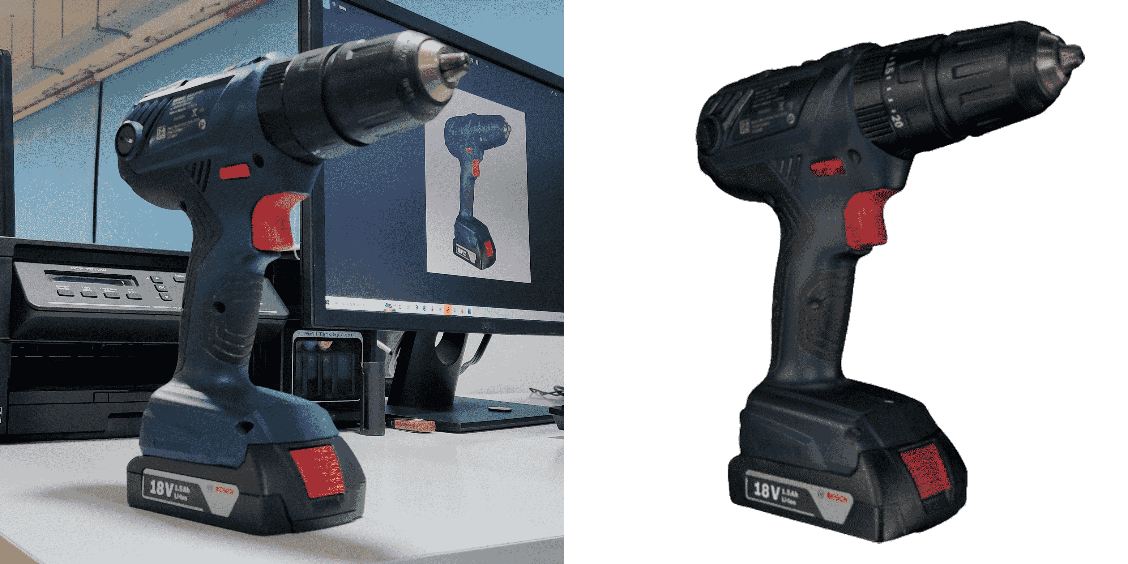
I used Artec 3D scanner which uses projected light in a pattern, usually in the form of multiple parallel beams, onto an object. By projecting a grid pattern on the object, the scanners are able to capture the deformation or distortion from multiple angles and then calculate the distance to specific points on the object using triangulation to from a 3d image of the scanned object.
Scanning
Turn on the scanner > press the NEW PROJECT (Fig.1 in slider)> Press the Red record button(Fig.3 in slider) and scan the model


Processing
Open Artec Studio and conect the scaner via DHCP server. Import the models to the studio by going to Flie > Import > Leo project (connect to scanner) (Fig.2 in slider) > Select the scaner from the poped up window (Fig.3 in slider) > Select the project (Fig.4 in slider). If the scan was quite good we can directly use Autopilot(Fig.6 in slider). configure the desired quality in Model creation window and click Next(Fig.7 in slider) > Erase unwanted mesh parts in ERASER section and click Next (Fig.9 in slider) > Now model creation will start (Fig.10 in slider) and the completed model can be exported as OBJ or STL formate by going to Flie > Export > Meshes (Fig.12 in slider). save it in desired formate.


the result of the scan is down below.
for downloading file Click here
i also used Qlone 3D Scanner I started scanning after printing a reference sheet and placing the object on top of it.

.jpg)


the result of the scan is down below