3. Computer Aided design
Objectives
- To model (raster, vector, 2D, 3D, render, animate, simulate, …) a possible final project
- To compress images and videos of this week
- and to post a description with design files to my class page
2D Designing
Vector vs raster
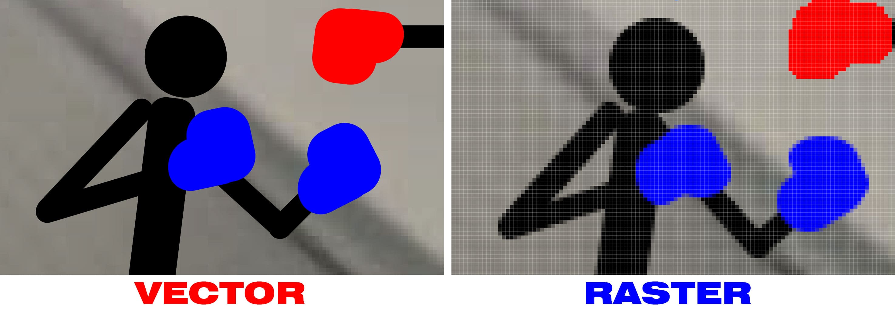
vector is a scalable image based on equations which is made up of anchoring dots connected by lines and curves. Because these visuals are not based on pixels, they are known as resolution independent, which makes them infinitely expandable.These graphics are also device-agnostic, meaning their quality is unaffected by the number of dots on a printer or the number of pixels on a screen.
whereas, Pixels, or tiny dots, are used to create raster images, which use colour and tone to create the image. when zoomed pixels appear as small squares in the image.Each image can only have a certain number of pixels; the number of pixels defines the image’s quality. This is referred to as resolution.
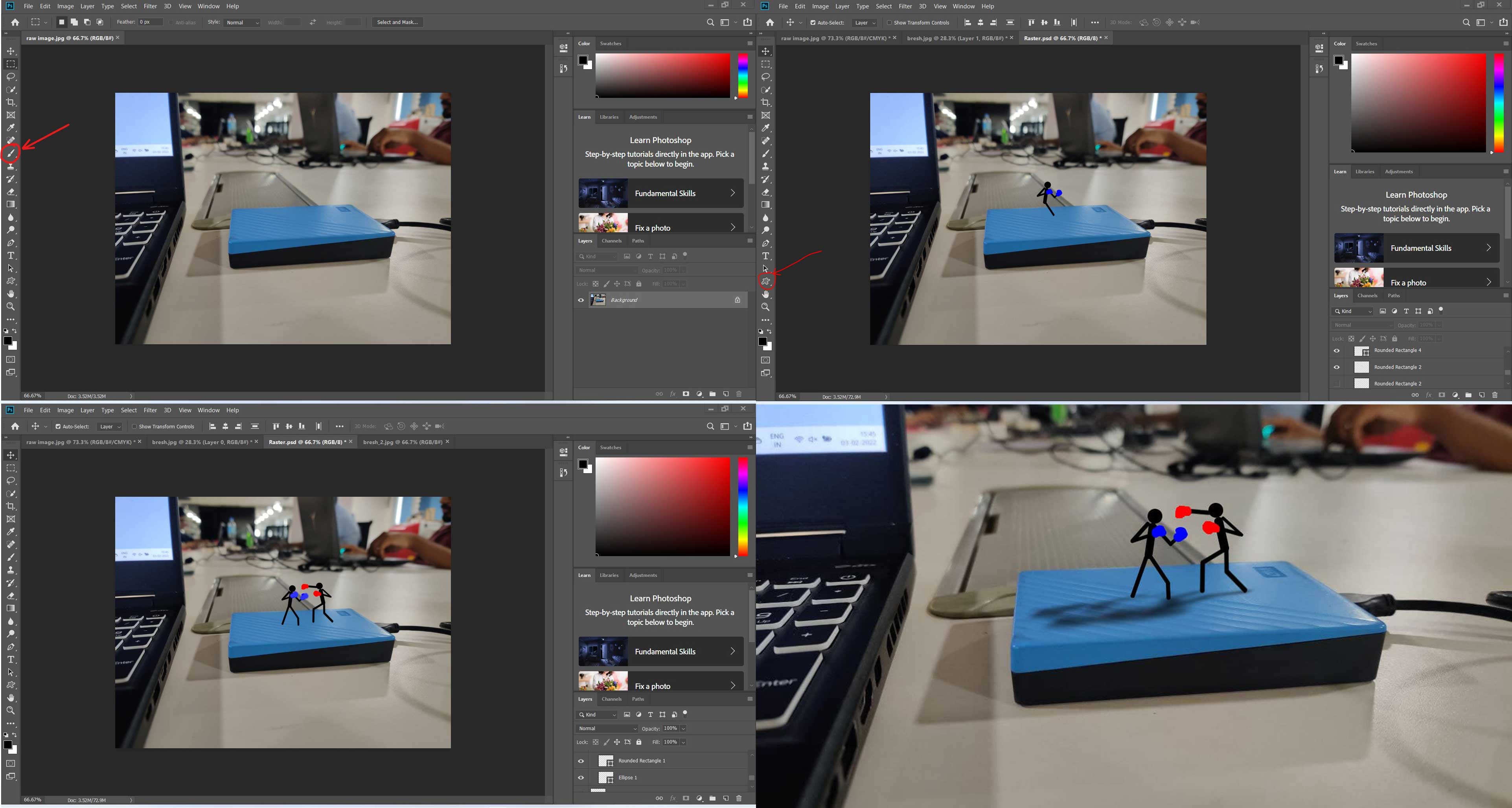
How to create a raster image
For creating raster and vector images, there is a wide range of software available. So I only experimented with creating raster and vector images in Photoshop and Illustrator to see what the differences were.
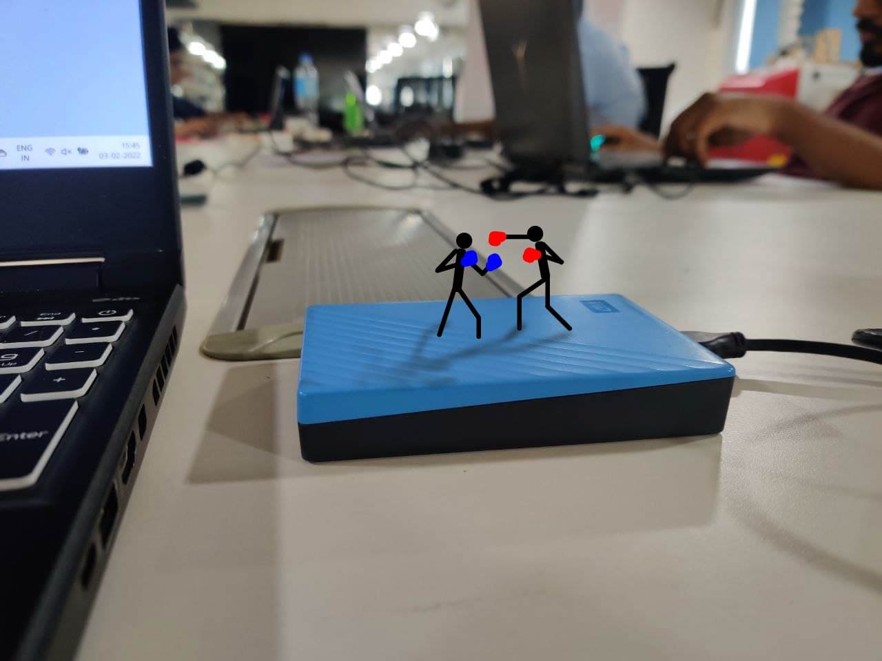
First, I took a photograph of the work desk and copied it to my computer, then I used a brush tool and rectangle tool to draw a stickman on top of the previously imported image in photoshop. And finally exported the raster image.
for downloading file Click here
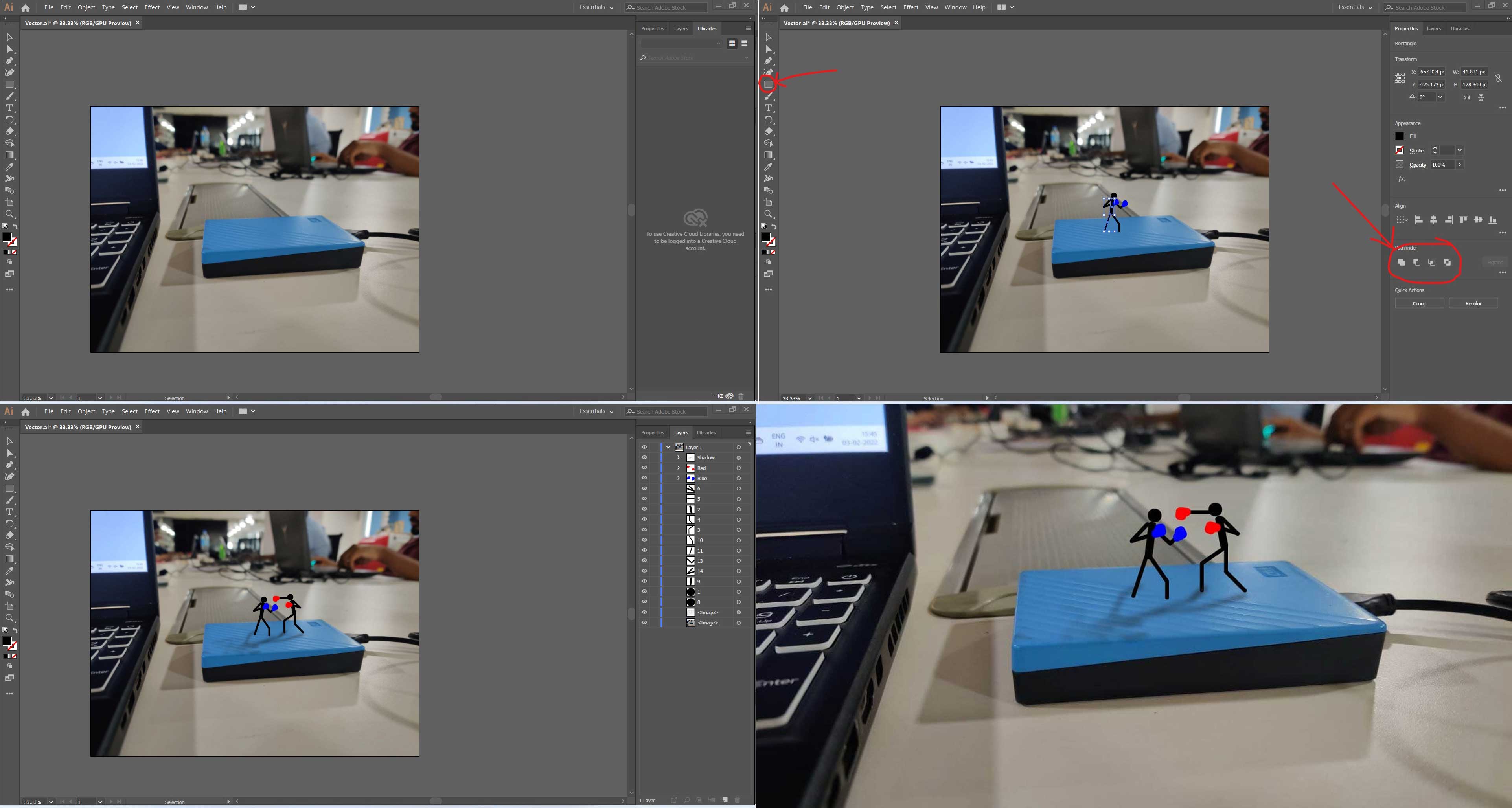
How to create a vector image
The same image was imported to Illustrator. *Note even though the image is imported to a vector software the image imported will still be in raster formate. Here I used the ellipse rectangle tool and used unio, intersection tools to draw the stick man.
for downloading file Click here
Output
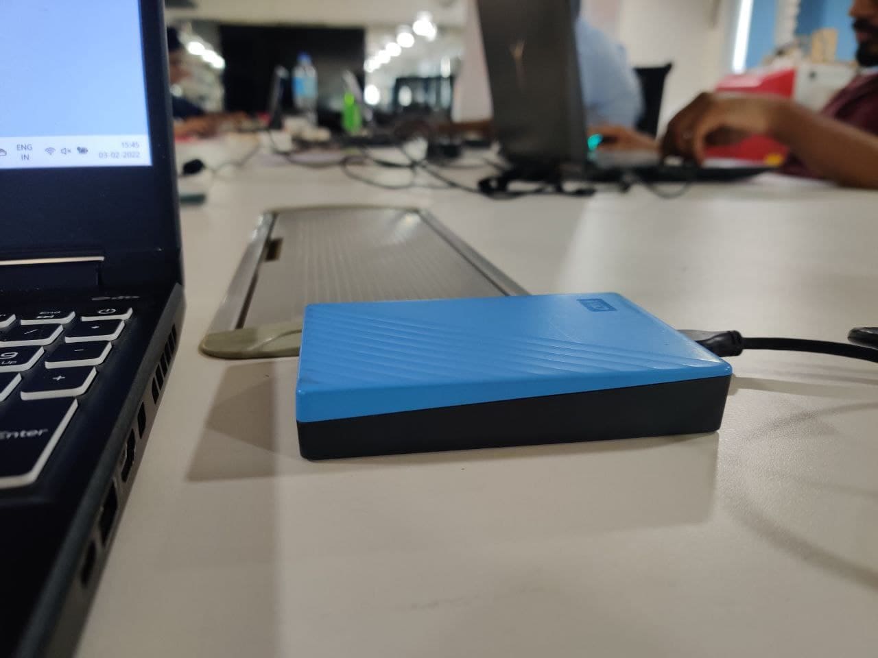
Raw Image
Raster Image
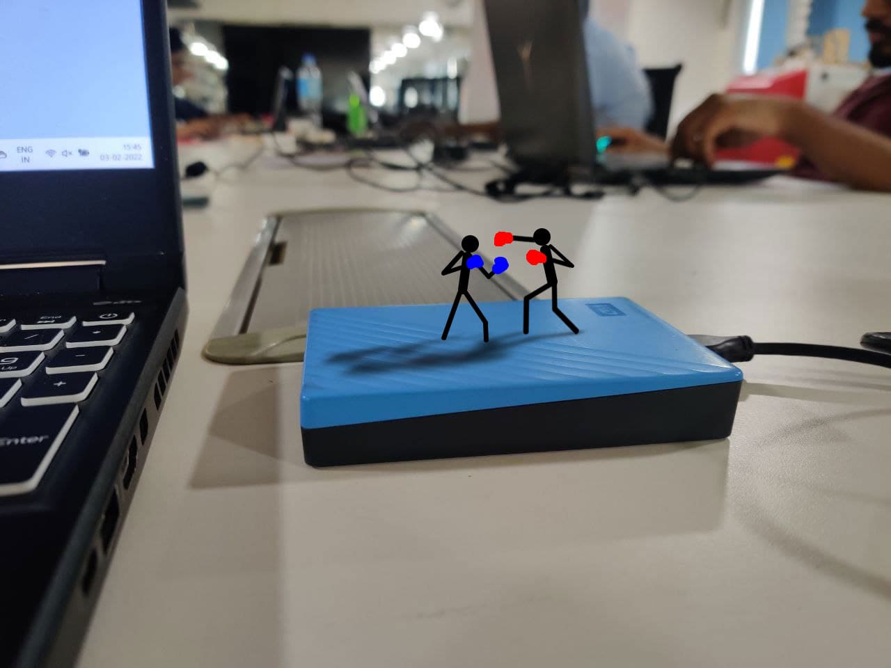
Vector Image
combarison
Priliminary designe of the Final Project
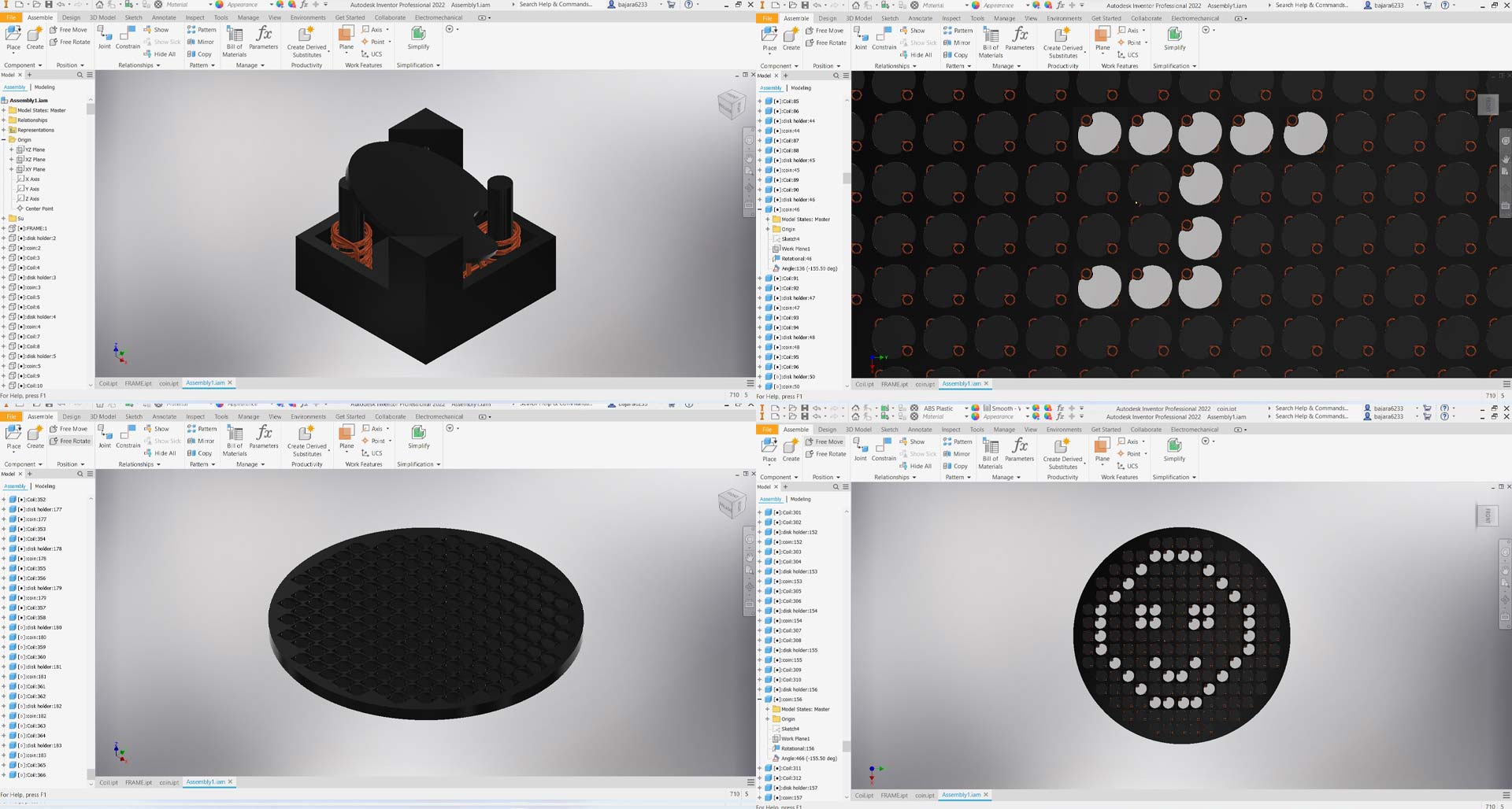
In Inventor 3D, I considered making a little animated representation of my project. I chose this software for modeling because this model has a lot of components and subassemblies, thus I thought of utilizing Autodesk inventor.
Sketching 2D
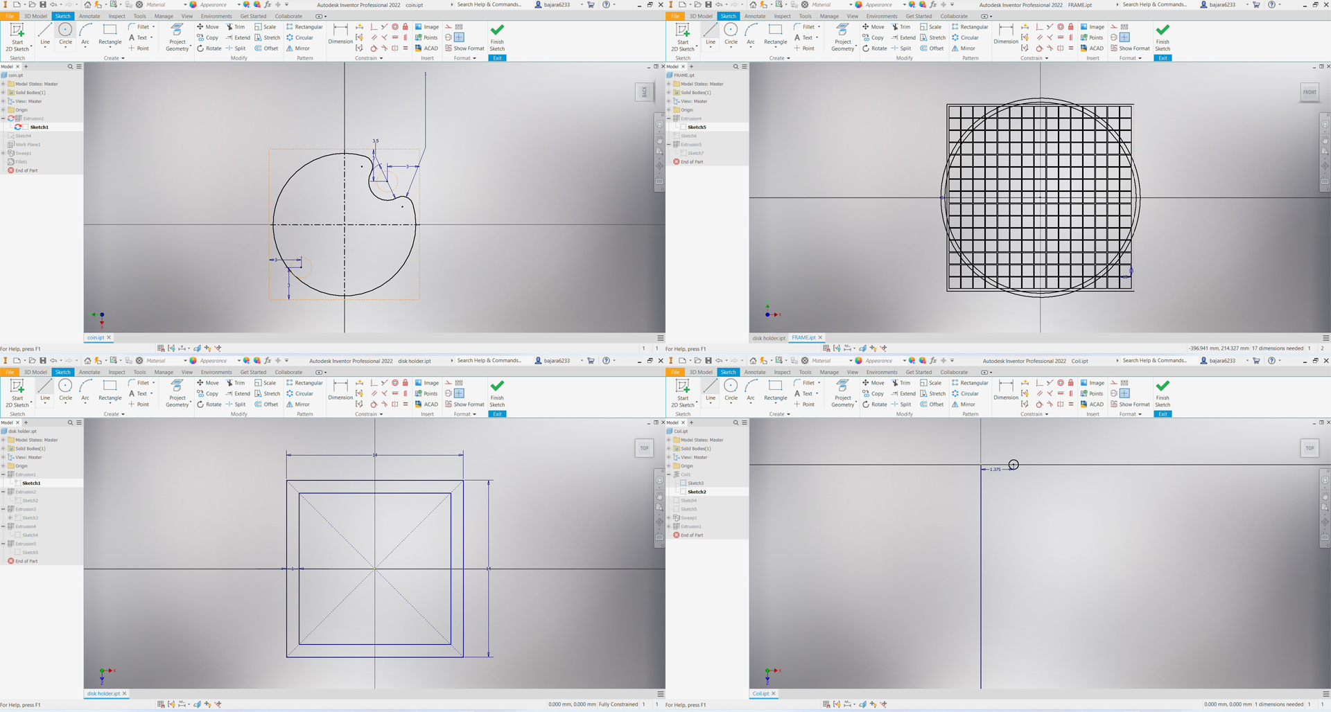
The first stage in any design is to sketch the 2D drawings, therefore I began sketching the 2D designs for individual parts.
3D Modeling
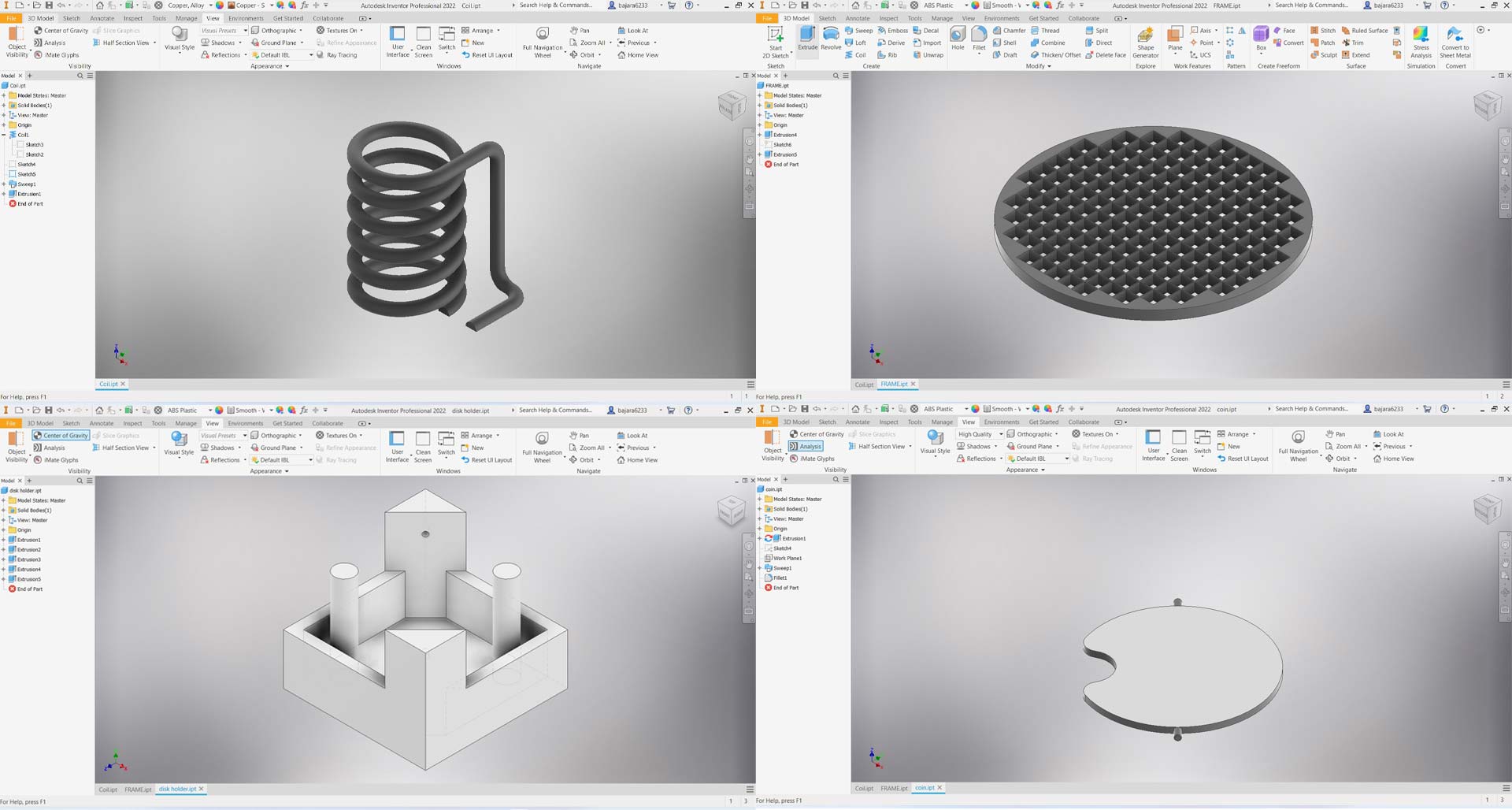
I created a 3D model of each component of my final project using basic 3D modeling tools such as extrude, sweep, coil, pattern, and others.
Assembling the model
The magnetizing coil, flip disc, and base were first assembled as a sub-assembly for the flipping mechanism. After that, the subassemblies were assembled inside the frame.
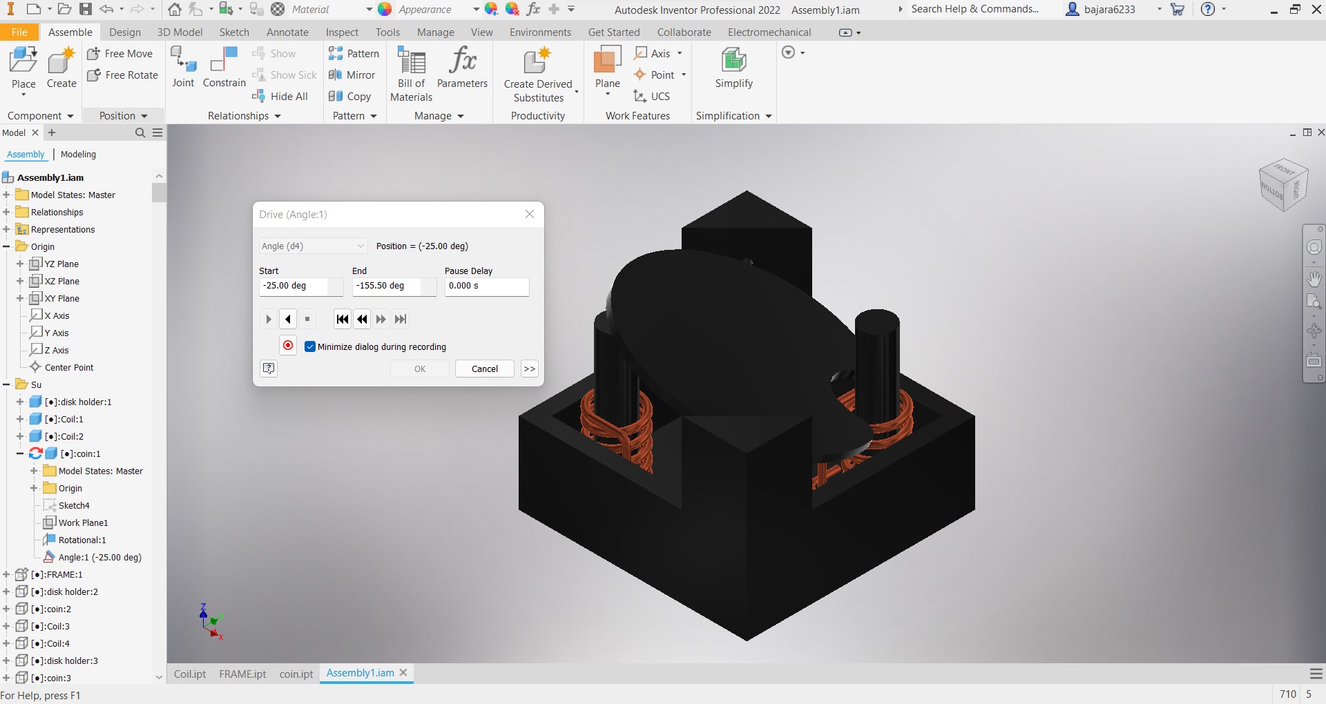
Animation/Motion Study
To animate, we must design drives for the constraint in order to control the mobility of the pieces within the assembly. As shown in the figure, click the constraint to be animated and then click on the drive to establish the drive.
Now go to environment on the top ribbon and select inventor studio
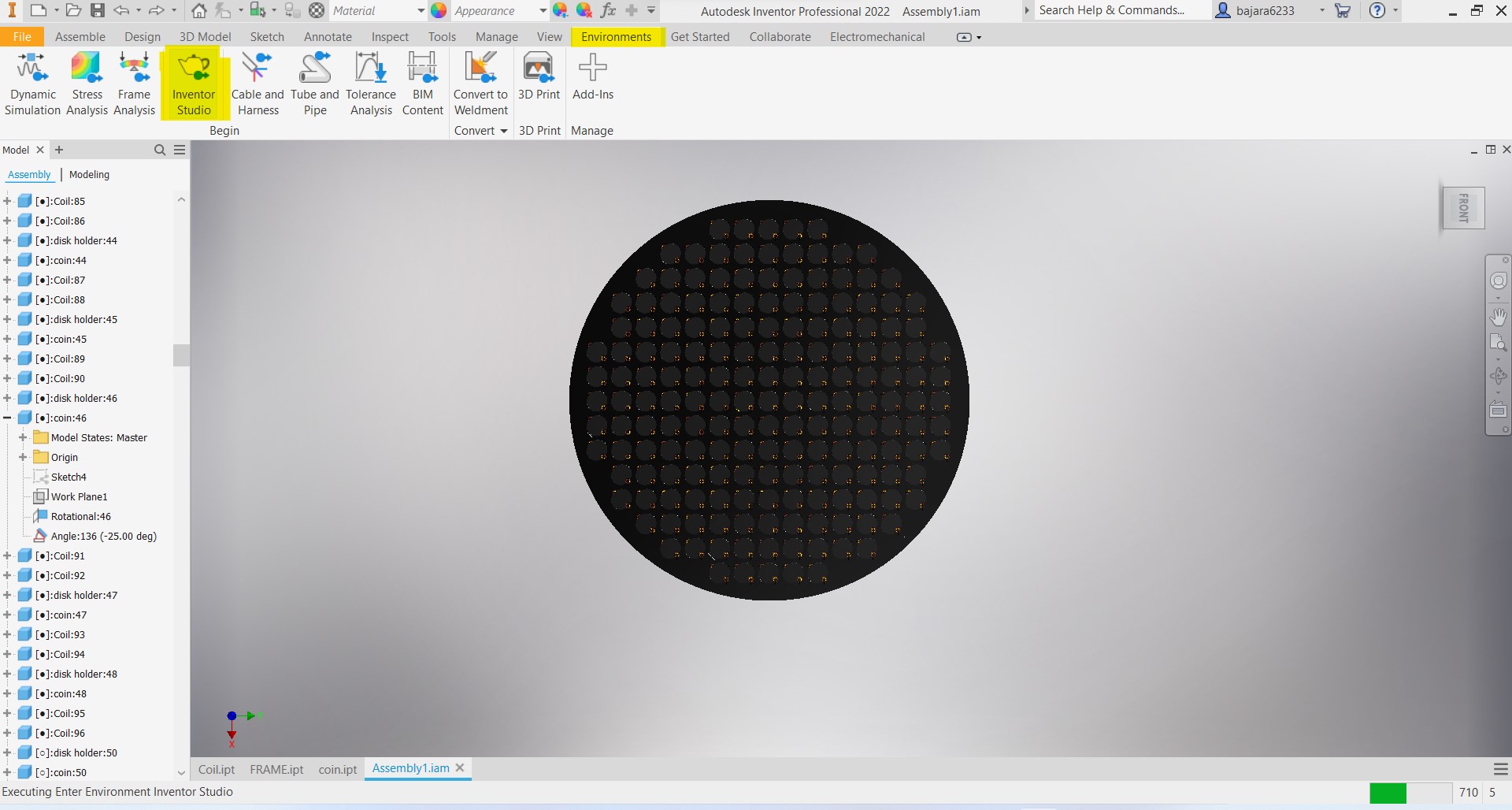
Animate the drives to achieve the desired effect.
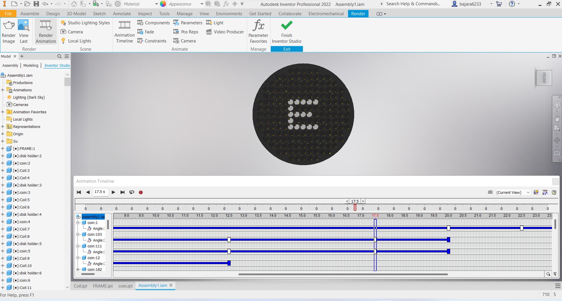
Rendering
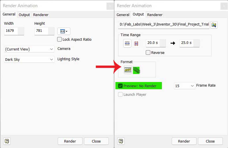
For rendering click on the render animation on the ribbon then select the following setup to get a fast rendered output.
Postproduction
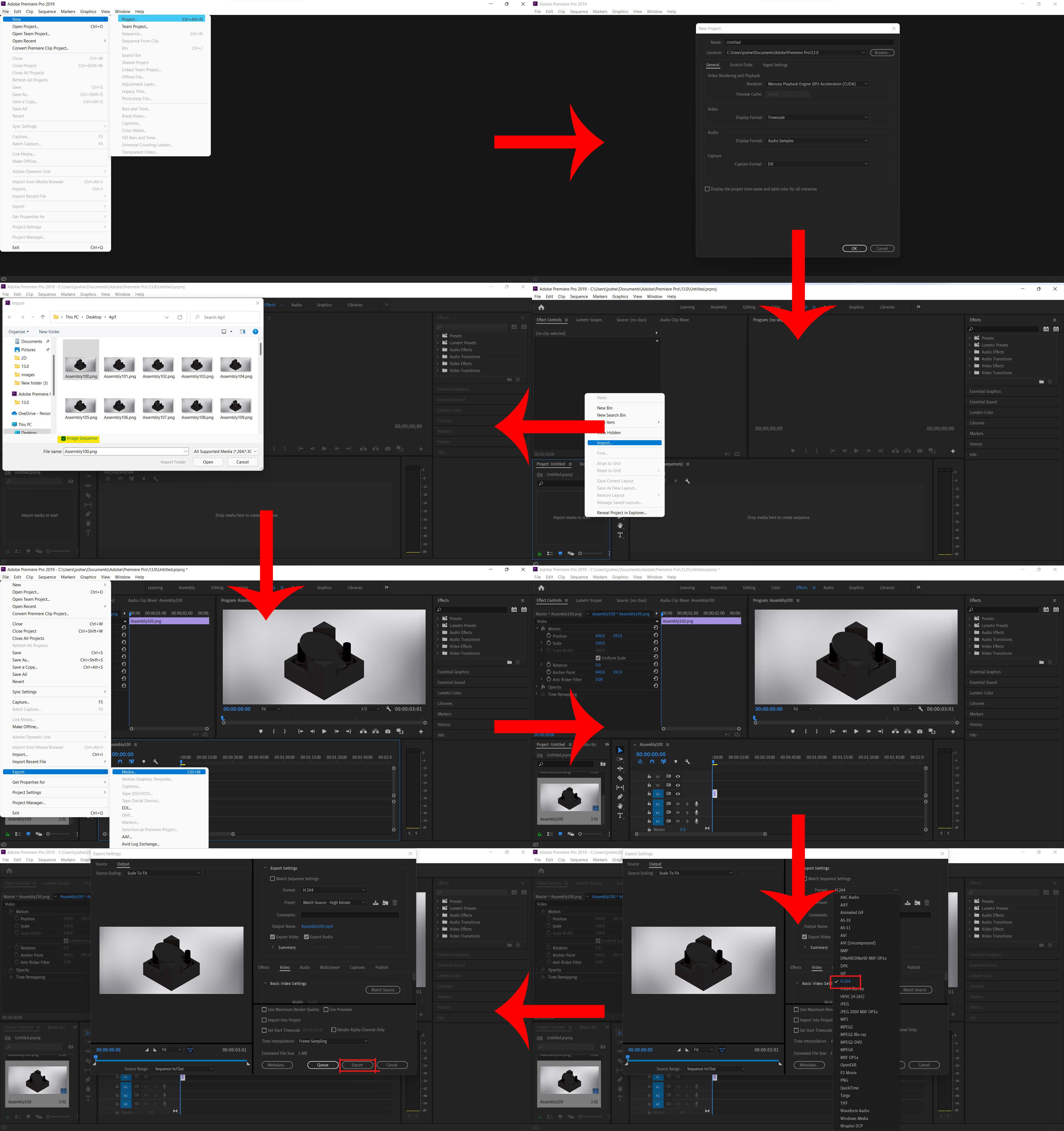
We use sequential images as output for the convenience of rendering to minimize interruptions caused by render failures, thus these files should be processed to make a video to generate the desired output. I used Adobe Premiere Pro for this purpose. import the images to the newly started project then drag it to the timeline export it in H.264 for mp4 formate
Output
for downloading file Click here
3D Designing Softwares Tryout
With prior 3D design knowledge, I experimented with Solidworks, Autodesk Inventor, Fusion 360, and Thinkercad.
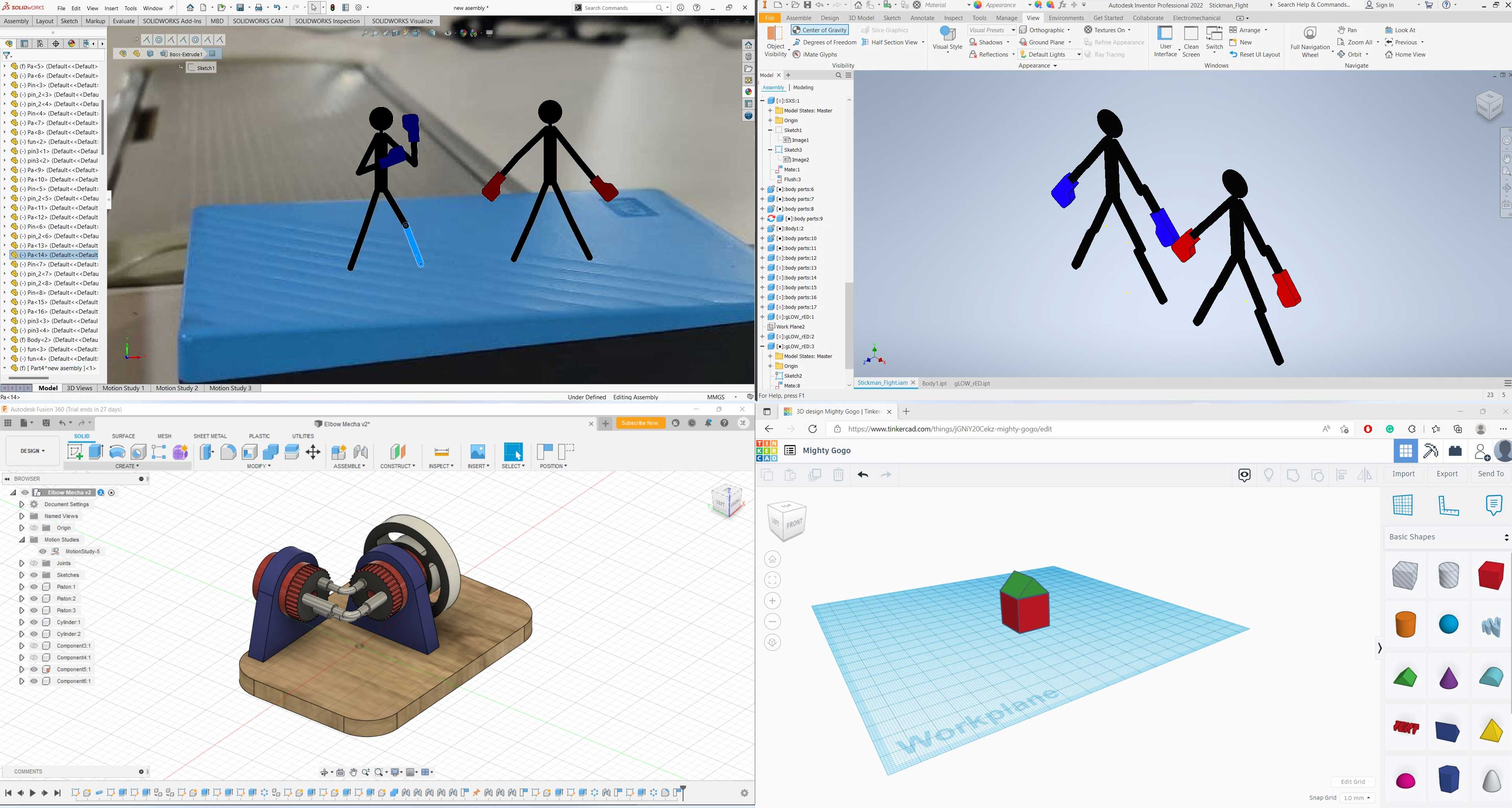 Solidworks, Autodesk Inventor, Fusion 360, Thinkercad Respectivly
for downloading solidworks file Click here
for downloading Inventor file Click here
for downloading Fusion 360 file Click here
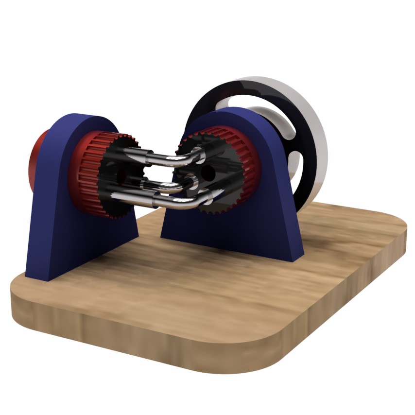
Rendering Image
Animation
Animation is rendered in lowest posible to reduce the file size.
for downloading file Click here
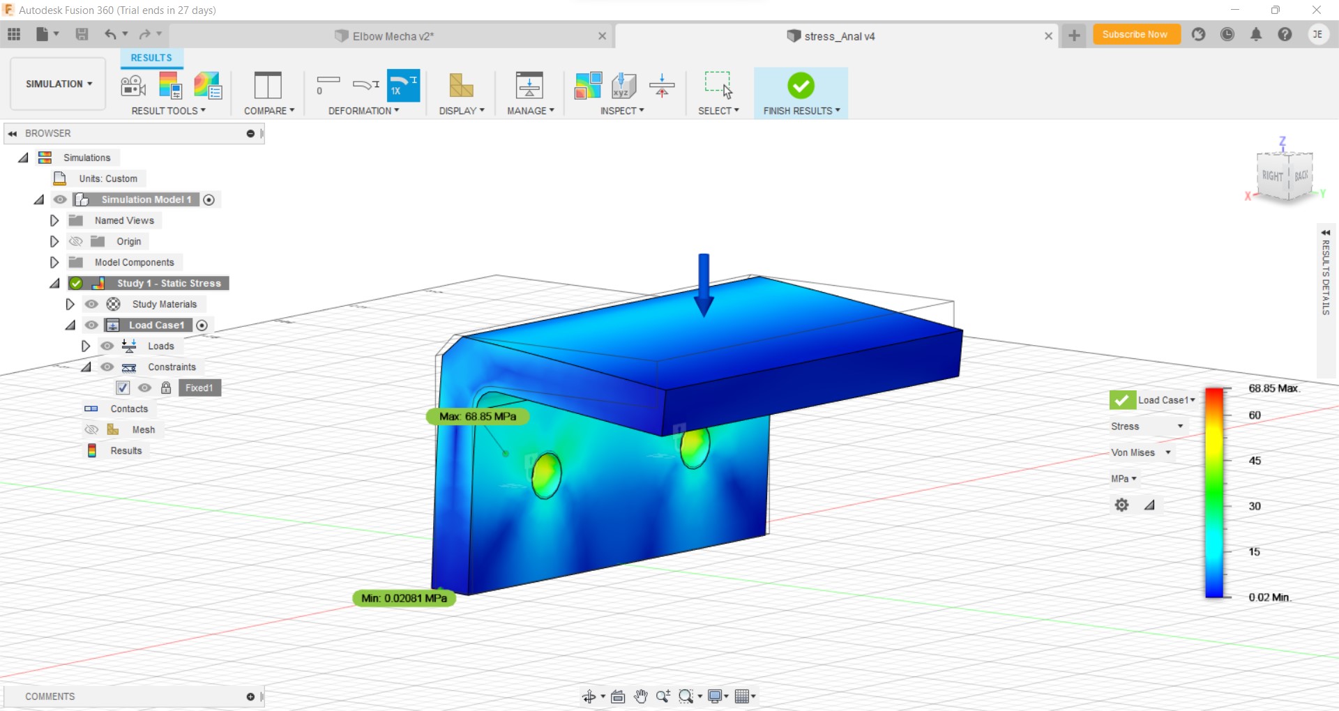
Simulation
I created a simple L shape support wich supporting a load of 1000N made of stainless steel holded on 2 bolts in fusion 360 and found out that
| Minimum | Maximum | |
|---|---|---|
| Safety Factor (Per Body) | 3.006 | 15 |
| Von Mises Stress | 0.02081 MPa | 68.85 MPa |
| Principal Stress | -26.32 MPa | 105.6 MPa |
| Normal Stress XX | -41.8 MPa | 46.26 MPa |
| Normal Stress YY | -29.52 MPa | 39.06 MPa |
| Normal Stress ZZ | -75.82 MPa | 102.6 MPa |
| Shear Stress XY | -19.44 MPa | 19.65 MPa |
| Shear Stress YZ | -27.23 MPa | 25.14 MPa |
| Shear Stress ZX | -23.52 MPa | 24.61 MPa |
| Equivalent Strain | 1.067E-07 | 0.0004229 |
| Principal Strain | 3.244E-08 | 0.0004874 |
| Normal Strain XX | -0.00009611 | 0.00009818 |
| Normal Strain YY | -0.0001293 | 0.0001352 |
| Normal Strain ZZ | -0.0002809 | 0.0003701 |
| Shear Strain XY | -0.0002406 | 0.0002433 |
| Shear Strain YZ | -0.0003372 | 0.0003113 |
| Shear Strain ZX | -0.0002913 | 0.0003047 |
for downloading file Click here
for viewing result Click here
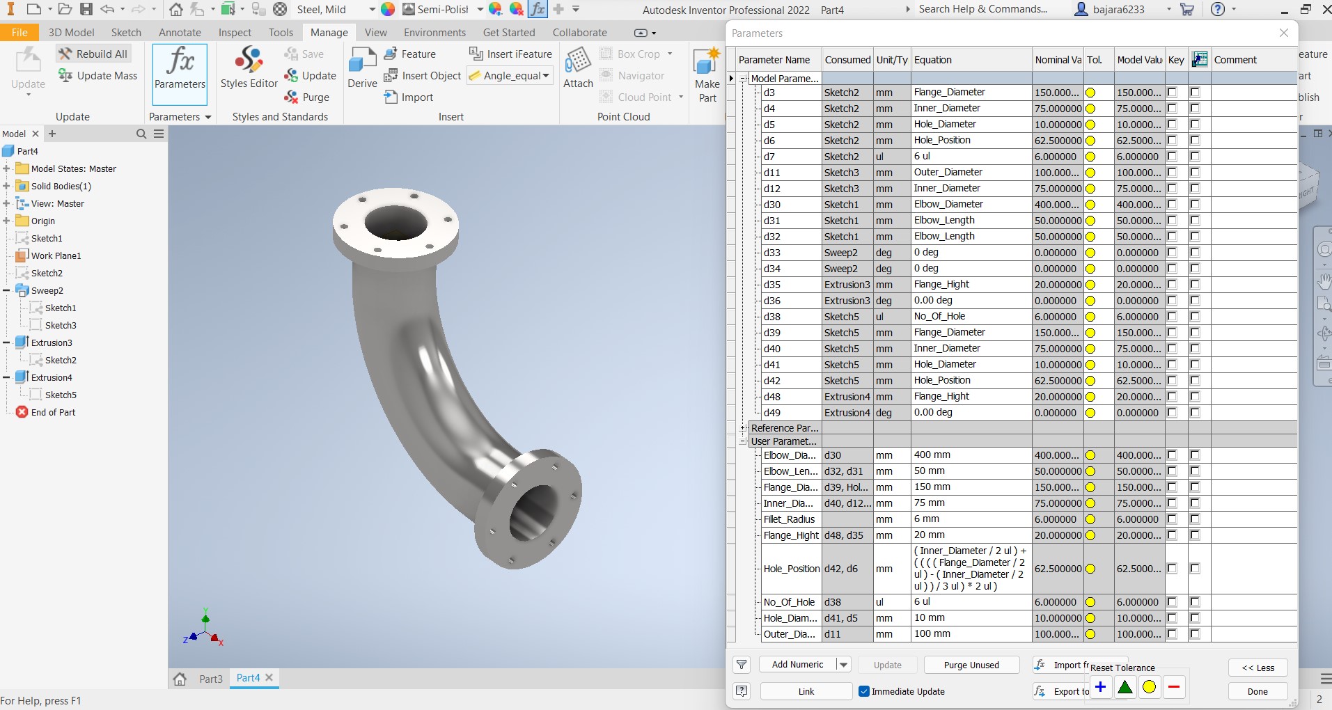
Parametric Design
As one of the most concentrated portions of the last class was Parametric Design, I tried designing one elbow pipe joint in Autodesk Inventor with pre-defined parameters.
for downloading file Click here
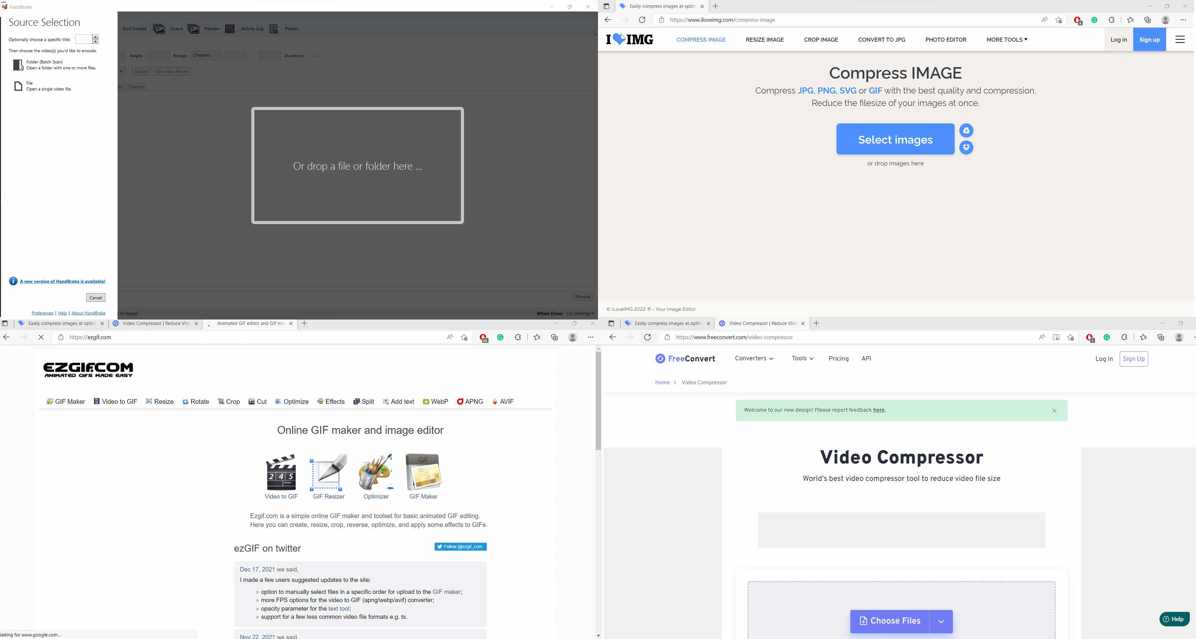
compressing images and videos
We can reduce the size of the image/video when exporting it from the respective editors by adjusting the settings to get a compressed output for further compression. I used some online tools, Links to all of the compressors are provided below. I also used Handbrake to compress video without sacrificing quality.
- https://handbrake.fr/downloads.php
- https://www.iloveimg.com/compress-image
- https://ezgif.com/
- https://www.freeconvert.com/video-compressor