7. Electronics design
Objectives
Group (To redirect to group assigment page Click here)
- use the test equipment in your lab to observe the operation iof a microcontroller circuit board
Individual
- redraw an echo hello-world board,
- adding a button and LED (with current-limiting resistor).
- check the design rules, make it, and test that it can communicate.
- extra credit: simulate its operation
PCB Designing
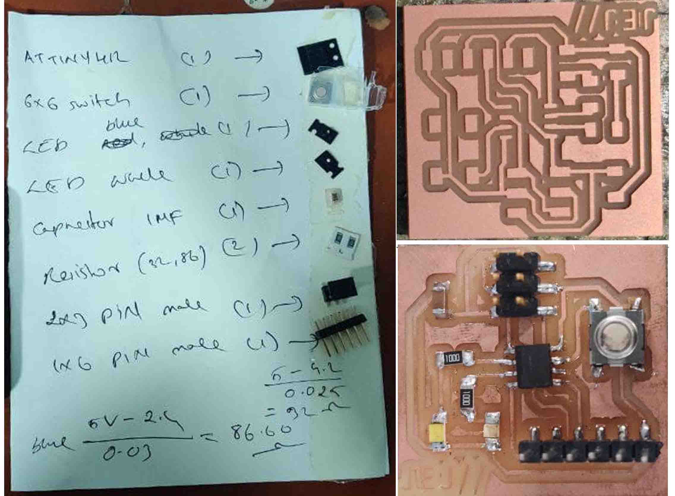
In Fusion 360, I tried doing some minor tweak to Niel’s t412-echo PCB. by integrating a push button and two LEDs.
Designing Schematics
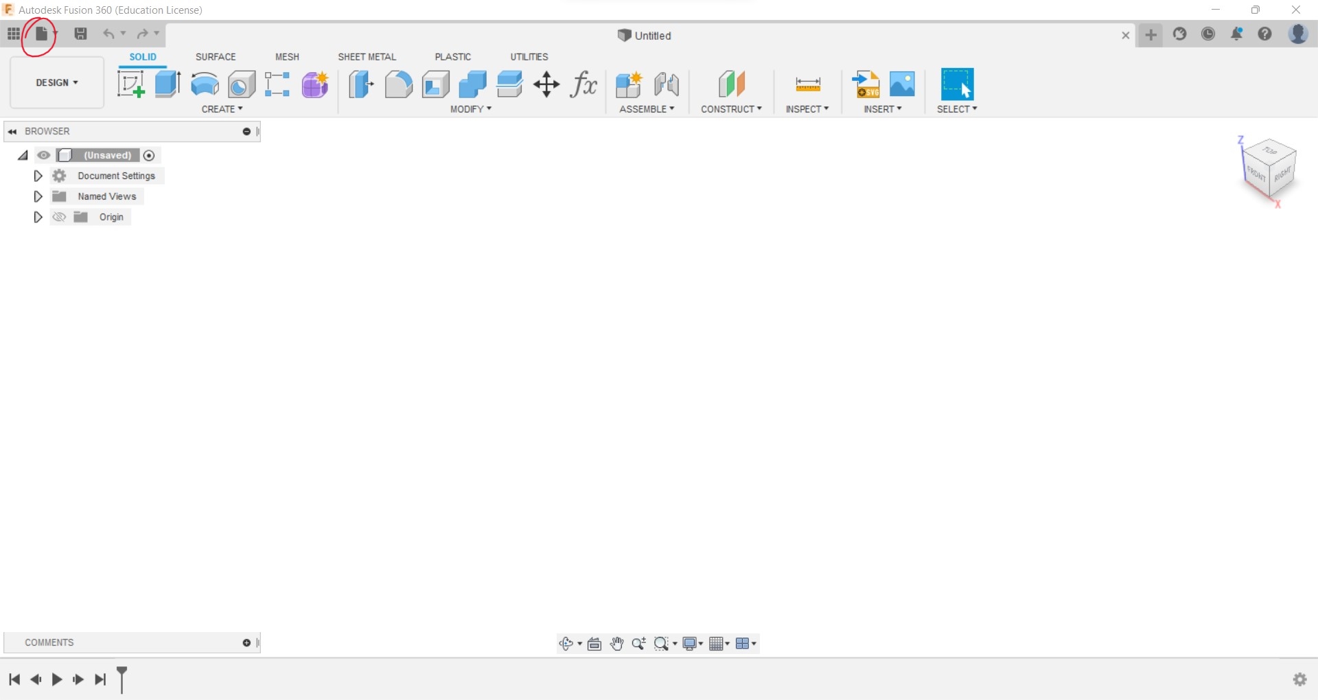
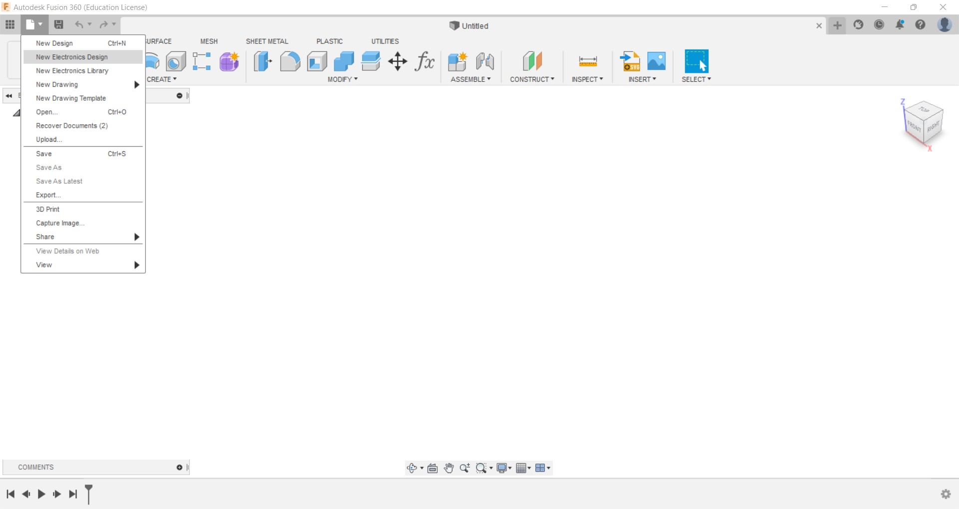
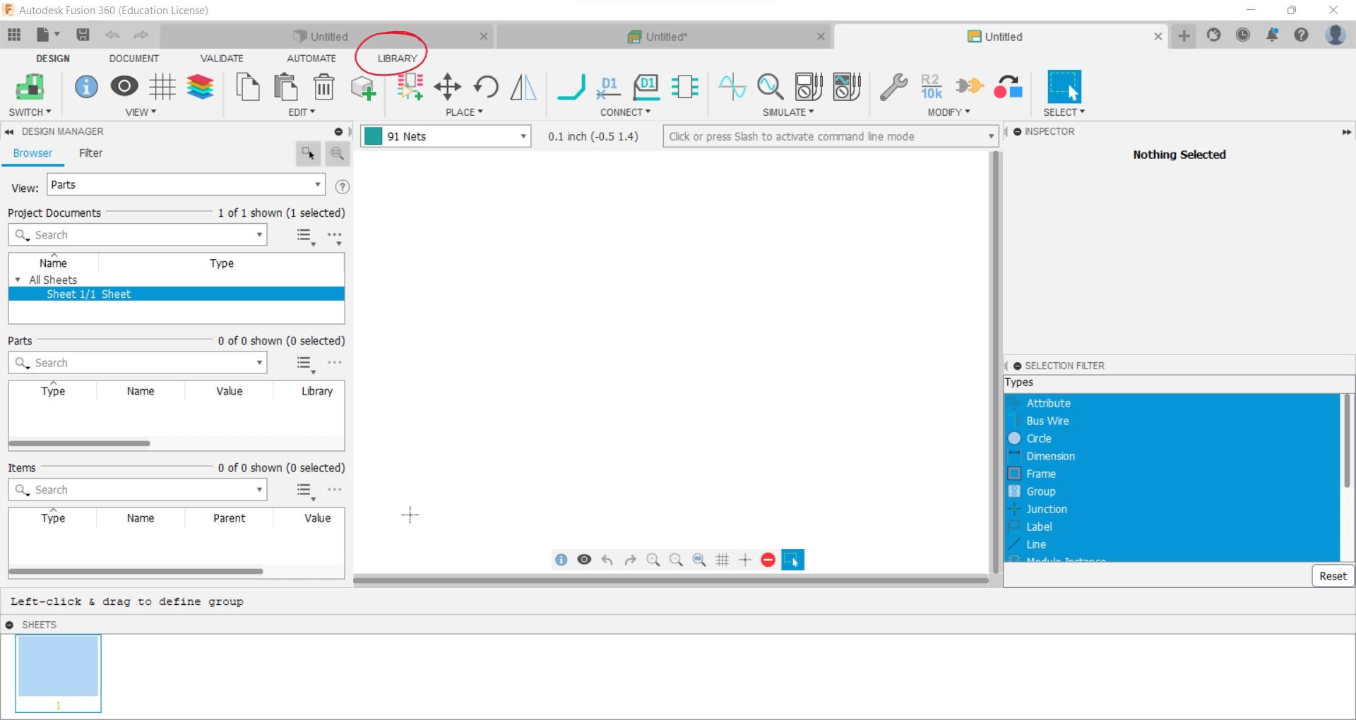
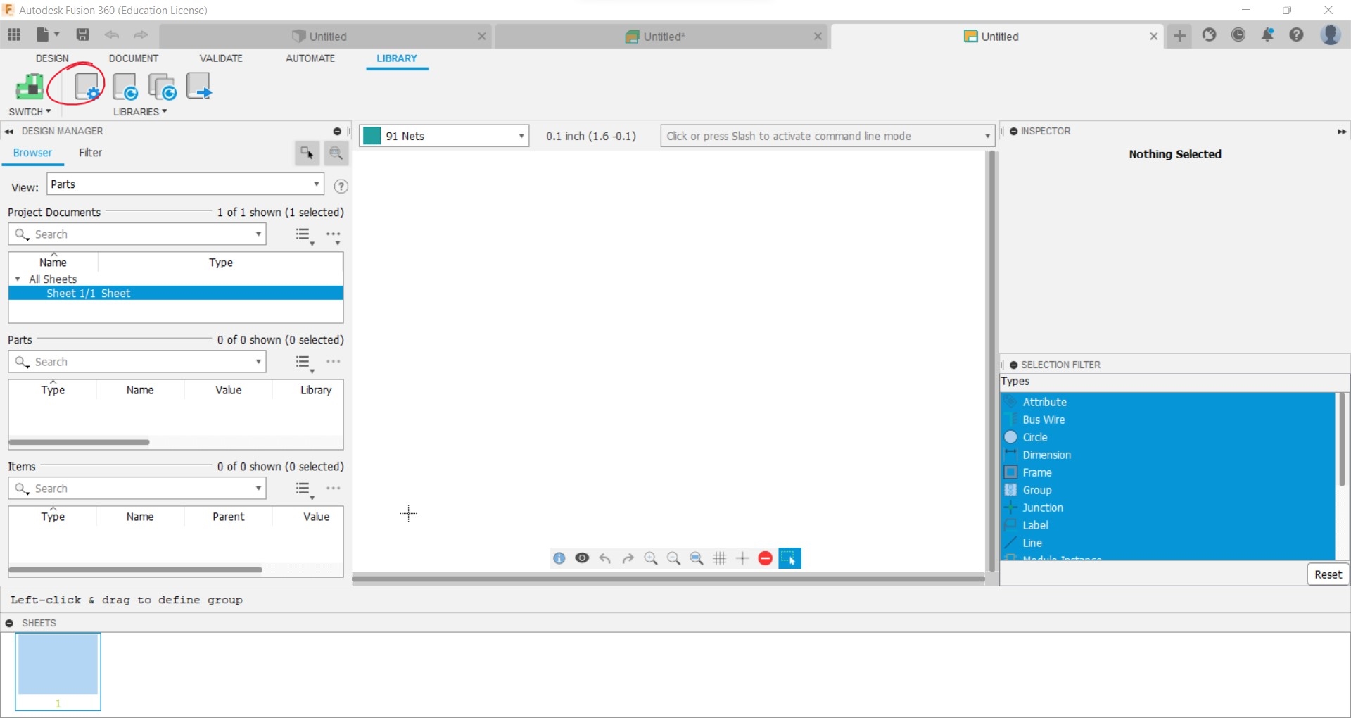
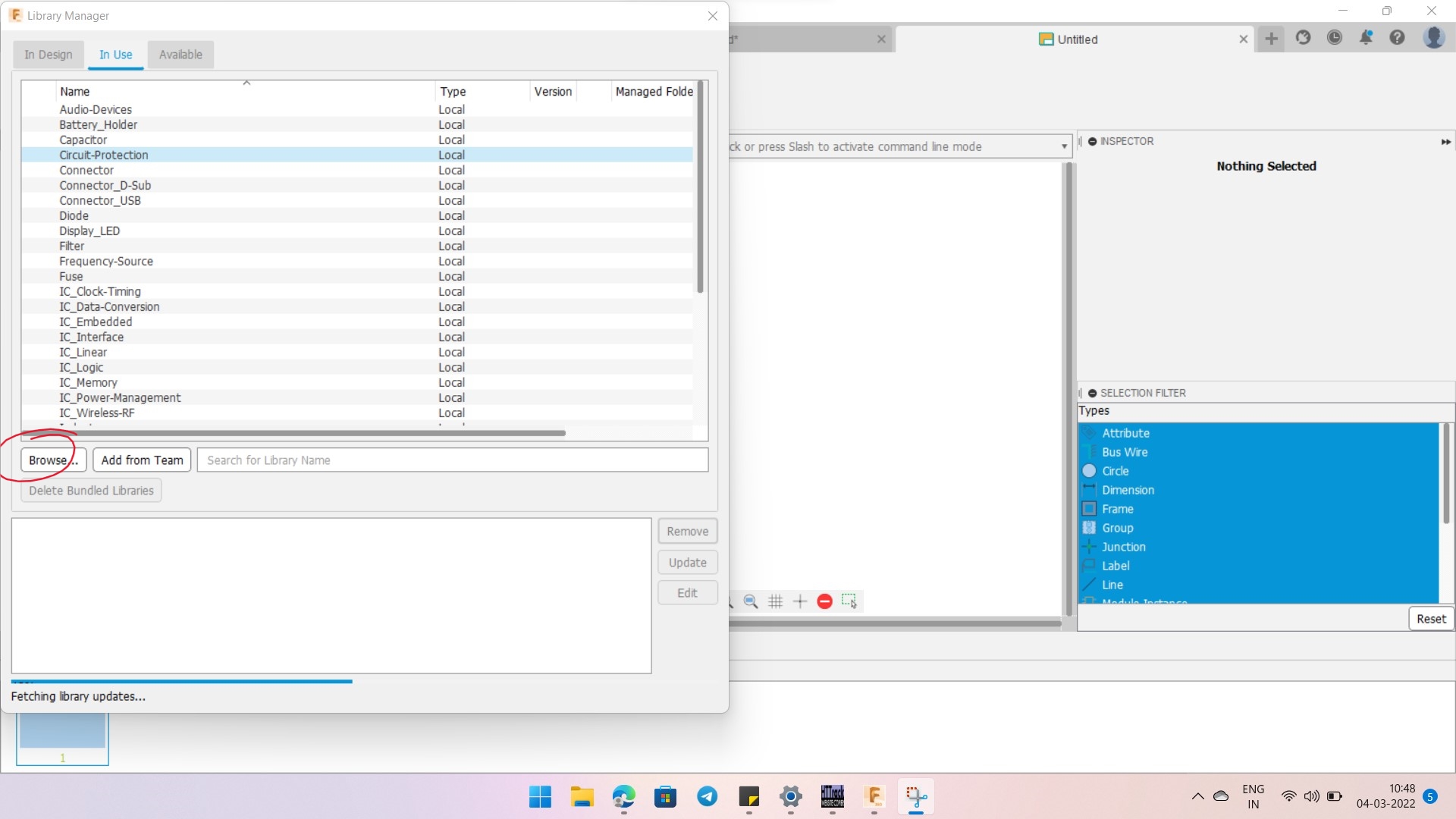
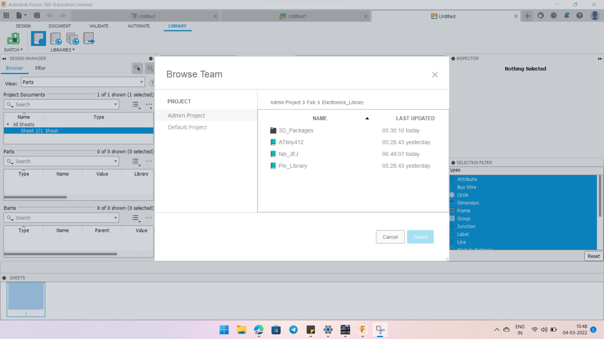
I began by selecting New Electronics Design from files in fusion, then installed the Fab component library and ATtiny-412 library from “https://gitlab.fabcloud.org/pub/libraries/electronics” and “https://app.ultralibrarian.com/” respectively . for this go to Lirary > Open Library Manager > In Use > Browse… > select the .lib file
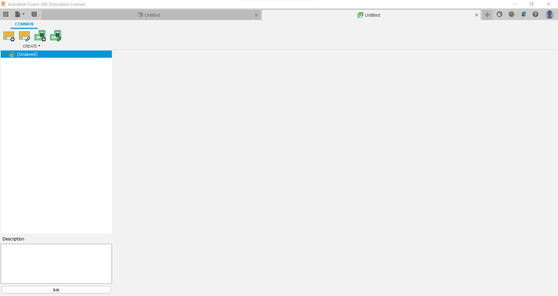
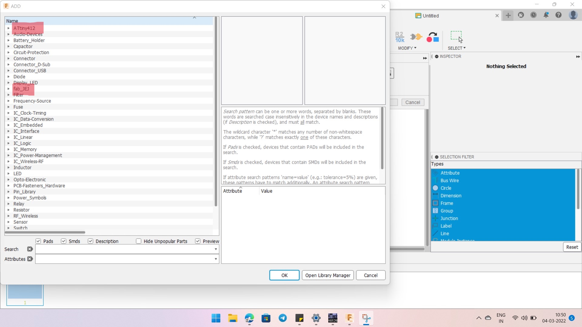
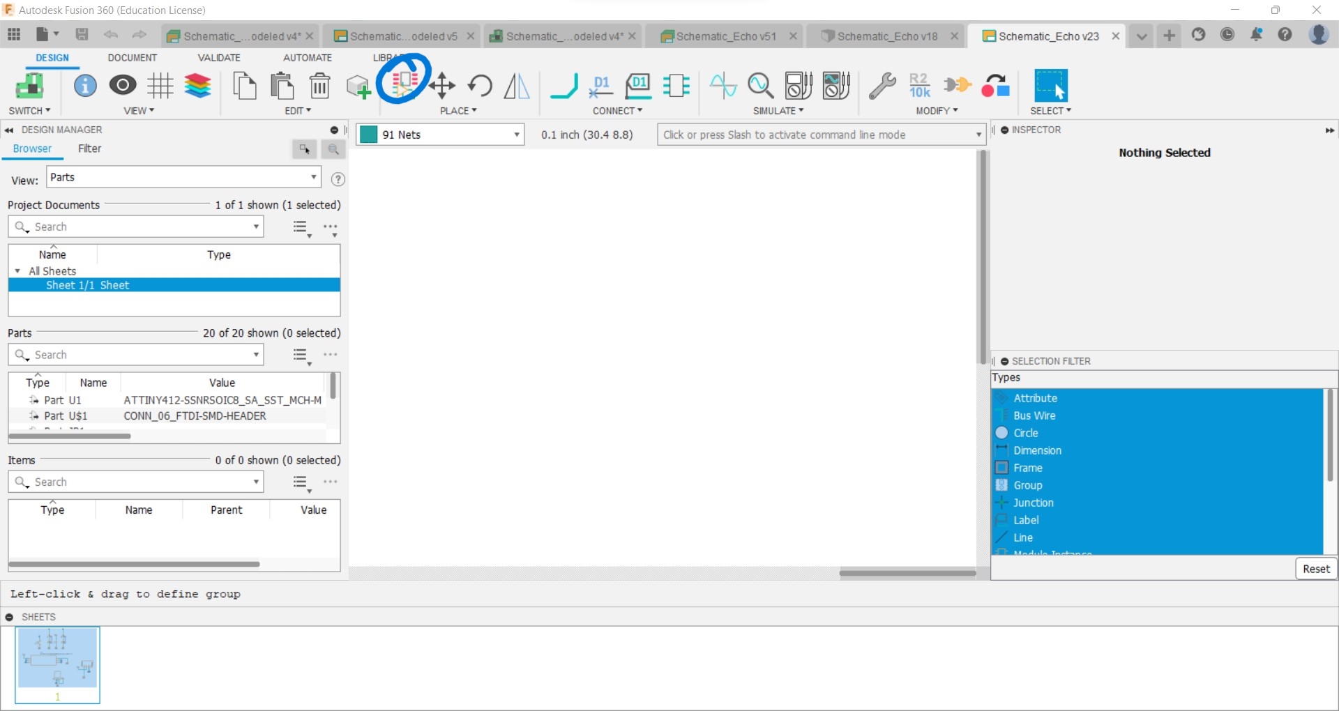
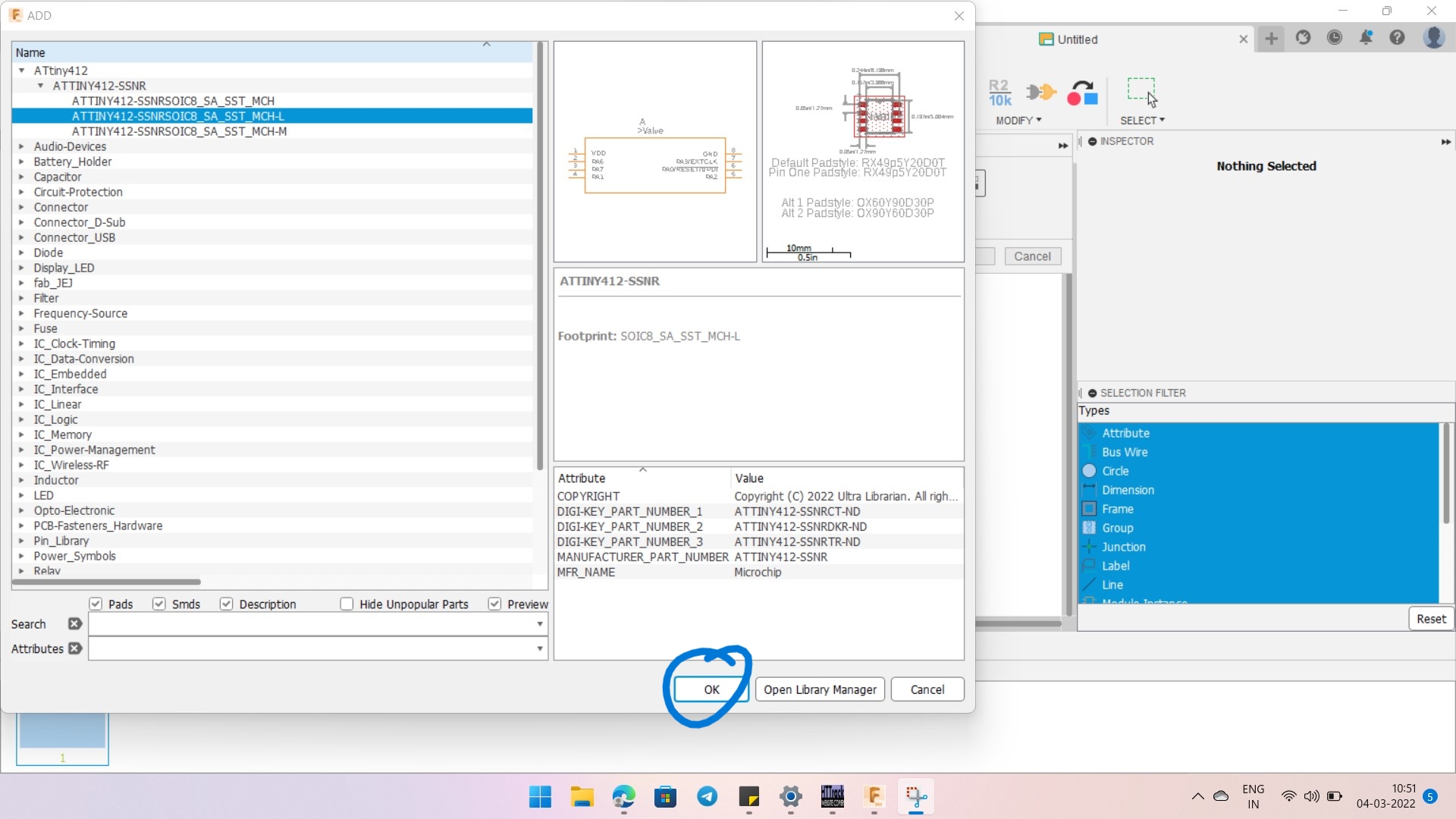
Add the needed parts in the schematic by selecting the needed part from Add parts in the Design Ribbon.
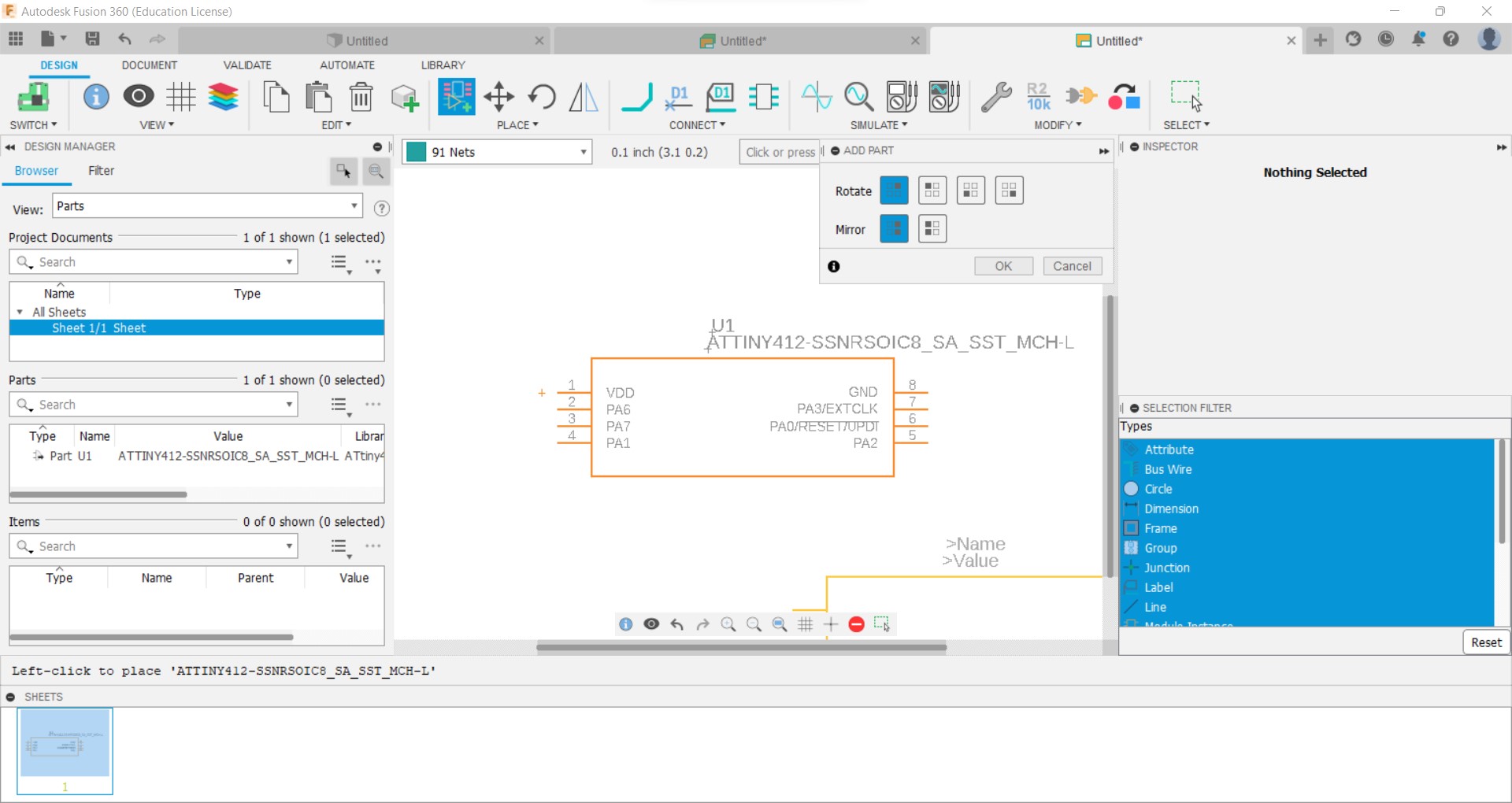
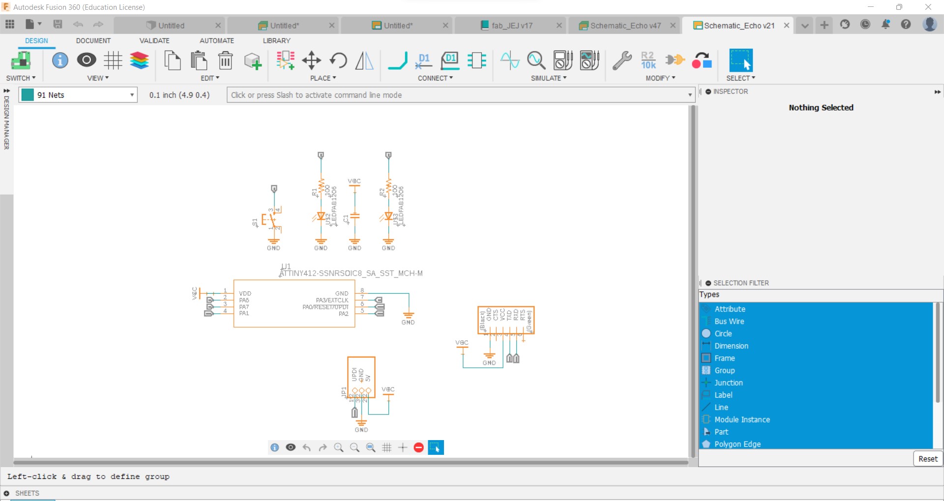
after adding all the needed parts we can we can draw nets to connect the parts. to make the schematics.
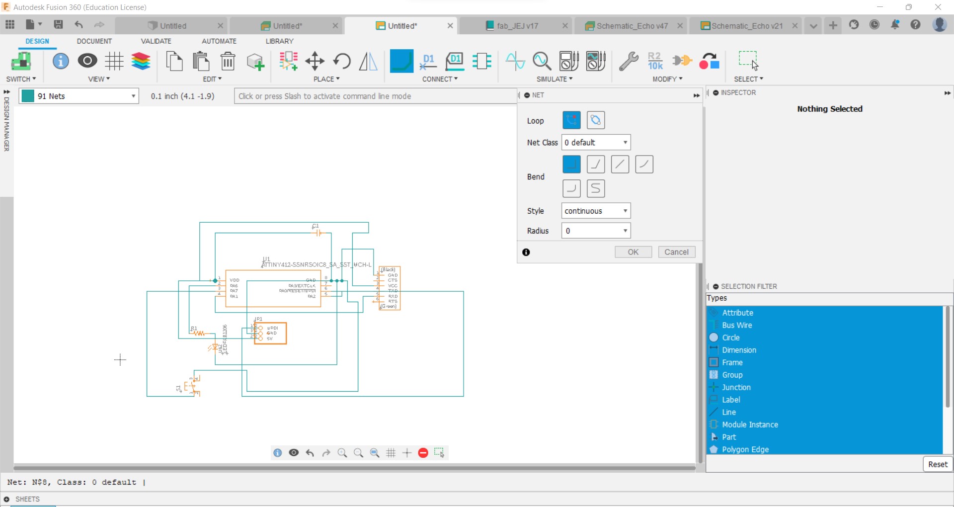
I rearranged and organized the schematic using labels and Vcc and ground symbol
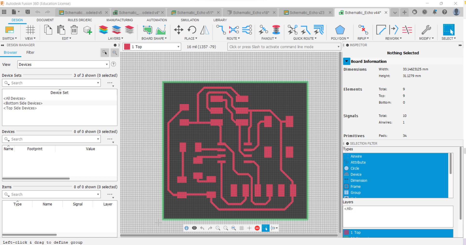
Designing PCB
Click on Switch to PCB Document from the top ribbon.
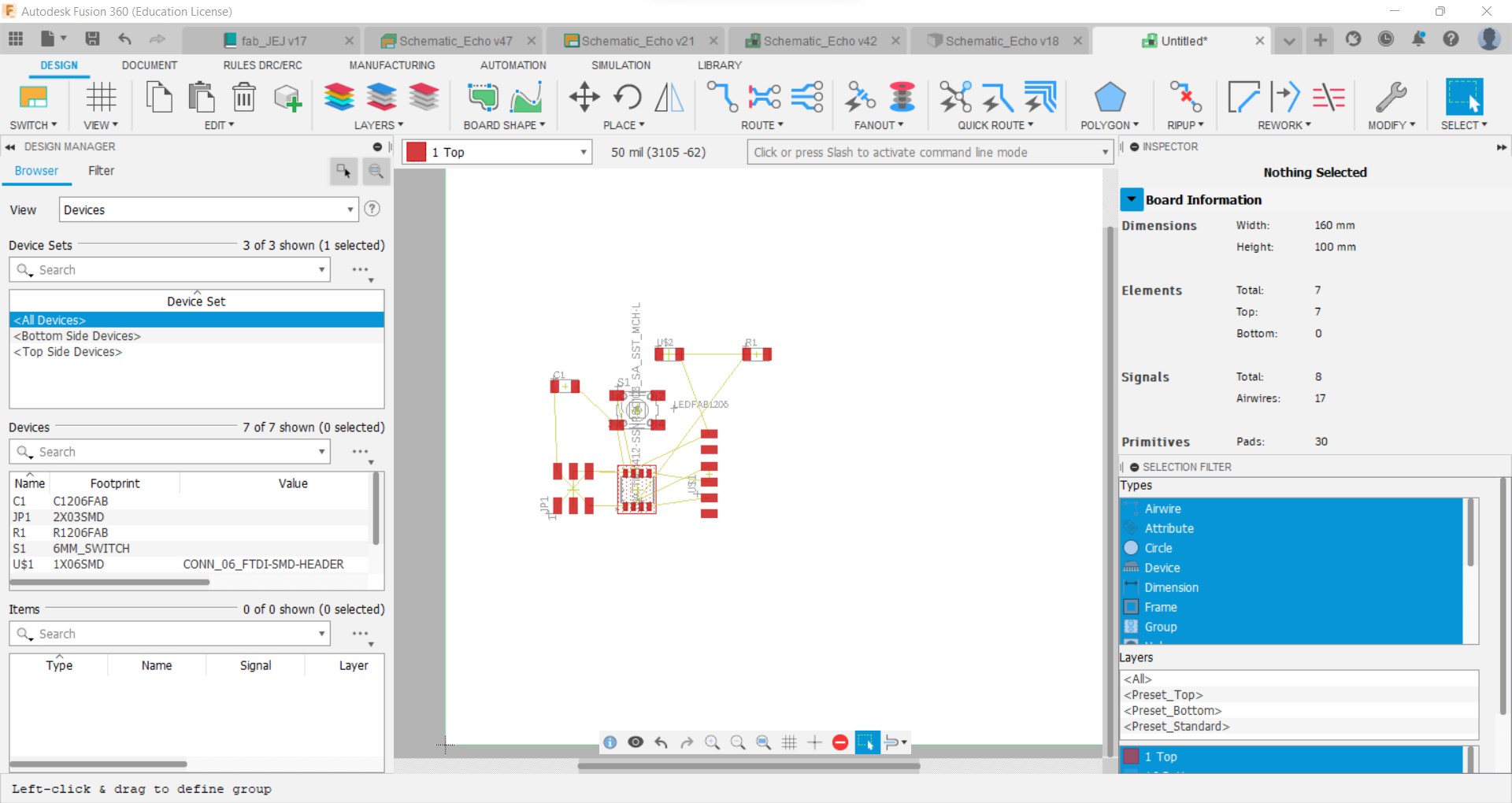
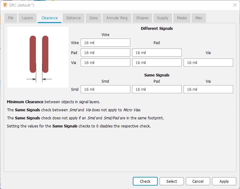
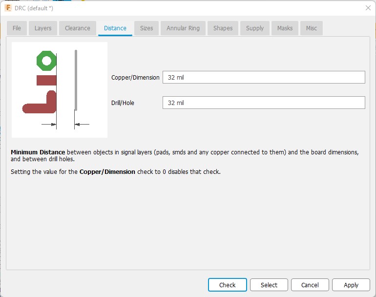
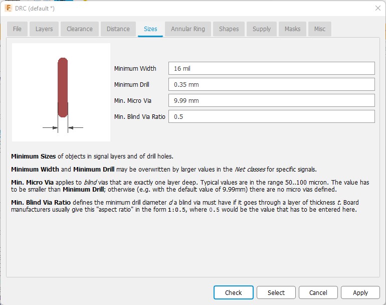
Place the components in place and set the design rules by clicking on the DRC under RULES DRC/ERC in top ribbon. The bit we us for milling is 1/64 bit. So here the trace will come around 16 mil. All clearance were set to 16 mil, Drill holes to 32 mill as we use 1/32 bit.
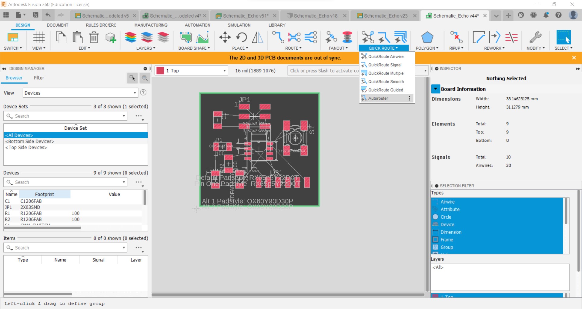
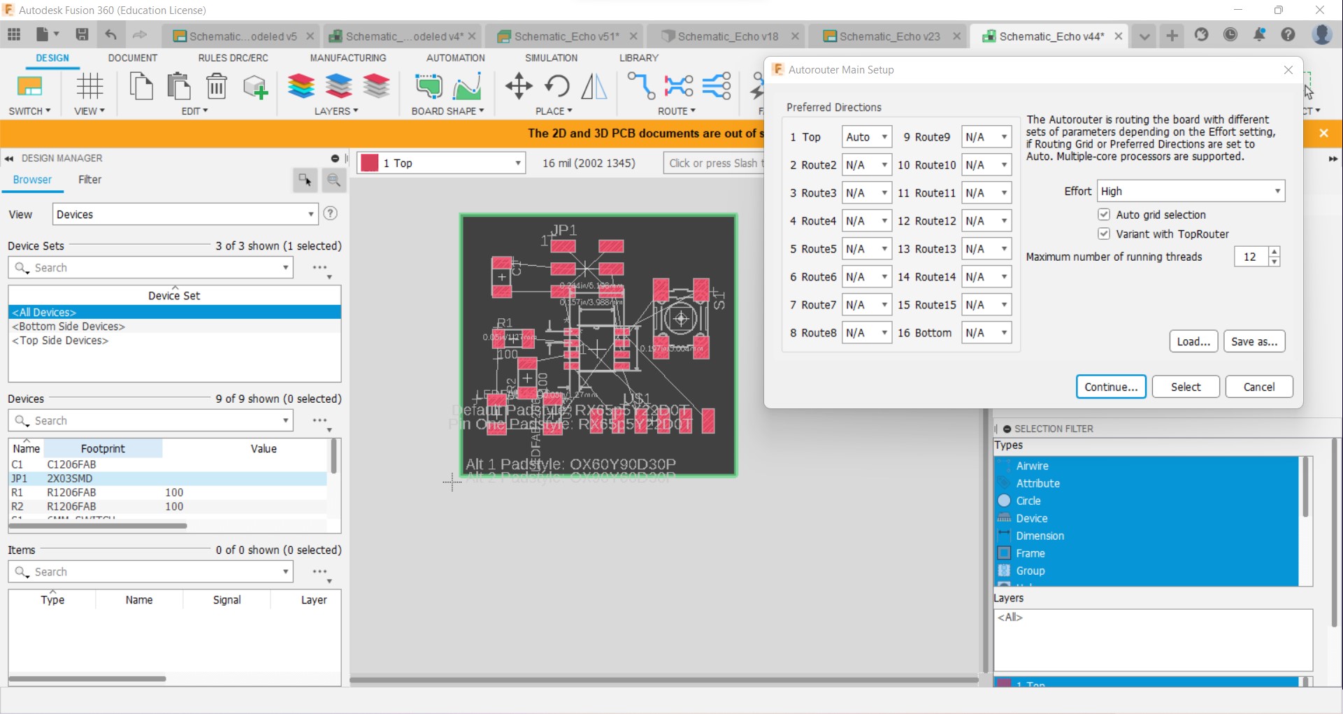
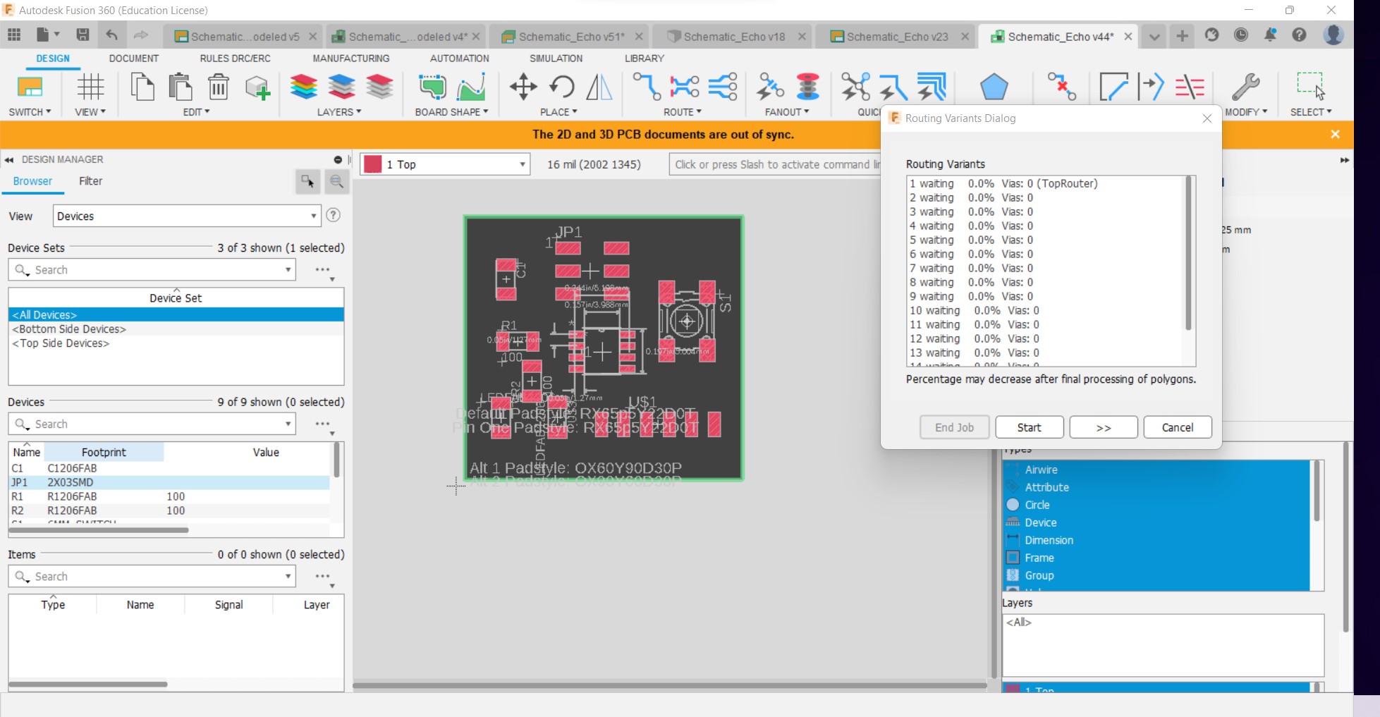
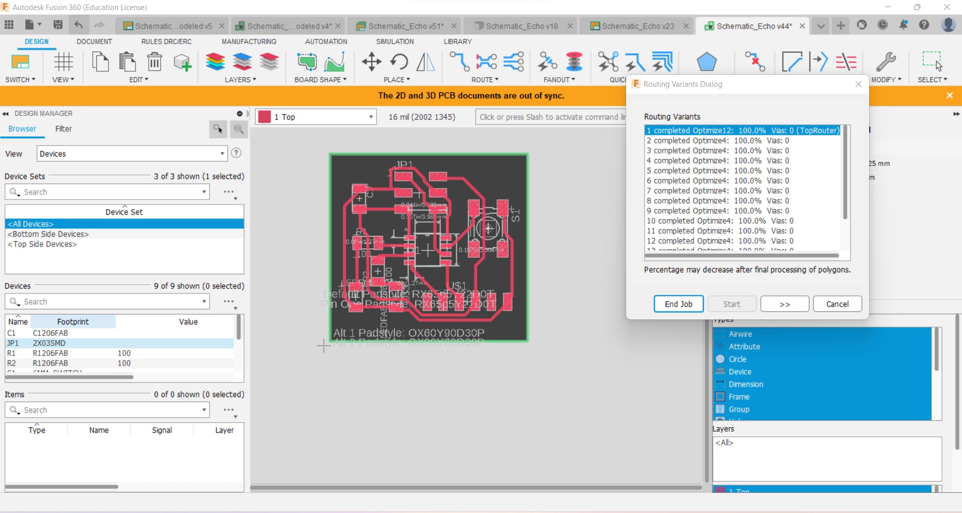
In the quick route from the top ribbon, I used Autoroute. Autoroute will give us with a number of options from which we can select the best route for us possibly 100%.
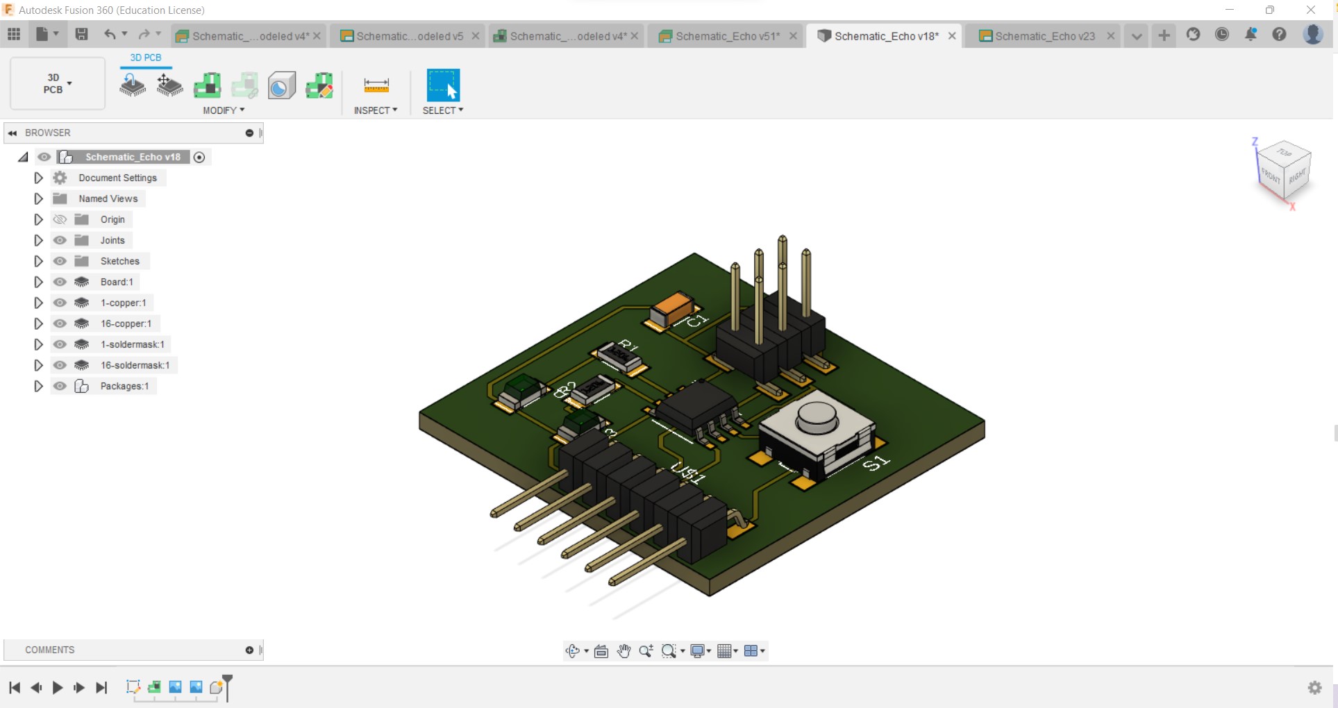
3D Model Generating
Exporting Foot Print
Type the command
export
then select location tick monochrome and set dpi to export.
the file pcb footprint which was exported was milled using MODs

for downloading file Click here
Milling and Soldering
We had seen how to solder and mill PCBs in the previous weeks. After milling, I collected the components from the inventory and soldered them on the board.
Testing Communication
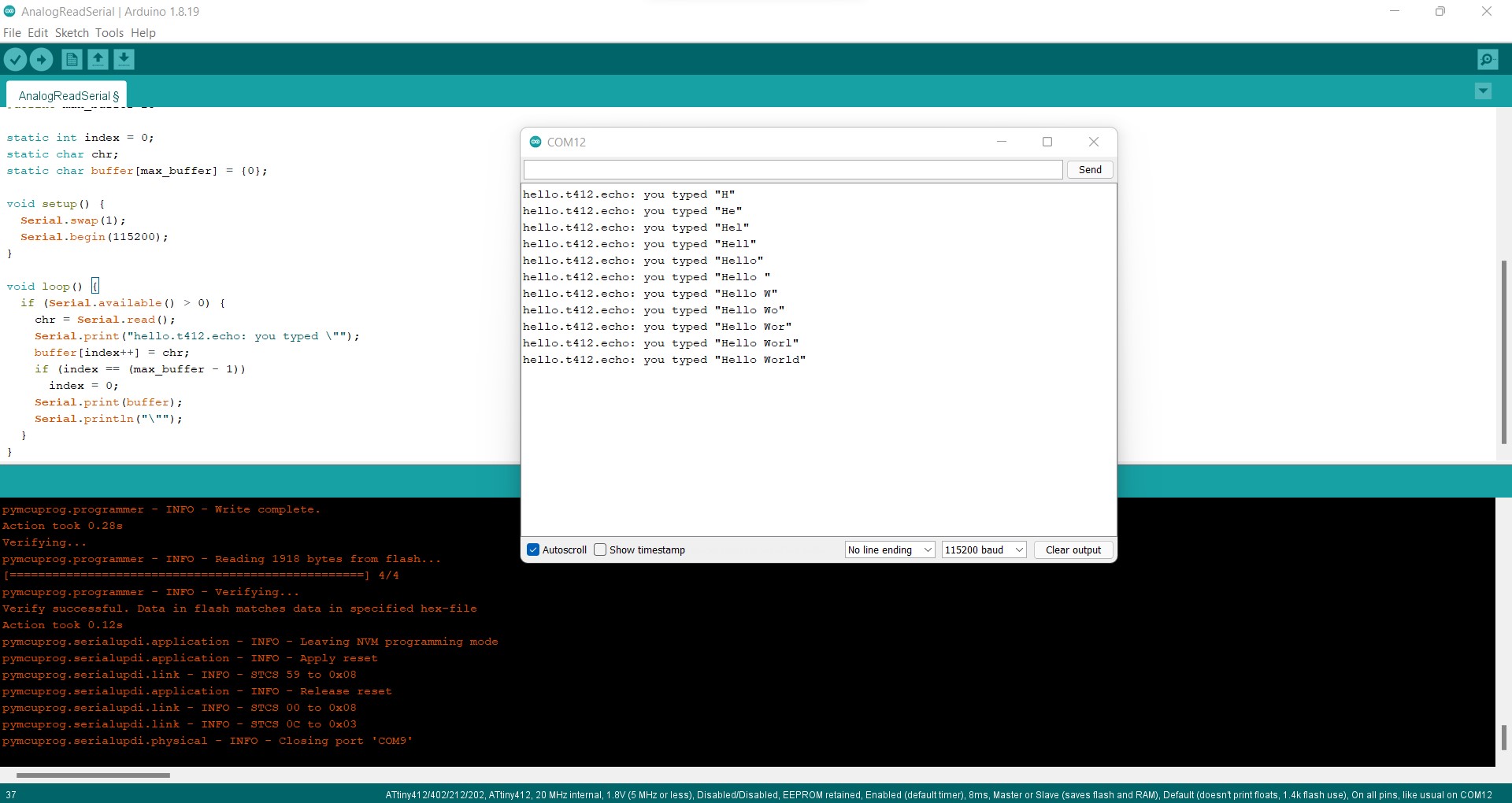
For booting the ATtiny MegaTinyCore from Spence Konde was installed from url
http://drazzy.com/package_drazzy.com_index.json
Click here to learn how to install the setup.and uploaded tiny412 echo hello-world by Neil Gershenfeld and found that the board is working.
Testing Equipments (Group Assigment)
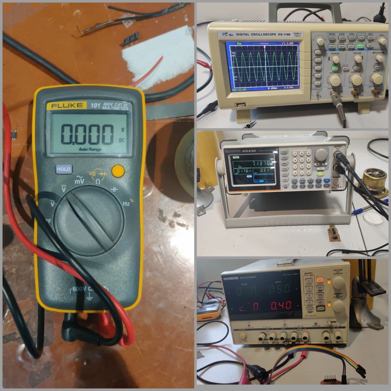
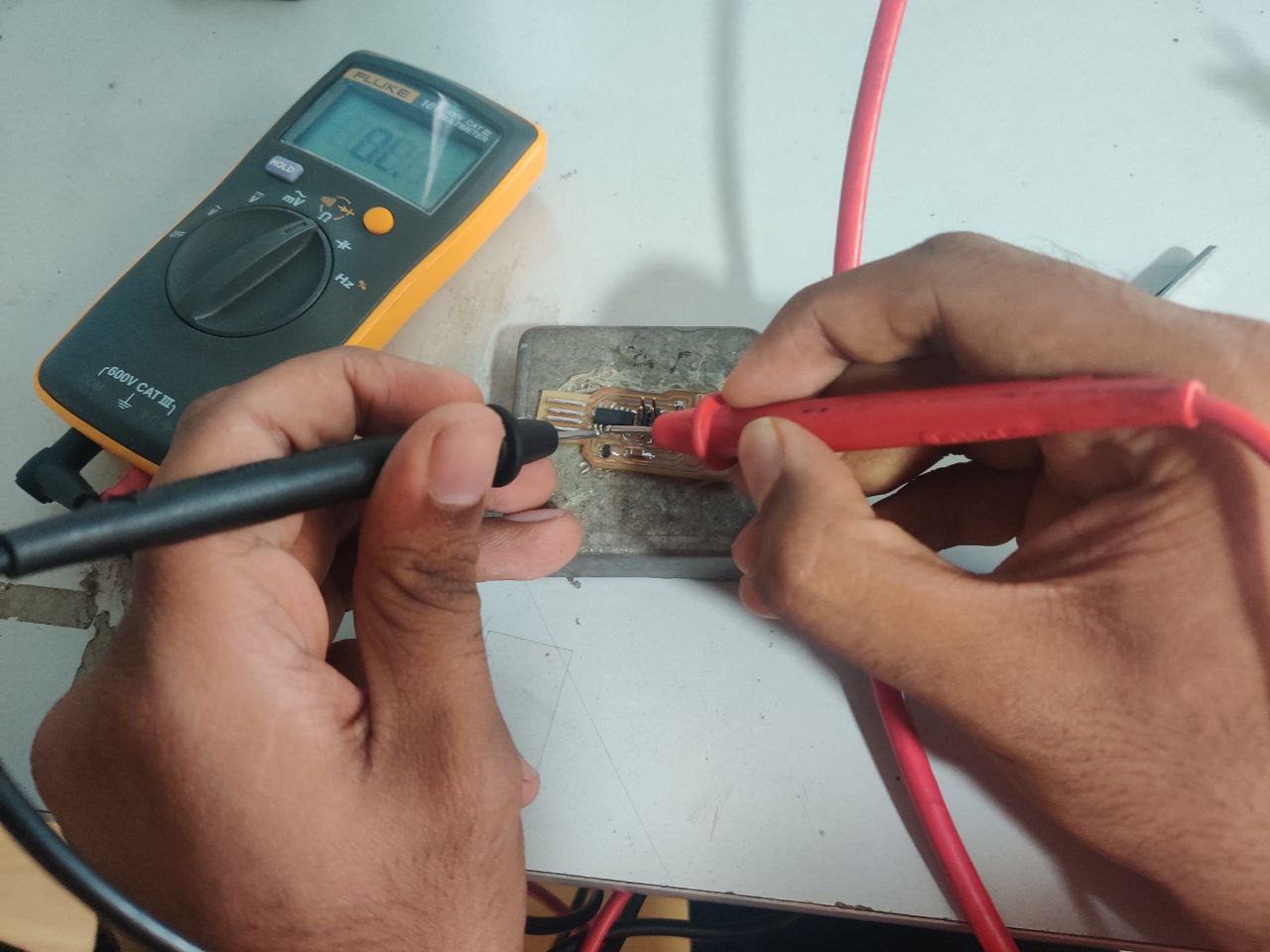
FLUKE 101 Pocket Digital Multimeter
it measures AC/DC voltage, Current, Continuity, Resistance, Frequency, Capacitance it has a basic dc accuracy 0.5%, CAT III 600 V safety rated, diode and continuity test with buzzer, small lightweight design for one-handed use, rugged, durable design, and automatic shutdown
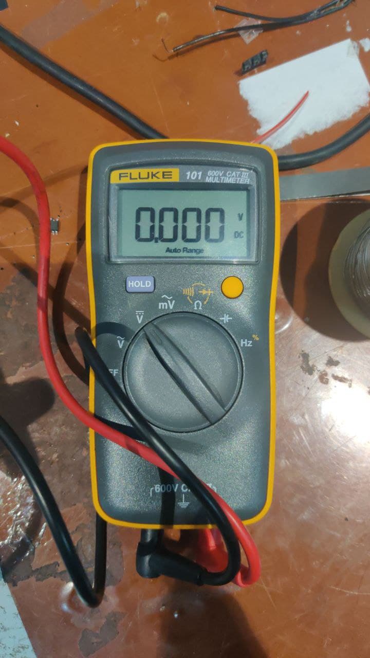
I used it for checking the continuity of the traces by rotating the nob to the Ohm fuction which have mutiple testing modes like finding resistence, to checking wether a diode is working or not, and finally checking continuity we need to press the yellow button on the right side to navigate through these options.
INSTEK GPD-3303D Power Supply
Instek GPD-3303D is a Multiple Output Programmable Linear D.C. Power Supply it have 2/3/4 Independent Isolated Output, LED Display, 1mV/1mA(GPD-2303D/GPD-3303S/GPD-4303S), 100mV/10mA(GPD-3303D) 4 Sets Save/Recall, Tracking Series and Parallel mode, USB Standard Interface, and Labview driver
.jpg)
UNISOURCE DS-1100 100 MHZ, 2 CH, Digital Storage Oscilloscope
The digital storage oscilloscope is an instrument which gives the storage of a digital waveform or the digital copy of the waveform. It allows us to store the signal or the waveform in the digital format, and in the digital memory also it allows us to do the digital signal processing techniques over that signal. The maximum frequency measured on the digital signal oscilloscope depends upon two things they are: sampling rate of the scope and the nature of the converter. The traces in DSO are bright, highly defined, and displayed within seconds. it have 100 MHz bandwidth, 1 M Memory, USB storage, RS232C & J45 interface,4000 point record length for each channel,Multi-waveforms math, FFT Function, Cursor & Track measurement, Waveform Record & Recall, Trigger Mode for Edge, Video, Pulse Width, Slope & Alternate
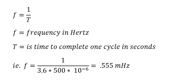
.jpg) we can find the frequency of the board/program by checking the signals using oscilloscope upload a program to the board wich turns a pin high and low without any delay
we can find the frequency of the board/program by checking the signals using oscilloscope upload a program to the board wich turns a pin high and low without any delay
int Pin_num = 2 ;
void setup() {
pinMode(Pin_num, OUTPUT);// initialize digital pin Pin_num as an output.
}
// the loop function runs over and over again forever
void loop() {
digitalWrite(Pin_num, HIGH);   // turn the PIN on by making the voltage HIGH
digitalWrite(Pin_num, LOW);    // turn the PIN off by making the voltage LOW
}
now connect the pin and ground to the oscilloscope we can find the Seconds/div in the middle bottom of the screen with a M on its side using the wave fromed and the division value we can find the frequency of the board.
.jpeg)
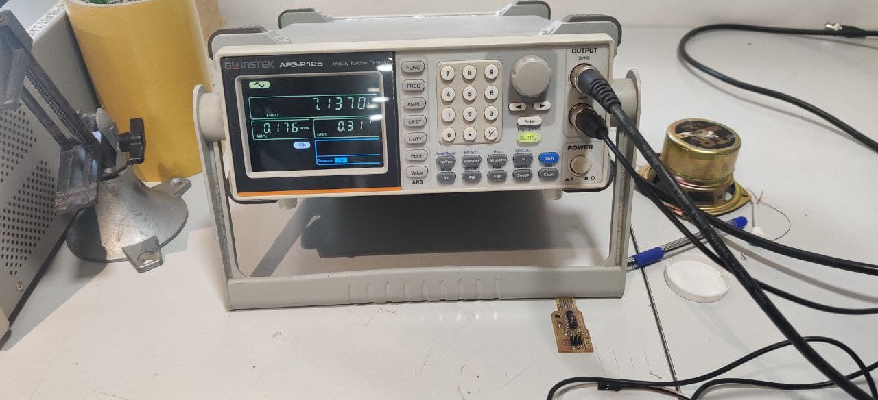
INSTEK AFG-2100/2000 SERIES ARBITRARY FUNCTION GENERATOR
A function generator is a specific form of signal generator that is able to generate waveforms with common shapes. Unlike RF generators and some others that only create sine waves, the function generator is able to create repetitive waveforms with a number of common shapes. The AFG-2100/2000 Series Arbitrary Function Generator is a DDS (Direct Digital Synthesized) based signal generator designed to accommodate the Educational and Basic Industrial requirements for an accurate and affordable signal source covering the output of Sine, Square (Pulse), Ramp (Triangle), Noise and Arbitrary waveforms.it have 0.1Hz to 25MHz with in 0.1Hz Resolution, Sine, Square, Triangular, Noise and, Arbitrary Waveform, 1% ~ 99% adjustable duty cycle for Square Waveform, Waveform Parameter Setting Through Numeric Keypad Entry & Knob Selection, Amplitude, DC Offset and Other Key Setting Information Shown on the 3.5” LCD Screen Simultaneously, AM/FM/FSK Modulation, Sweep, and Frequency Counter Functions (AFG-2100 only), PC Arbitrary Waveform Editing Software