18. Wildcard week
Mechatronika M10V Pick and Place System with Vision
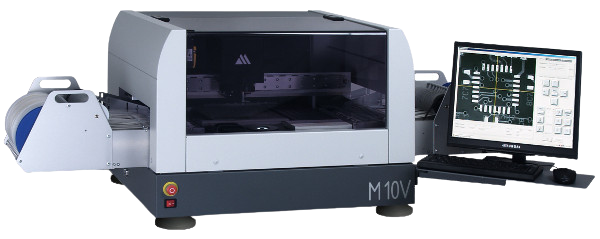 Mechatronika’s M10V Pick and Place System is a versatile automatic machine for placing SMD components from 0201 to 40 x 40 mm with a full vision, touchless component centering.Matured, high quality rigid construction, ease of programming make M10V perfectly suited for small scale production lines and prototyping.
M10V combines mechanical accuracy with high quality pattern recognition system built into easy to use and powerful programming software. M10V excelles in productivity and flexibility, quick change-over and low maintenance requirements.
The very unique feature of M10V is its ability to pickup bulk (loose) components from container-type feeders. M10V built-in intelligent vision system enables to locate required component, pick it up, determine its position on the nozzle head and precisely place it on preprogrammed position. M10V accepts any number of bulk component feeders that can fit within its working space.M10V can be equipped with with the optional glue / solder paste dispensing head
Mechatronika’s M10V Pick and Place System is a versatile automatic machine for placing SMD components from 0201 to 40 x 40 mm with a full vision, touchless component centering.Matured, high quality rigid construction, ease of programming make M10V perfectly suited for small scale production lines and prototyping.
M10V combines mechanical accuracy with high quality pattern recognition system built into easy to use and powerful programming software. M10V excelles in productivity and flexibility, quick change-over and low maintenance requirements.
The very unique feature of M10V is its ability to pickup bulk (loose) components from container-type feeders. M10V built-in intelligent vision system enables to locate required component, pick it up, determine its position on the nozzle head and precisely place it on preprogrammed position. M10V accepts any number of bulk component feeders that can fit within its working space.M10V can be equipped with with the optional glue / solder paste dispensing head
Specification
| PCB | Placement area 300 x 400 mm |
| Feeders | Max 40 feeders of 8mm tapes or 32 feeders of 8mm tapes + 20 sticks of SO8 |
| Components | Range from 0201 to 40 x 40 mm |
| Pitch up to 0.5 mm | |
| Component packing | Tapes 8 mm, 12 mm, 16 mm, 24 mm, 32 mm, 44 mm |
| Sticks SO8–PLCC84 | |
| Trays | |
| Bulk / loose components | |
| Placement rate | 1200 - 1600 cph |
| Placement accuracy | Better than 0.08 mm |
| Nozzle changer | Automatic, 8 nozzles |
| Automatic sensing of nozzle presence | |
| XY resolution | 5µm, (linear encoders as standard) |
| Vision system | Automatic fiducial correction |
| Automatic bad mark sensing | |
| Automatic bulk components feeding | |
| Touchless component centering | |
| Angle resolution | 0,05º |
| Control Panel | LCD 17’’ screen |
| Keyboard | |
| Mouse | |
| Options | Data import from CAD |
| Dispensing head (glue/paste) | |
| Tape strips feeder | |
| Bulk / loose components feeder | |
| Dimensions and weight | 750 x 830 x 550 mm, |
| 70 kg | |
| Power Supply | 230 V, 50 Hz, 400 W |
| Compressed Air Supply | 0,6 MPa, 20 l/min |
Features
- Vision Centering
- Fully automated placing
- Automatic fiducials correction and bad mark sensing
- Automatic change of nozzles
- Automatic feeding of bulk / loose components
- Pick & Place data can be entered manually in TEACH-IN mode or can be converted from various CAD data systems
- Good price to performance ratio
Placing the PCB & Components
Placing PCB is prety easy the machine hase a spring loaded clamp the pcb can be placed by manualy pushing the clamp to a side and place the pcb and the spring will retain the clamp when we relaease it if the dimention of the pcb doesint fitinside the clamp we need to unscrew the clamp and udgest the position accordingly.
(The board we are used here is the one we had sent on week 5 to JLC PCB for board house production.)
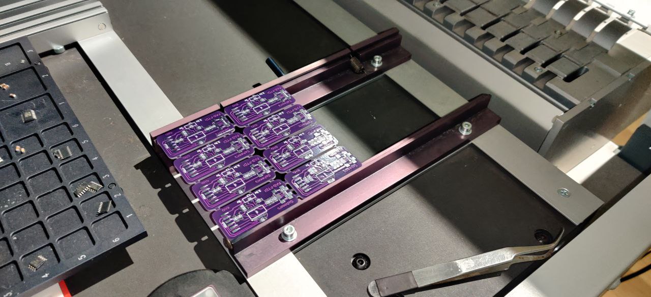
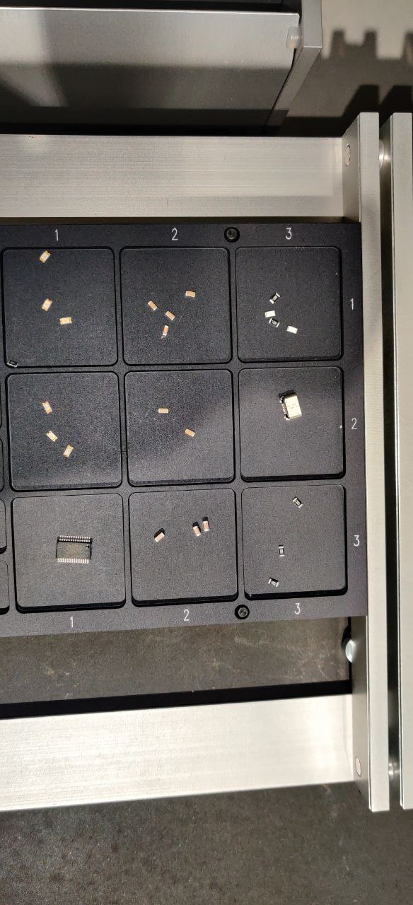
and we need to place the SMD componets in the trays as shown belove make sure that components should be placed upright as the machine canot flip the componet
Setting Up Machine
Opening The Program
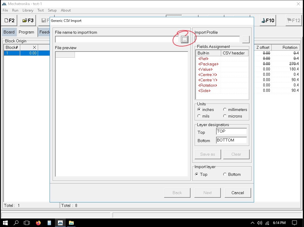
Turn on the machine and PC connected to it now open the application Mechatronika(Fig.1 in slider) > Loding Screen appears > Machine resets > software opens(Fig.3 in slider)


while loading the software the machine will get reseted
Creating and Training New Container
Click on Feeders(Fig.1 in slider) > Right Click Stationary > Add Feeder > New(Fig.2 in slider). In the Poped up dialuge box select Matrix Tray > Click OK(Fig.3 in slider).
Now a new container is created now scroll down to find the newly created container now Right CLick and select Set Pickup Position....(Fig.4 in slider).
A new popup window will apear were we can either manually type in the position of the tray or show the machine were it is, Here we are not going to use manual metord so hereby clcik on Teach In Radio button > select Top Left Coordinate/Bottom Right Coordinate > Click OK(Fig.5 in slider).
Position the camera(cross hairs)to the caressponding positions earlier selected > click OK(Fig.6 in slider).
Now to set the Hight of pickup Right CLick on the created container > Select Set Pickup Height…>(Fig.8 in slider).Use Measure in Set by and Show Position with as Camera and Click Measure > Click OK(Fig.9 in slider) > the prob automatically finds the hight while showing it in the controll panel window > make sure to click OK(Fig.10 in slider).
Now select the SMD component which is to be placed inside the container Right click Container agian (Fig.11 in slider)> select Load Components… > Select Browsw Library in the poped up window(Fig.12 in slider). > Select the component and click OK(Fig.13 in slider).


Adding a New Component
for adding a new SMD component first we need to go to Browse Library > Right click on the file location > New > Package(Fig.1 in slider). Enter the name of new package in the Package window > click OK(Fig.2 in slider).
in the window that pops up after creating a new package have 4 sections(Fig.3 in slider).


-
Specification
-
Enter the size of the package as per in the data sheet in
- Length[X](mm)
- Width [Y](mm)
- Height (mm)
-
Enter the size of the package as per in the data sheet in
-
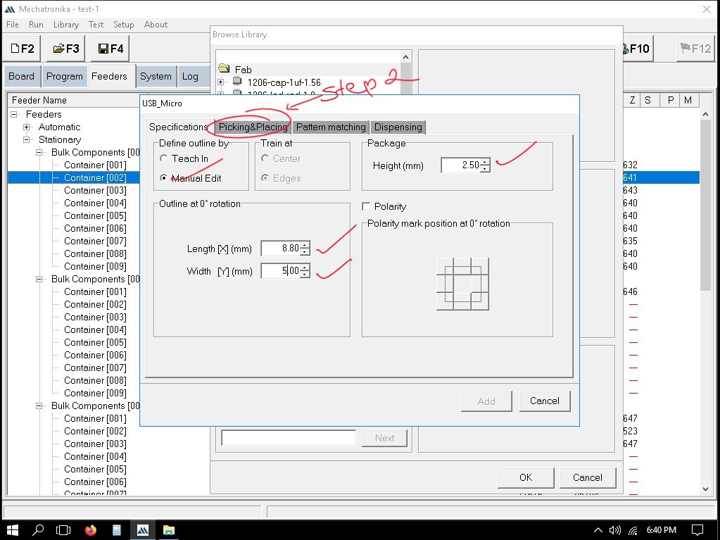
Picking&Placing
-
Change the machine parametersand set the nozzle according to the componoent(Fig below).
-
Change the machine parametersand set the nozzle according to the componoent(Fig below).
-
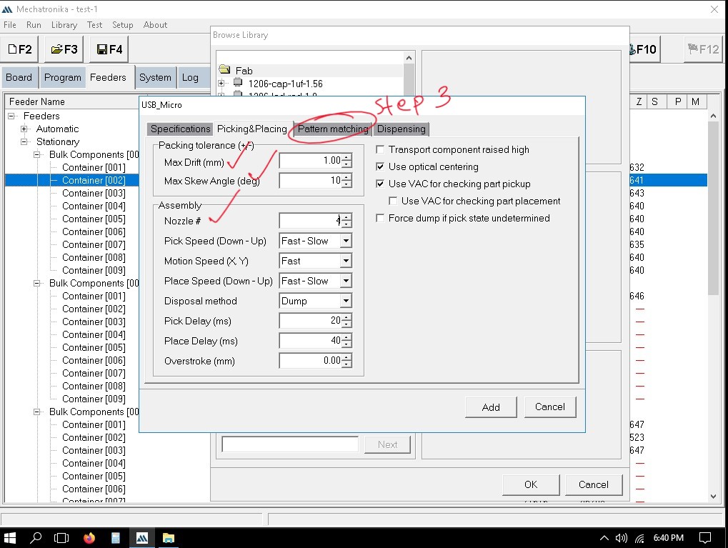
Pattern Matching
-
Top CAM
- Click Learn(Fig.1 in slider) > wich will open contol panel were you have to adjust the crosshairs over the component and click OK(Fig.3 in slider) >
- Click Learn(Fig.1 in slider) > wich will open contol panel were you have to adjust the crosshairs over the component and click OK(Fig.3 in slider) >
-
Bottom CAM
- Bottom also have the same pocedure but make sure the Pattern Type is set to Dual as the componts bottom is not in symmetric(Fig.1 in slider). and we need to train 2 points at 2 diogonal edges of the component in training section(Fig.3 in slider)
- Bottom also have the same pocedure but make sure the Pattern Type is set to Dual as the componts bottom is not in symmetric(Fig.1 in slider). and we need to train 2 points at 2 diogonal edges of the component in training section(Fig.3 in slider)
-
Top CAM
-
Dispencing
- In Dispensing Press Add dropdown > select Single Dot(Fig.1 in slider). Select Teach In then click on Dot To open contorl Panel(Fig.2 in slider). Position the cross hairs to the places were to dispence the paste(Fig.3 in slider) > Click OK.similerly add all the other points and click OK(Fig.4 in slider).


Exporting .csv file
Open the PCB file in fusion > Go to MANUFACTURING > Click on CAM Processor > In Output file select Pick and Place under Assembly section inside the poped up window. > change the Output Type to CSV > Click Export Fileand select the file destination > to view the file click Open folder on the next window that appears after exporting.
for downloading file Click here
Importing .csv to Mechatronika
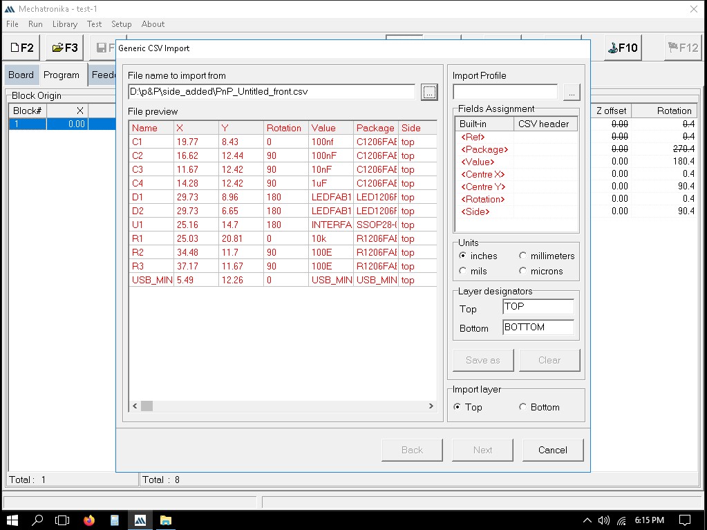
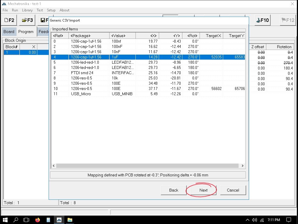
Open Mechatronika > Click Program > right click on any blank space inside Parts Placement Section > Import> Generic CSV file
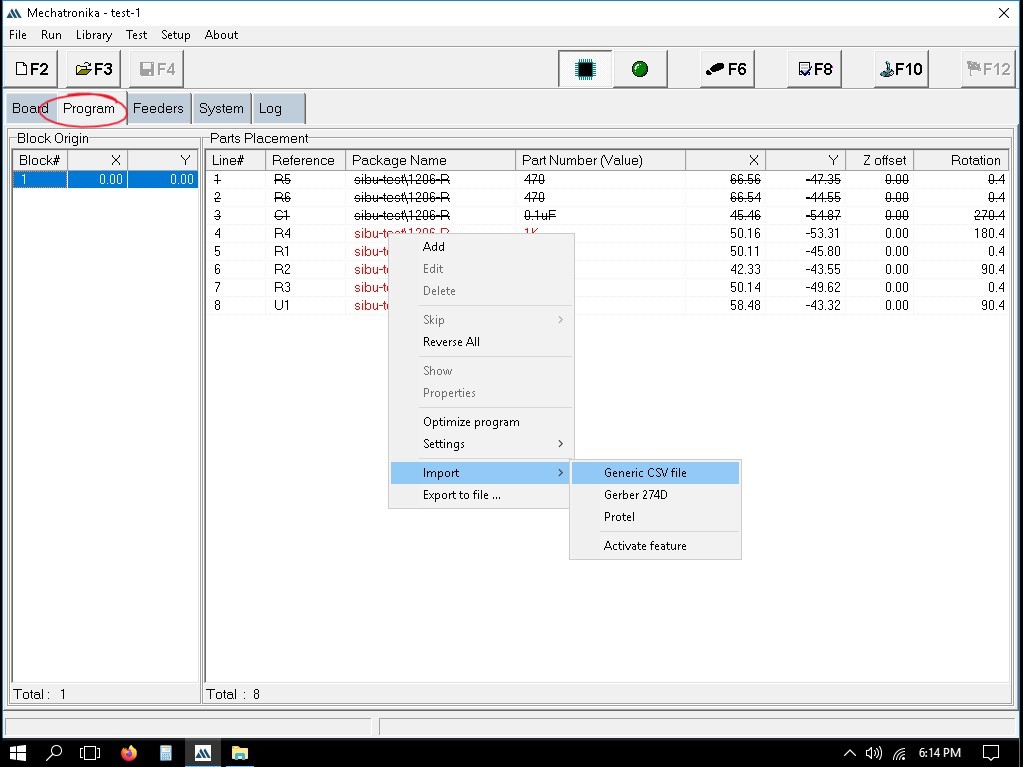 a window named Generic CSV Import will appear
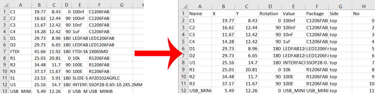
> import file by pressing the button below File name to import from > the file will be previewed under File Preview section and now we need to assign buildin parameters to CSV headers
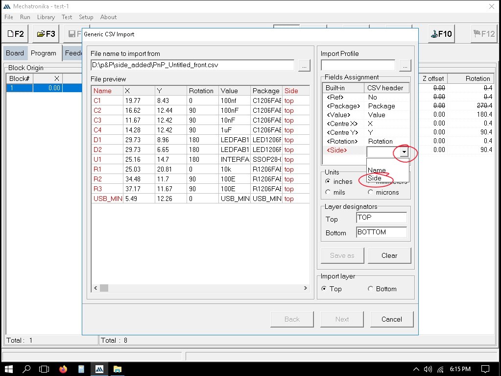
> click on the drop down under each CSVheader and match the corresponding header to built-in
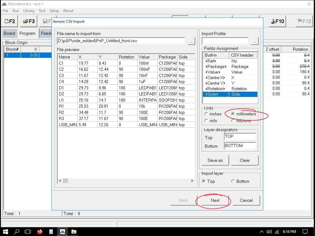
> make sure Unit is in millimeters and Click Next
In the next window we need to assign packages we earlier created to the imported file. for this right click on the package name under Package Assigment > click Assign Package
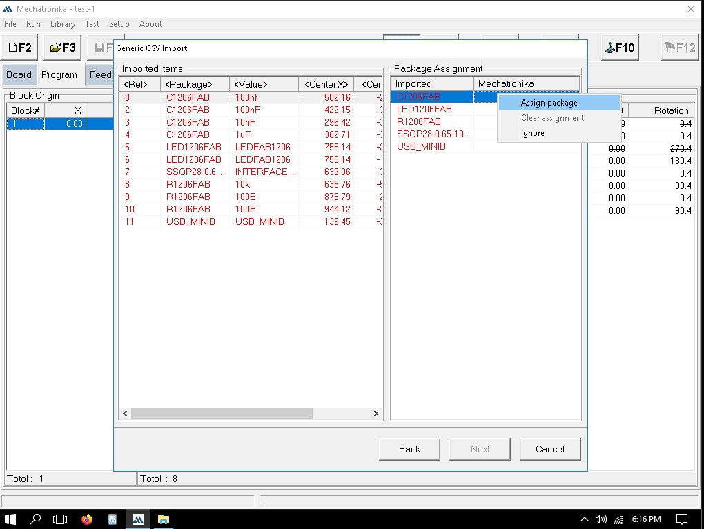
> Browse Library opens select the corresponding package and click OK
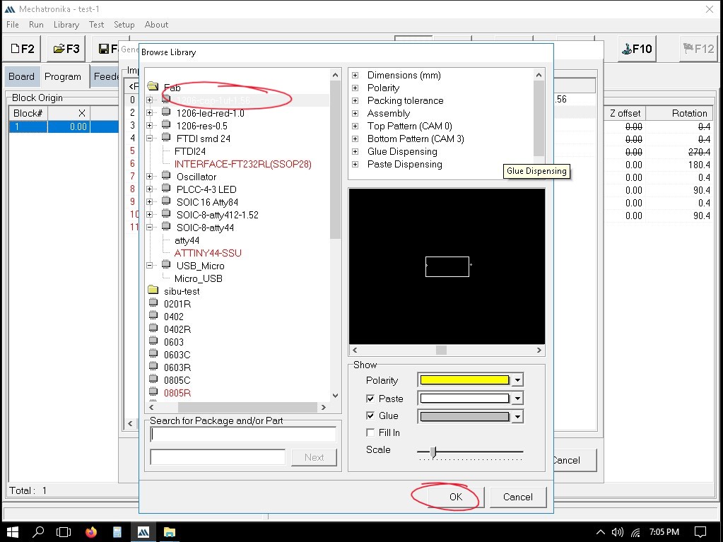
. > do the same for all and click Next
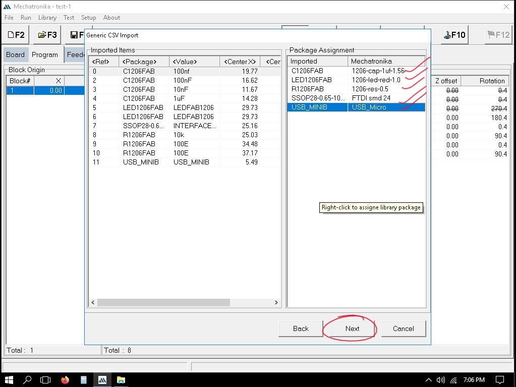
Now on the next window we need to map any two of the component tofind the relative poition of the bord in the bed. Right click on the component in red > click on Map to target position
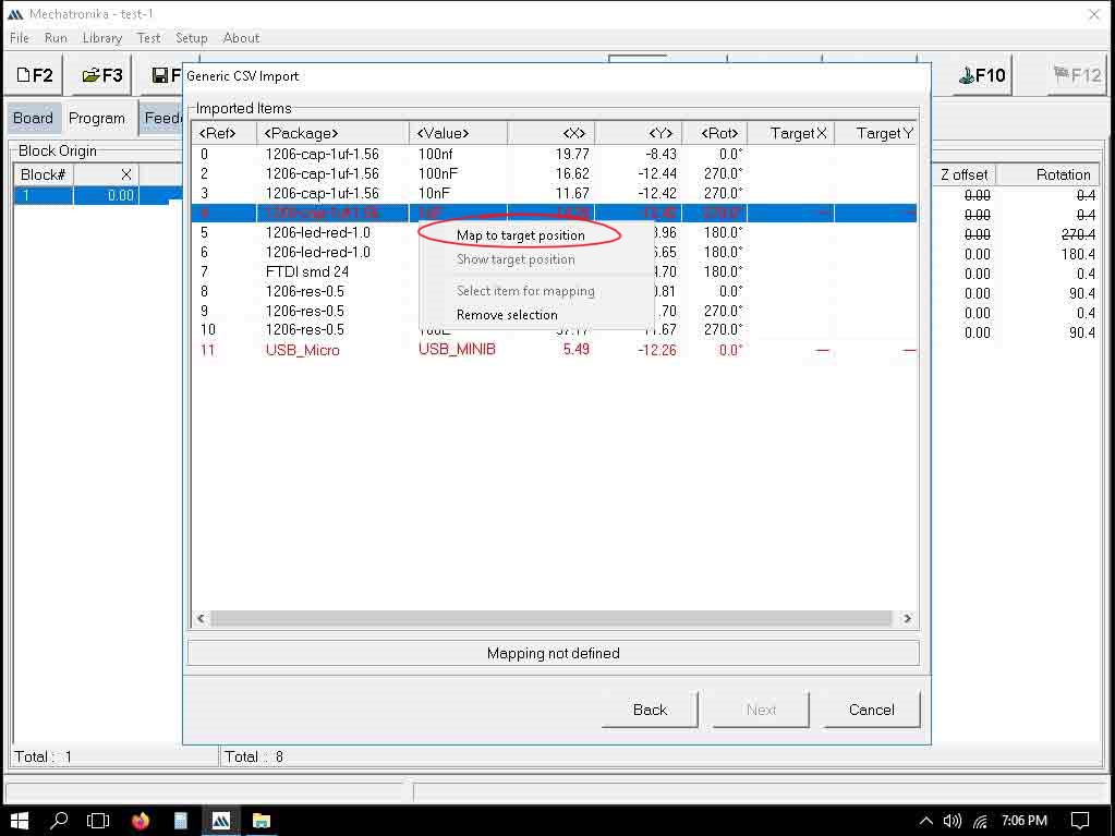
Control panel will open up and position the component accordingly > and Click OK.
Running the Program
Dispencing solder paste
now everthing is done we can dispence the paste by selecting the green dot on the top and pressing F12 on the keybord.
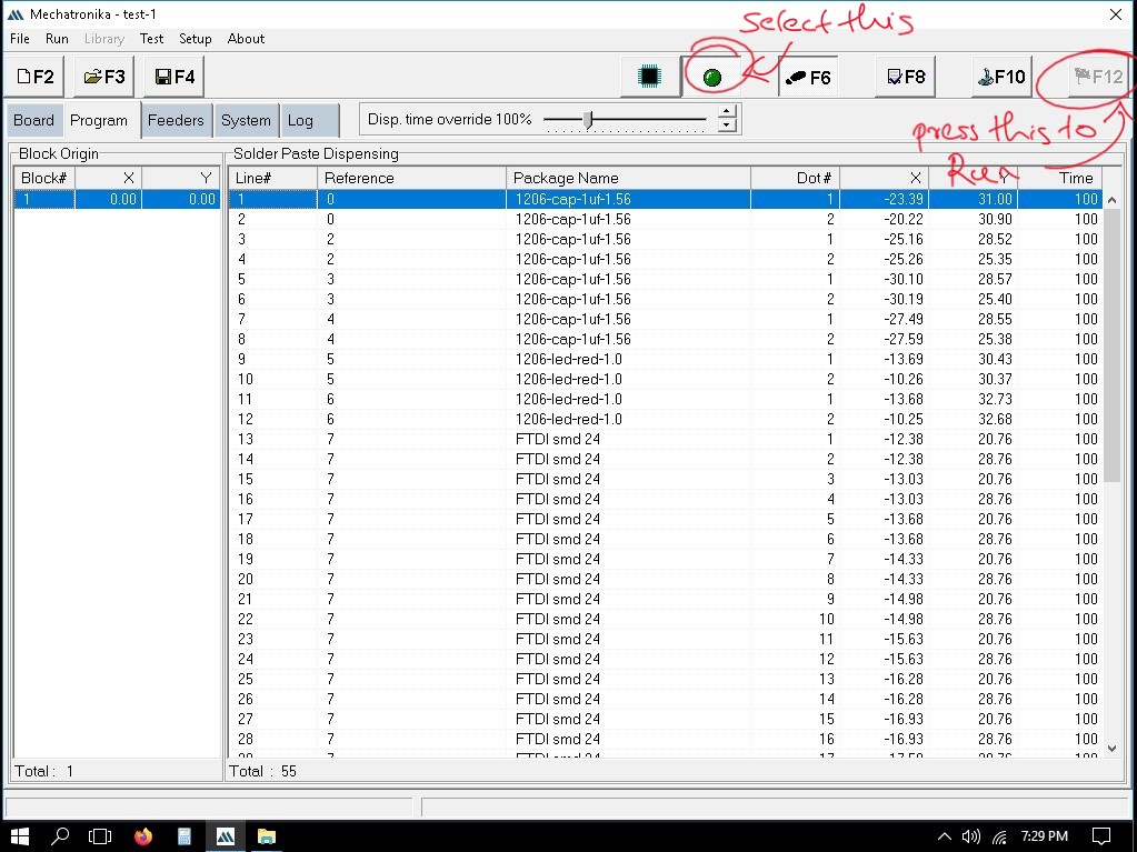
the machine will start dispencing on the pre difined points of each components.
Placing the components
now everthing is done we can start placin the components by simply by selecting the chip with the blue legs on the top and pressing F12 on the keybord.
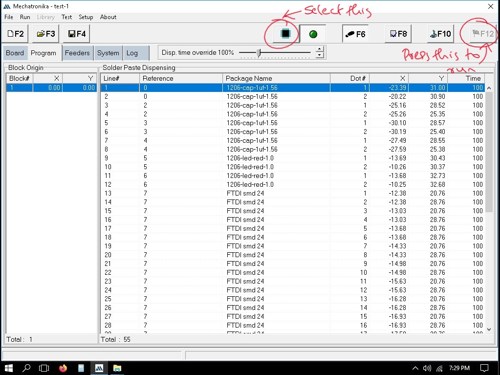
the machine will start placing the components on the pre difined points of each components as per the csv file.
Soldering
the pcb is carefully removed from the clap and used hot air reflow methord to solder the placed components other non SMD components were solderd by using normal lead and soldering iron methord.
Result
.jpeg)
OMAX 5555 PRECISION JETMACHINING CENTER
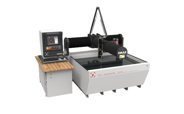
OMAX 5555 PRECISION JETMACHINING CENTER is a is an industrial water jet cutting machine capable of cutting a wide variety of materials using an extremely high-pressure jet of water, or a mixture of water and an abrasive substance. The term abrasive jet refers specifically to the use of a mixture of water and abrasive to cut hard materials such as metal, stone or glass. The fast, efficient, and precise 5555 JetMachining® Center provides top performance in waterjet machining of complex parts from many materials. From simple metals to complex composites, the 4’ 7” square cutting area of the proven 5555 is ideal for rapid prototyping and just-in-time manufacturing of small to medium-sized parts. With simple fixturing and easy access to the cutting table, setup times are significantly reduced, increasing productivity and profitability.
Specification
| MATERIAL SUPPORTS SLATS | 4” x 1/8” Galvanized Steel |
| MAXIMUM SUPPORTED MATERIAL LOAD | 400 lbs/sq ft (1,950 kg/sq meter) |
| ELECTRICAL REQUIREMENTS | 3-Phase, 380-480 VAC ±10%, 50-60 Hz |
| NOISE LEVEL | Below 80 dBA at one meter for submerged cutting |
| SPEED | 180 in/min (4,572 mm/min) |
| LINEAR POSITIONAL ACCURACY* | ±0.001” (±0.025 mm) |
| REPEATABILITY* | ±0.001” (±0.025 mm) |
| BALLBAR CIRCULARITY* | ±0.003” (±0.076 mm) |
| FOOTPRINT (WITH PUMP) | 10’ 11” x 7’ 11” (3,327 mm x 2,413 mm) |
| HEIGHT (WITH SCISSOR PLUMBING) | 9’ 10” (2,997 mm) |
| OPERATING WEIGHT | 13,000 lb (5,897 kg) |
| WEIGHT (TANK EMPTY) | 6,291 lb (2,854 kg) |
| X-Y CUTTING TRAVEL* | 4’ 7” x 4’ 7” (1,397 mm x 1,397 mm) |
| Z-AXIS TRAVEL (WITH MOTORIZED Z AXIS)* | 8” (203 mm) |
| TABLE SIZE | 6’ 8” x 5’ 5”(2,032 mm x 1,651 mm) |
Features
- Fastest cutting speeds and best precision compared to any abrasivejet in the industry and is backed by our exclusive Intelli- MAX® Software with real world cutting data
- Programmable Motorized Z-Axis with a precision OMAX MAXJET®5i Nozzle Assembly can boost cutting productivity and process efficiency
- Tilt-A-Jet® taper compensating abrasivejet cutting head (available as an option)
- Precision X-Y Axis rigidly mounted to the cutting table
- Pre-loaded linear bearings and precision ball screws
- Low maintenance, high reliability scissor-style hard plumbing
- Drive system sealed against water, dirt, and grit
- Easy operator access to the work area
- High efficiency Generation 4 EnduroMAX® pump systems available in 30, 40, or 50 hp with operating efficiencies up to 85%
- Robust and accurate design for tight tolerance cutting and reliable operation
- Optional Variable Speed Solids Removal System (VS-SRS) designed for tough industrial use increases uptime through automated solids removal
- Machines a wide range of materials and thicknesses, from metals and composites to glass and plastics
- Does not create heat-affected zones or mechanical stresses
- No tool changes and minimal fixturing reduces setup by 50% or more
- No additional water required for pump cooling
- Small, efficient footprint for minimal floorspace utilization
- Leaves behind a satin-smooth edge, reducing secondary operations
- No noxious gases, liquid and oils used in, or caused by, the machining process EnduroMAX pump technology delivers the highest nozzle horsepower in the industry for faster and more efficient cutting
- Completes most work below 80 dBA
- Environmentally “green” system with quiet and clean operation with low electrical consumption
- Rapid Water Level Control for quiet and clean submerged cutting
- Highly robust and reliable pump design capable of over 1000 hours between maintenance.
Setting up Machine
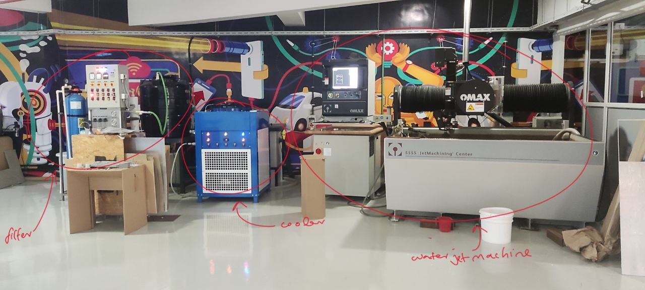
machine have mainly 3 parts a water treatment unit wich filters the water from imputities and cancels out the conductivity of the water to zero.Water cooling unit which basically act as a coolent to the machining and recycles the used water to conserve the use of water. Finally the Water Jet Machine machine uses high pressure water and abrasives if needed to cut the work.
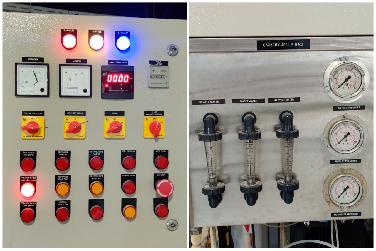
Water Treatment System
turn on the machine filtering unit keep the switch position in auto. turn on the voltmeter and doser. make sure there is no warning indicatoers are lighted, check the pressure gauges and water levels. Wait for the cunductivity to reduce to zero.
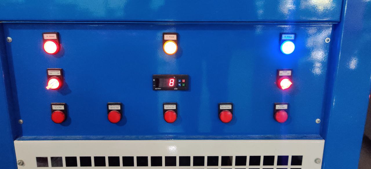
Water Cooling Unit
Check the power supply. Set the temprature in the disply dial. Wait for the temprature to reduce below 16°C. turn on the pump and compressor.