9. Embedded programming
Objectives
Individual
- Read the data sheet for your microcontroller.
- use the programmer to program the board.
- extra credit: trying programming languages and development environments.
Group (To redirect to group assigment page Click here)
- Compare the performance and development workflows for other architectures.
Reading the data sheet
ATtiny412
The ATtiny412 microcontrollers use AVR® RISC architecture and can run at up to 20MHz. They have up to 2/4KB Flash, 128/256bytes of SRAM, and 64/128bytes of EEPROM in an 8-pin package. It has an Event System and SleepWalking, as well as precise analogue features and advanced peripherals.
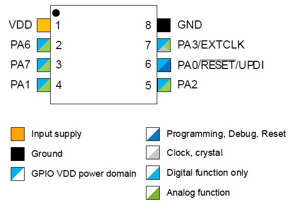
Pin Description
VCC -Supply voltage
GND -Ground
PA0-PA7 -Port A
RESET -Port A
EXTCLK -External Clock
The External Clock is taken directly from the pin.This clock source has a start-up time of 2 cycles when first requested.
UPDI -Universal Program Debug Interface
is an proprietary interface for external programming and on-chip debugging of a device. Programming and debugging is done through the UPDI Physical interface (UPDI PHY), which is a 1-wire UART based half-duplex interface using the RESET pin for data reception and transmission.
Block Diagram and Architecture
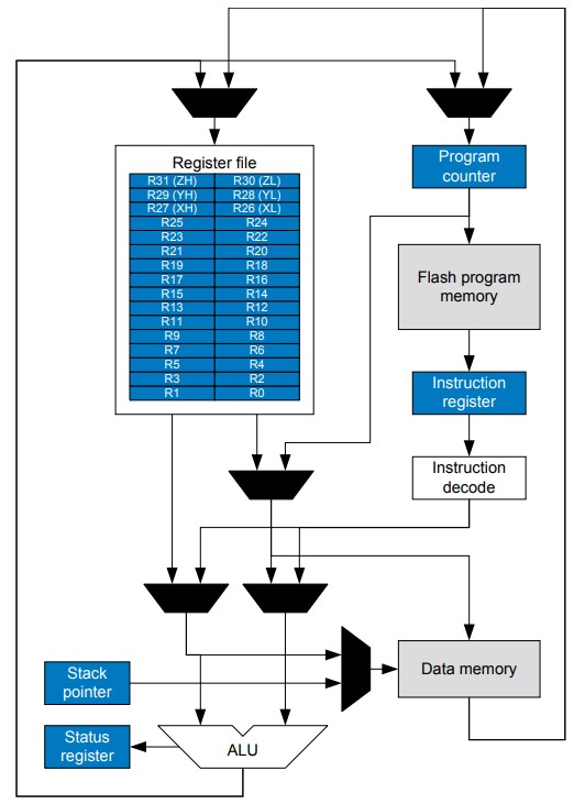
The Attiny412 is powered by an 8-bit AVR CPU. The CPU is capable of accessing memories, performing calculations, controlling peripherals, and executing instructions stored in programme memory. Interrupt handling, on the other hand, is addressed in a separate section.
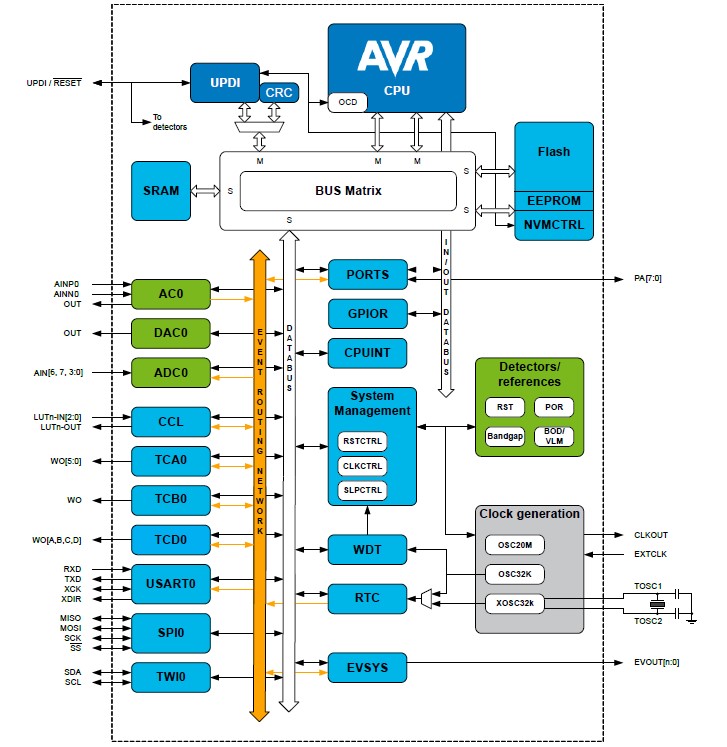
Which employs a Harvard architecture with distinct buses for instruction and data to maximise performance and parallelism. Single-level pipelining is used to execute instructions in programme memory. The next instruction is pre-fetched from programme memory while the previous one is being executed. This permits commands to be executed at the rate of one per clock cycle.
Embedded programing
Arduino IDE
I found that Arduino is by far the easiest way to get started with embedded programming, so I stated using aurdino. To configure Aurdino for the ATtiny 412 and ATtiny 1614, replace the board to the appropriate one in tools. Click here to learn how to install the ATtiny Chips setup.
Click here to get ATtiny412 Arduino mapping
Click here to get ATtiny1614 Arduino mapping
- Blink LED : first I loaded the Examble program blink to the first bord i designed in the Electronics design Week for this go to Files > Examples > 01.Basics > Blink
/* Blink Turns an LED on for one second, then off for one second, repeatedly. Most Arduinos have an on-board LED you can control. On the UNO, MEGA and ZERO it is attached to digital pin 13, on MKR1000 on pin 6. LED_BUILTIN is set to the correct LED pin independent of which board is used. If you want to know what pin the on-board LED is connected to on your Arduino model, check the Technical Specs of your board at: https://www.arduino.cc/en/Main/Products modified 8 May 2014 by Scott Fitzgerald modified 2 Sep 2016 by Arturo Guadalupi modified 8 Sep 2016 by Colby Newman This example code is in the public domain. https://www.arduino.cc/en/Tutorial/BuiltInExamples/Blink */ // the setup function runs once when you press reset or power the board void setup() { // initialize digital pin LED_BUILTIN as an output. pinMode(LED_BUILTIN, OUTPUT); } // the loop function runs over and over again forever void loop() { digitalWrite(LED_BUILTIN, HIGH); // turn the LED on (HIGH is the voltage level) delay(1000); // wait for a second digitalWrite(LED_BUILTIN, LOW); // turn the LED off by making the voltage LOW delay(1000); // wait for a second } - I modified the code to have the two LEDs blink intermittently.
/* int LED_1 = 0; int LED_2 = 1; // the setup function runs once when you press reset or power the board void setup() { // initialize digital pin LED_1 as an output. pinMode(LED_1, OUTPUT); pinMode(LED_2, OUTPUT); } // the loop function runs over and over again forever void loop() { digitalWrite(LED_1, HIGH); // turn the LED on (HIGH is the voltage level) delay(1000); // wait for a second digitalWrite(LED_1, LOW); // turn the LED off by making the voltage LOW delay(1000); // wait for a second } - Then I thought of using the switch as a input to control the LED
const int BUTTON = 4; const int LED = 0; int BUTTONstate = 0; void setup() { pinMode(BUTTON, INPUT); pinMode(LED, OUTPUT); } void loop() { BUTTONstate = digitalRead(BUTTON); if (BUTTONstate == HIGH) { digitalWrite(LED, HIGH); } else{ digitalWrite(LED, LOW); } } - Then I needed the button to function as an ON/OFF switch. so I utilized debouncing technic from the Arduino.cc click here to be redirected to the website.
/*
  Debounce

  Each time the input pin goes from LOW to HIGH (e.g. because of a push-button
  press), the output pin is toggled from LOW to HIGH or HIGH to LOW. There's a
  minimum delay between toggles to debounce the circuit (i.e. to ignore noise).

  The circuit:
  - LED attached from pin 13 to ground through 220 ohm resistor
  - pushbutton attached from pin 2 to +5V
  - 10 kilohm resistor attached from pin 2 to ground

  - Note: On most Arduino boards, there is already an LED on the board connected
    to pin 13, so you don't need any extra components for this example.

  created 21 Nov 2006
  by David A. Mellis
  modified 30 Aug 2011
  by Limor Fried
  modified 28 Dec 2012
  by Mike Walters
  modified 30 Aug 2016
  by Arturo Guadalupi

  This example code is in the public domain.

  https://www.arduino.cc/en/Tutorial/BuiltInExamples/Debounce
*/

// constants won't change. They're used here to set pin numbers:
const int buttonPin = 4;    // the number of the pushbutton pin
const int ledPin = 1;      // the number of the LED pin

// Variables will change:
int ledState = HIGH;         // the current state of the output pin
int buttonState;             // the current reading from the input pin
int lastButtonState = LOW;   // the previous reading from the input pin

// the following variables are unsigned longs because the time, measured in
// milliseconds, will quickly become a bigger number than can be stored in an int.
unsigned long lastDebounceTime = 0;  // the last time the output pin was toggled
unsigned long debounceDelay = 50;    // the debounce time; increase if the output flickers

void setup() {
  pinMode(buttonPin, INPUT_PULLUP);
  pinMode(ledPin, OUTPUT);

  // set initial LED state
  digitalWrite(ledPin, ledState);
}

void loop() {
  // read the state of the switch into a local variable:
  int reading = digitalRead(buttonPin);

  // check to see if you just pressed the button
  // (i.e. the input went from LOW to HIGH), and you've waited long enough
  // since the last press to ignore any noise:

  // If the switch changed, due to noise or pressing:
  if (reading != lastButtonState) {
    // reset the debouncing timer
    lastDebounceTime = millis();
  }

  if ((millis() - lastDebounceTime) > debounceDelay) {
    // whatever the reading is at, it's been there for longer than the debounce
    // delay, so take it as the actual current state:

    // if the button state has changed:
    if (reading != buttonState) {
      buttonState = reading;

      // only toggle the LED if the new button state is HIGH
      if (buttonState == HIGH) {
        ledState = !ledState;
      }
    }
  }

  // set the LED:
  digitalWrite(ledPin, ledState);

  // save the reading. Next time through the loop, it'll be the lastButtonState:
  lastButtonState = reading;
}
Microchip Studio
Microchip Studio is an Integrated Development Environment (IDE) for AVR® and SAM microcontroller application development and debugging. It can be used to write, build, and debug programs written in C/C++ or assembly code. Installing Microchip Studio is a piece of cake download it from this microchip.com and install the setup simple as that.
-
Embedded C
for setting the IDE for Embedded C go to File > New > Project > Select any executable C projects > Click OK
Now lets select the Microcontroler say ATtiny412 Click OK
-
Compiling and Debugging
Paste the below given code to the IDENow, simply to demonstrate how to do some basic debugging, I avoided putting int in front of main so that we can see how errors will appear in Microchip Studio.#include// AVR input/output library #define F_CPU 3555555 // Since we connected a 20MHz crystal into the circuit #include // Delay library #define LED 0b01000000 int main() { PORTA_DIRSET = (1<<7); //set pins 6 in the A port as output pins. while(1) // infinte loop { PORTA_OUT |=(1<<7); //Turns pin6 ON. _delay_ms(1000); //wait for one second. PORTA_OUT &=(!(1<<7)); //Turns pin6 OFF. _delay_ms(1000); //wait for one second. } }
go to Build > Click Build Solution
The Error List can be found at the bottom of the window. Look up the Line number and rectify the error; then, repeat Build > Click Build Solution
-
SETTING UP EXTERNAL TOOL TO FLASH THE MC USING UPDI AND FLASHING
To flash the microcontrollers using UPDI, we must first set up an external tool. for that go to Tools > External Tools..
Enter a Title: say UPDI paste the pyupdi.exe file location in Command: sectionClick here to find how to install pyupdi.C:\Users\xxxx\AppData\Local\Programs\Python\Python310\Scripts\pyupdi.exe
Now set the Arguments: asand set the Initial directory: as-d tiny412 -c COM10 -b 9600 -f $(TargetDir)$(TargetName).hexfor programming the MC go to Tools > Click UPDI/(whatever title you had given in External tool setup)$(TargetDir)x
- Output
-
Compiling and Debugging
- Assembler
for this go to File > New > Project > Assembler > AVR Assembler Project > Click OK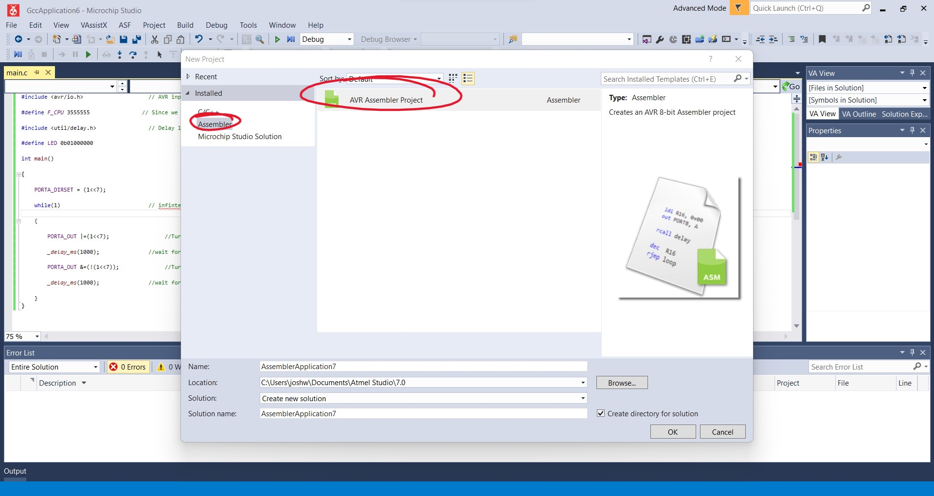
Saheen Palayi, a continuing student in our lab, helped me on creating my first assembler program to blink the LED. Despite the fact that the programme did not perform as intended since the delay timing was simply too little to perceive with our naked eyes, it was a good start for us.; ; Blynk.asm ; ; Created: 19-03-2022 13:33:16 ; Author : Saheen_Palayi ; .include "tn412def.inc" ; Replace with your application code sbi VPORTA_DIR,4; PB0 as output, driver stage on, 2 clock cycles Loop: cbi VPORTA_OUT,4 ; LED on, 2 clock cycles nop ; do nothing, 1 clock cycle nop ; do nothing, 1 clock cycle sbi VPORTA_OUT,4 ; LED off, 2 clock cycles rjmp Loop ; Jump relative back to label Loop, 2 clock cycles.include "tn412def.inc" sbi VPORTA_DIR,6; PB0 as output, driver stage on, 2 clock cycles loop: sbi VPORTA_OUT,6 ; clr r19 rjmp Delay_1sec loop2: cbi VPORTA_OUT,6 ; inc r19 rjmp Delay_1sec Delay_1sec: LDI r16, 15 Delay1: LDI r17, 255 Delay2: LDI r18, 255 Delay3: DEC r18 BRNE Delay3 DEC r17 BRNE Delay2 DEC r16 BRNE Delay1 cpi r19, 0 breq loop2 rcall loop
OTHER ARCHITECHTURES
MSP-EXP430G2ET (RISC architecture)
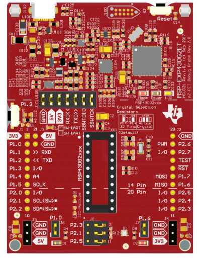
- 1.8-V to 3.6-V operation
- 16-bit RISC architecture up to 16-MHz system clock
- 16KB of flash memory and 512 bytes of SRAM
- 8-channel 10-bit ADC
- 8-channel comparator
- Two 16-bit timers with three capture/compare registers (Timer_A)
- 24 GPIOs
- One universal serial communication interface (USCI_A) supports UART, IrDA, and SPI
- One USCI (USCI_B) supports SPI and I2C
we can use Energia IDE for programming and for that we need to download some drivers from official TI site
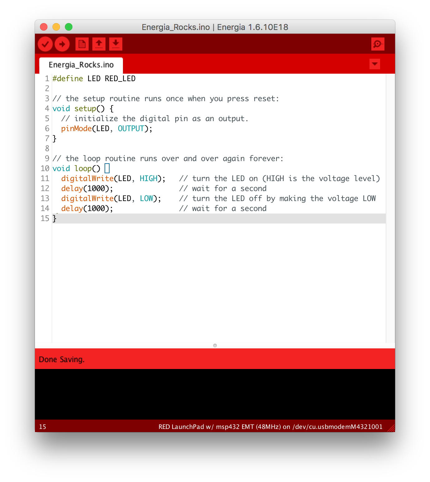 I ran basic blink example on the board.
/*
  Blink

  Turns an LED on for one second, then off for one second, repeatedly.

  Most Arduinos have an on-board LED you can control. On the UNO, MEGA and ZERO
  it is attached to digital pin 13, on MKR1000 on pin 6. LED_BUILTIN is set to
  the correct LED pin independent of which board is used.
  If you want to know what pin the on-board LED is connected to on your Arduino
  model, check the Technical Specs of your board at:
  https://www.arduino.cc/en/Main/Products

  modified 8 May 2014
  by Scott Fitzgerald
  modified 2 Sep 2016
  by Arturo Guadalupi
  modified 8 Sep 2016
  by Colby Newman

  This example code is in the public domain.

  https://www.arduino.cc/en/Tutorial/BuiltInExamples/Blink
*/

// the setup function runs once when you press reset or power the board
void setup() {
  // initialize digital pin LED_BUILTIN as an output.
  pinMode(LED_BUILTIN, OUTPUT);
}

// the loop function runs over and over again forever
void loop() {
  digitalWrite(LED_BUILTIN, HIGH);   // turn the LED on (HIGH is the voltage level)
  delay(1000);                       // wait for a second
  digitalWrite(LED_BUILTIN, LOW);    // turn the LED off by making the voltage LOW
  delay(1000);                       // wait for a second
}
STM32 Nucleo (ARM Cortex)
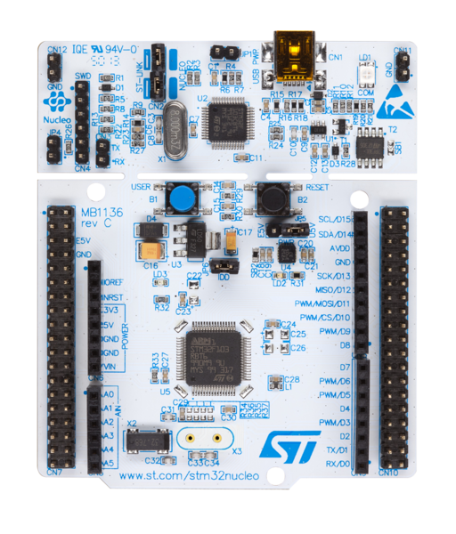
- ARM Cortex M4 CPU with FPU
- 2.4uA at standby without RTC
- 84 MHz CPU Frequency
- 4 to 26 MHz Crystal Oscillator Range
- 1.7V to 3.6V MCU Operating Voltage (VDD)
- 7V to 15V Board Operating Voltage (VIN)
- 512KB Flash Memory
- 96 KB SRAM
- 50 GPIO Pins
- 12-bit 16Channel ADC
- In-built 32kHz with calibration RTC
- 16-bit (6) & 32-bit (2) Timers
- 2 Watchdog Timers
- 4 USART/UART Communication
- 3 I2C Communication
- 3 SPI Communication
- Serial Wire and JTAG On Board Debugger
we can use Mbed OS for programming which is a online IDE and export the program and just past it into the flash directory of the Nucleo development board.
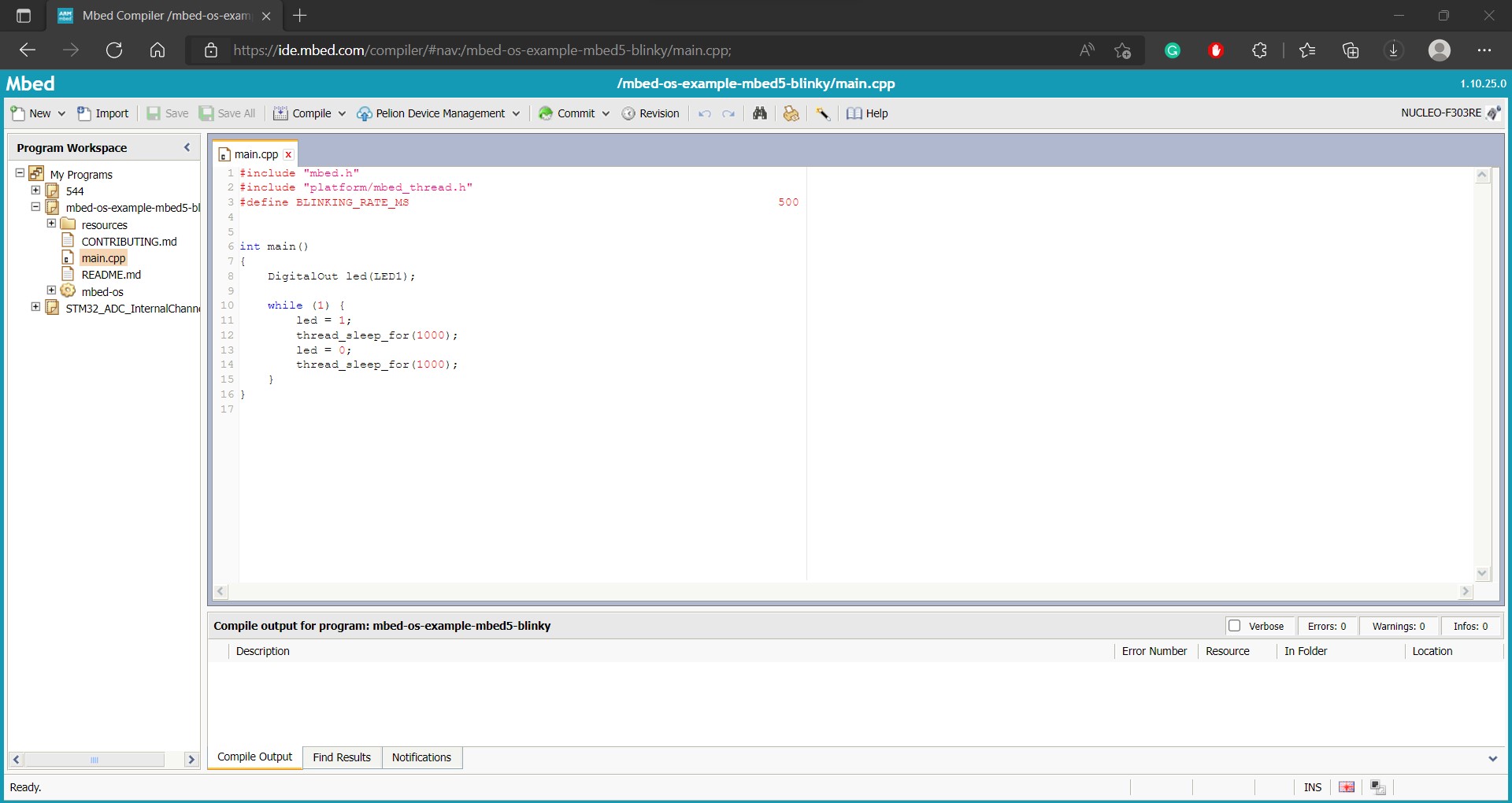
So here also we tried a simple blink program.
#include "mbed.h"
#include "platform/mbed_thread.h"
#define BLINKING_RATE_MS                                                    500


int main()
{
    DigitalOut led(LED1);

    while (1) {
        led = 1;
        thread_sleep_for(1000);
        led = 0;
        thread_sleep_for(1000);
    }
}