11. Input devices
Objectives
Individual
- Measure something: add a sensor to a microcontroller board that was designed by me and read it.
Group (To redirect to group assigment page Click here)
- probe an input device’s analog levels and digital signals.
SAMD_PIANO
So, this week, I planned to build a capacitive sensor-based single octave piano. For this, I made a development module using the SAMD21E, which has six built-in self-capacitance configurations, so I referred Quentin Bolsee SAMD21J piano where I learned about Adafruit’s FreeTouch
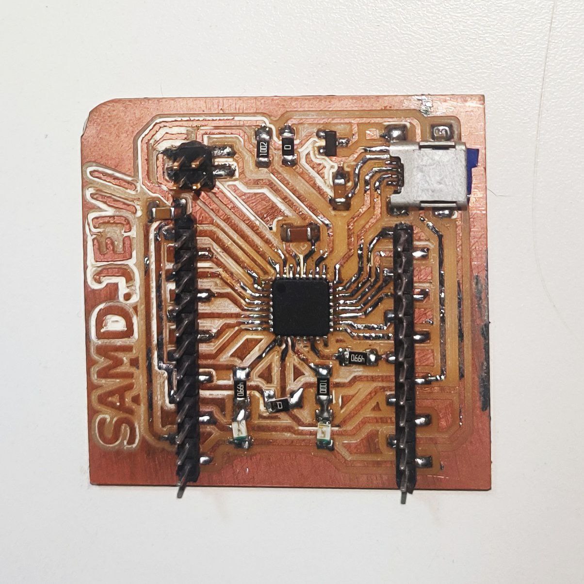
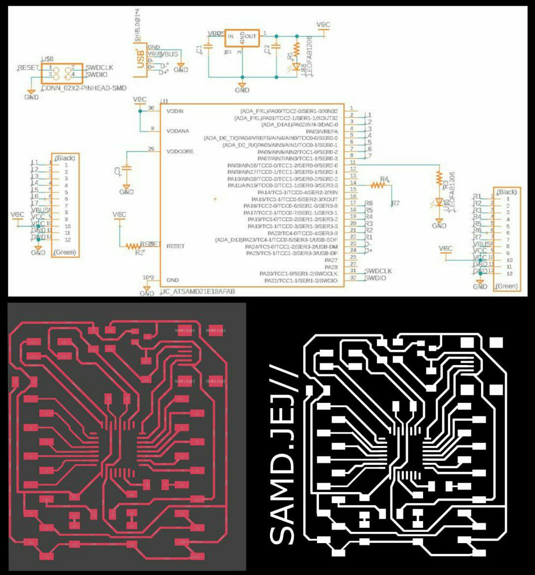 Click here to learn more about the milling and soldering processes.This was the end outcome of my work.
for downloading file Click here
A self-capacitive system detects capacitance variations with respect to the earth ground. In a parallel-plate paradigm, the electrode is one plate of a capacitor, and the other plate is either ground or the user’s finger. A touch increases the electrode capacitance because the human body “adds” capacitance to the system’s capacitance.
- for initial trial i simply by connecting a copper plate or any other conducting material to any of the 6 Peripheral Touch Controller (PTC) pins. we can create a capasitive touch sensor. to find out the variation while tuching the pad i used the below written code.
And the output was we got a value above 1000 when tching the copper plate.
//─────────────────────────────── #include "Adafruit_FreeTouch.h" #define numPads 1 int toucch = 2; //─────────────────────────────── Adafruit_FreeTouch qt[numPads] = { Adafruit_FreeTouch( toucch, OVERSAMPLE_4, RESISTOR_50K, FREQ_MODE_NONE ), }; //─────────────────────────────── void setup() { SerialUSB.begin( 115200 ); for ( byte pad = 0; pad < numPads; pad++ ) { qt[pad].begin(); pinMode(8, OUTPUT); } } void loop() { for ( byte pad = 0; pad < numPads; pad++ ) { SerialUSB.print( qt[pad].measure() ); SerialUSB.print("\t"); delay(500); } SerialUSB.println(); } - I attempted connecting a speaker as an output for the second iteration so that I could play a single note while tapping the pad.
//─────────────────────────────── #include "Adafruit_FreeTouch.h" #define numPads 1 int piezoPin = 23; int toucch = 2; //─────────────────────────────── Adafruit_FreeTouch qt[numPads] = { Adafruit_FreeTouch( toucch, OVERSAMPLE_4, RESISTOR_50K, FREQ_MODE_NONE ), }; //─────────────────────────────── void setup() { SerialUSB.begin( 115200 ); for ( byte pad = 0; pad < numPads; pad++ ) { qt[pad].begin(); pinMode(8, OUTPUT); } } void loop() { for ( byte pad = 0; pad < numPads; pad++ ) { SerialUSB.print( qt[pad].measure() ); SerialUSB.print("\t"); } if (qt[0].measure() > 700) { tone(piezoPin, 549); delay(100); digitalWrite(8, HIGH); } else { digitalWrite(8, LOW); tone(piezoPin, 1000, 500); } SerialUSB.println(); } - as I used SAMD21E17A it has only 6 PTC so i tried controlling multiple pads using single pin
There was a lot of noise, and it was not as successful as I had hoped.
//───────────────────────────────

#include "Adafruit_FreeTouch.h"
#define numPads 2
int piezoPin = 23;
int toucch = 2;
int tb;
//───────────────────────────────

Adafruit_FreeTouch qt[numPads] = {

  Adafruit_FreeTouch( toucch, OVERSAMPLE_4, RESISTOR_50K, FREQ_MODE_NONE ),
Adafruit_FreeTouch( 3, OVERSAMPLE_4, RESISTOR_50K, FREQ_MODE_NONE ),
};

//───────────────────────────────

void setup() {
  SerialUSB.begin( 115200 );
  for ( byte pad = 0; pad < numPads; pad++ ) {
    qt[pad].begin();
    pinMode(8, OUTPUT);
  }
}

void loop() {


  for ( byte pad = 0; pad < numPads; pad++ ) {


    SerialUSB.print( qt[pad].measure() );
    SerialUSB.print("\t");
     }

    if (qt[0].measure() > 250 && qt[1].measure() < 1000  )
    {
      tone(piezoPin, 549);
      delay(100);
      digitalWrite(8, HIGH);
       tb=1;

    }
    else
    {
       tb=7;
      digitalWrite(8, LOW);
      tone(piezoPin, 1000, 500);
    }
    if (qt[1].measure() > 920 && tb != 1 )
    {
      tone(piezoPin, 294);
      delay(120);
      digitalWrite(8, HIGH);

    }
    else
    {
      digitalWrite(8, LOW);
      tone(piezoPin, 1000, 500);
    }


  SerialUSB.println();
}
Joy Stick
-
Here i used a dual axis high quality JoyStick Module and edited potentiometer code to display were the joystick is positioned.
void setup() {

  SerialUSB.begin(9600);
}


void loop() {

  delay(1000);


  if (analogRead(3)> 800)
  {
          SerialUSB.println("Down");
  }
    if (analogRead(3)< 100)
  {
          SerialUSB.println("Up");
  }

   if (analogRead(2)> 900)
  {
          SerialUSB.println("Right");
  }
  if (analogRead(2)< 100)
  {
          SerialUSB.println("Left");
  }
  }
Group Assignment
As a group assignment, we probed a joystick which is basically multiaxis potentiometer where the character of the potentiometer was visualized in the digital oscilloscope.
First the 5V is given from the Programmable DC Power Supply to the joystick and then, first set the oscilloscope to DC supply. Then autoset the oscilloscope. After there is a green liight in the Run/Stop, place the black wire to the ground and the vcc to the vout of the joystick.and red wire to the axis out of the joystick.
Now after the circuits are completed, move the joystick in the connected axis. Here you will notice that the signal is going in a stright line near to 2.5V, there is a gradual change in the position of the signal to 0V or to 5V according to the direction of the joystick. and goes back to 2.5V when the joystick is released.