15. Mechanical design and Machine design
Objectives
Group (To redirect to group assigment page Click here)
- design a machine that includes mechanism+actuation+automation+application
- build the mechanical parts and operate it manually
- actuate and automate your machine
- document the group project and your individual contribution
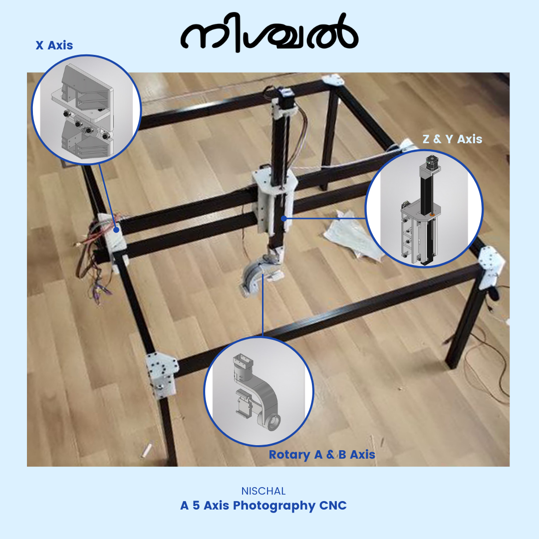
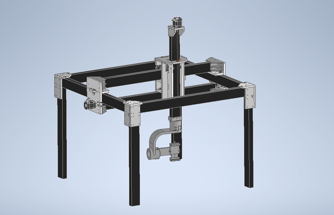
This is the week when we put our key abilities to work and work together to build a machine. We came up with several ideas for the group project, including a car that draws pictures on the floor, a laser projector, a table cleaner, and a robotic arm, among others, and we had a good and healthy discussion about which project to do in order to get the most out of the assignment as well as from team members while also finishing it on time. It’s a good thing we started talking about this before the assignment week. Then we separated into groups based on our strengths and promised to share what we learned as we progressed, making efficient use of time. and finally came to a conclution to make a 5 axis camera robot wich can be used for product photography. The main reason to select this mechanism was we focused more on learning more by adding something more to a existing system.
we went through various process from designing, fabricating, testing, assembly, and most importantly prototyping a lot of mini parts as per designs.
We first talked about how we were going to make it. Timing belts with stepper motors were confirmed for the driving system. Then, as we were talking about what to utilise for the movement, our instructor, Jogin Francis, suggested that we use aluminium extrusion. Then we tried looking for them in the lab, but all we found were remains from our seniors’ project. The design team and the material team began on a search for a 25mm X 50mm aluminium extrusion section. We double-checked that the length and strength were both consistent. We chose aluminium extrusion since it was less expensive and readily available in our area.
works were divided as follows:
-
Different major work assigned is given below.
-
3D designing - Jowshin Emmanuel Johnson
-
Fabrication and testing - Arun Bobby
-
Electronics - Minshad Babu
-
Documentation and milestone keeping - Muhammed Fahiz KP
done our part and then met at assembly. Where all the parts assembled and mechanically tested. and boards were installed and then tested.
Individual Contribution
so as my part was to design the mechanical structure of the machine
Making X granary
main objective of this designe was to make the sliders ourself as comonly used Linear rails couldint be used as our machine is bit large raies are expensive and hard to find localy in our area and the second one was to make the parts millable as 3D printing consumes much more time. bigining with how to hold the frame we started by measuring the size of the extrution and concidered making a 700x700mm bed size.
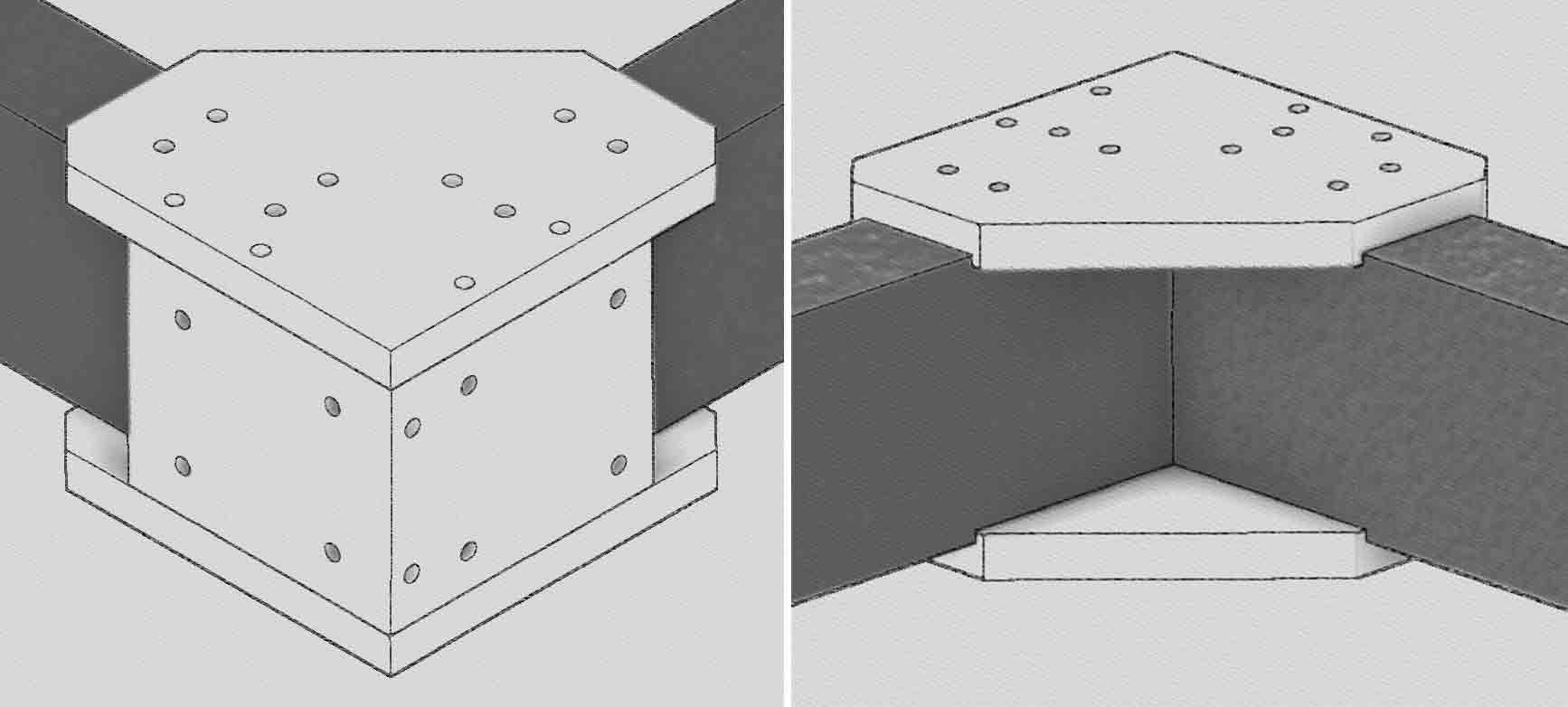
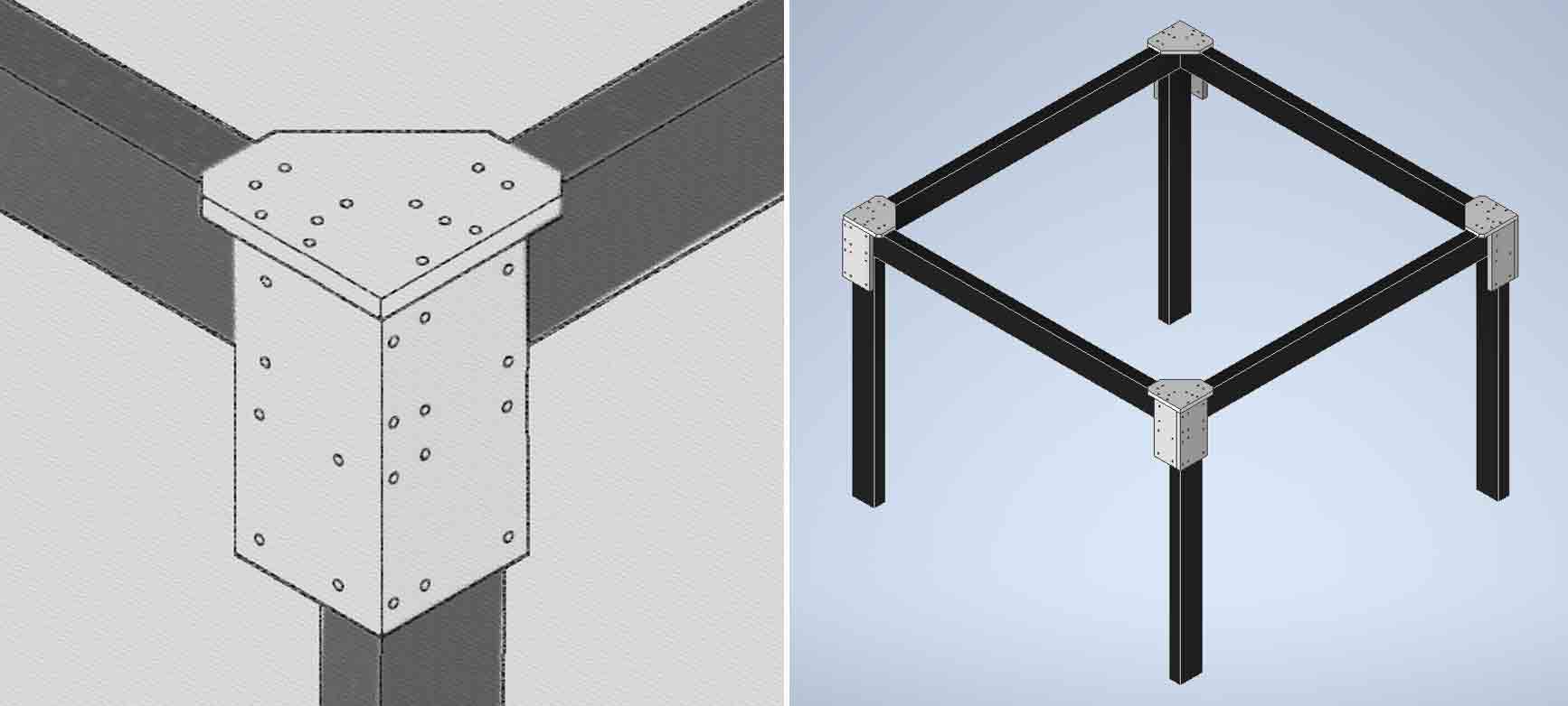
slight change was made and the bottom plate was removed as we needed the frame to be held at a hight and the design for the frame was completed
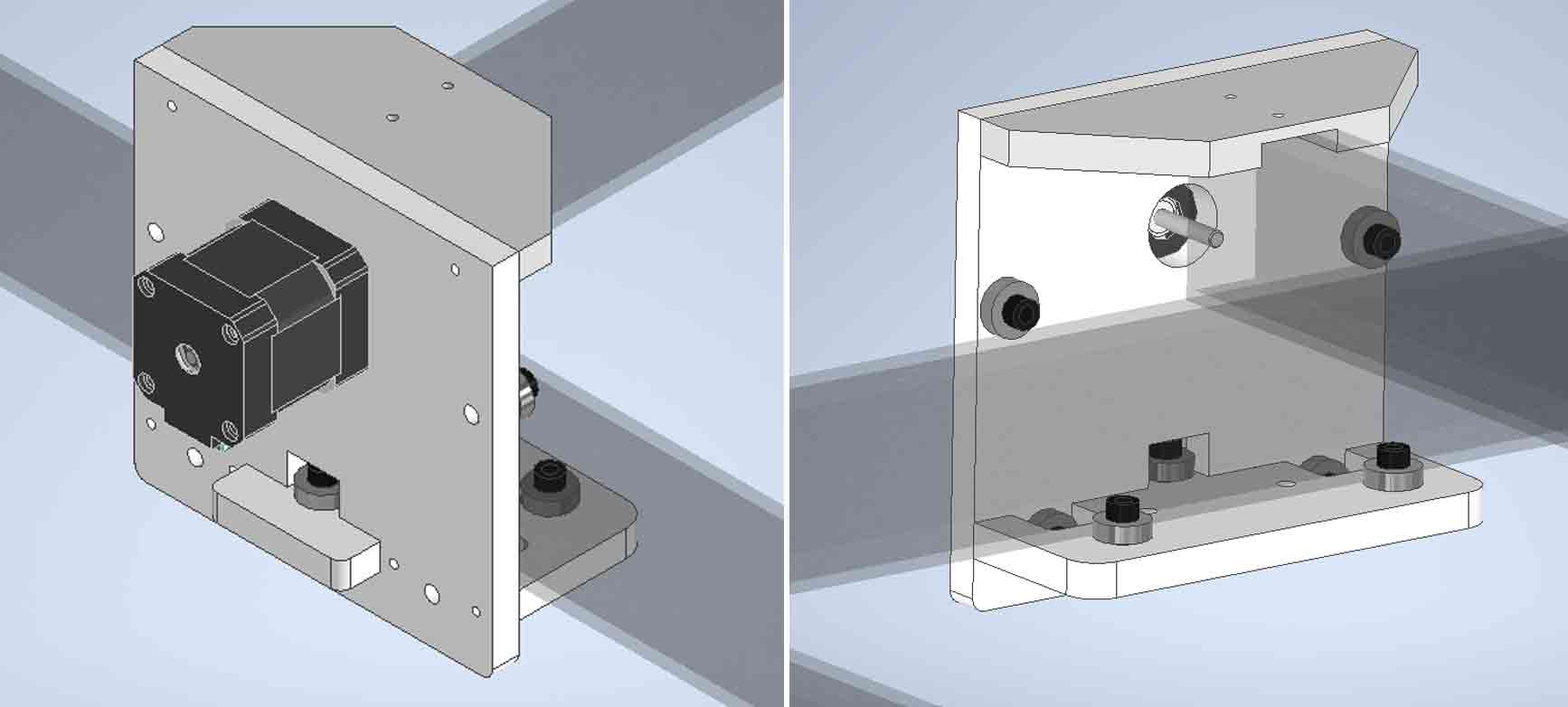
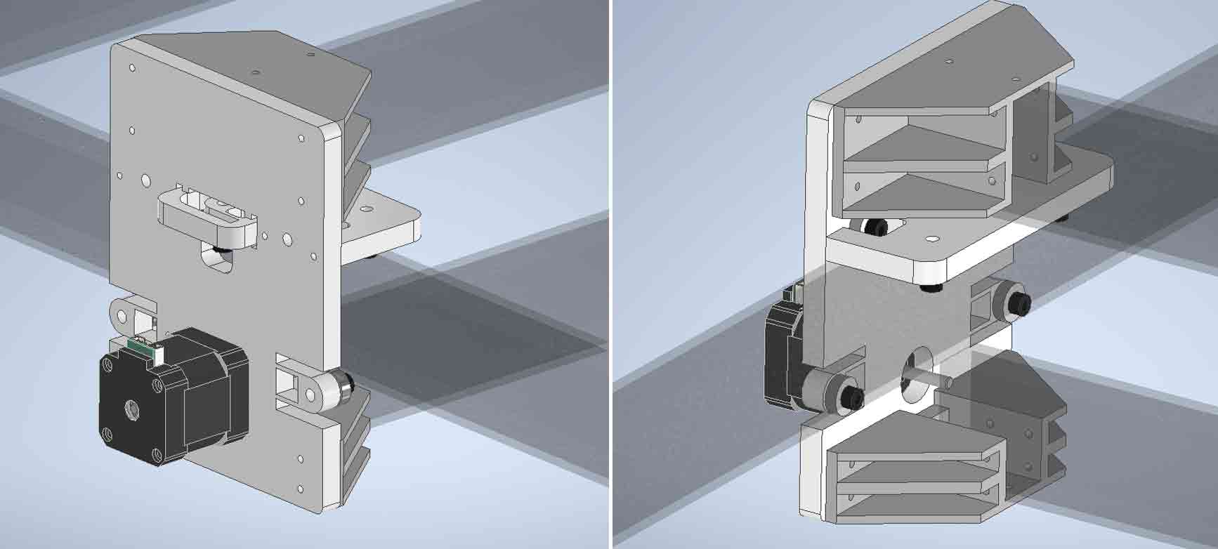
for the x axis my idea was to hold a extrution to move on x asis moving on bearings 4 bearings used on first plate to have smooth motion on one side and 3 on the other plate the design was created
 but realising that the design mght not work as we thought due to the uneven dimention of the extrution and as the z ganery want to suport a bit of a weight our instructer Jogin Fransis suggested to give 2 channels over y azis insted of 1 and asked me to refer our senior batches project wich had a simple flecture mechanism to overcome the problem with the uneven surface so I adapted their tested sucessful flecture mechanism on to ours.we also changed the holding mechanism to 3D printable design as it has a better holding capablity than the former design.
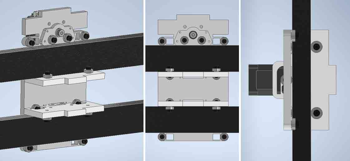
 so now it was time to test the slider for x ganary me and Arun with Jogins assistence milled Polypropylene plastic(PP) in Zund
then the milled out parts were assembled and tested with Aruns help and the part was working fine and we called it a day.
we measured dimention of the belt and made a mechanism to drive the axis using the belt for which the belt was firmly held between 2 bearings and the channel by giving a clearence between the channel and bearing
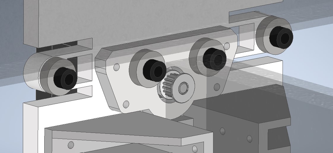 which while testing was failed as the belt was slipping away from the bearing while the motor was running.
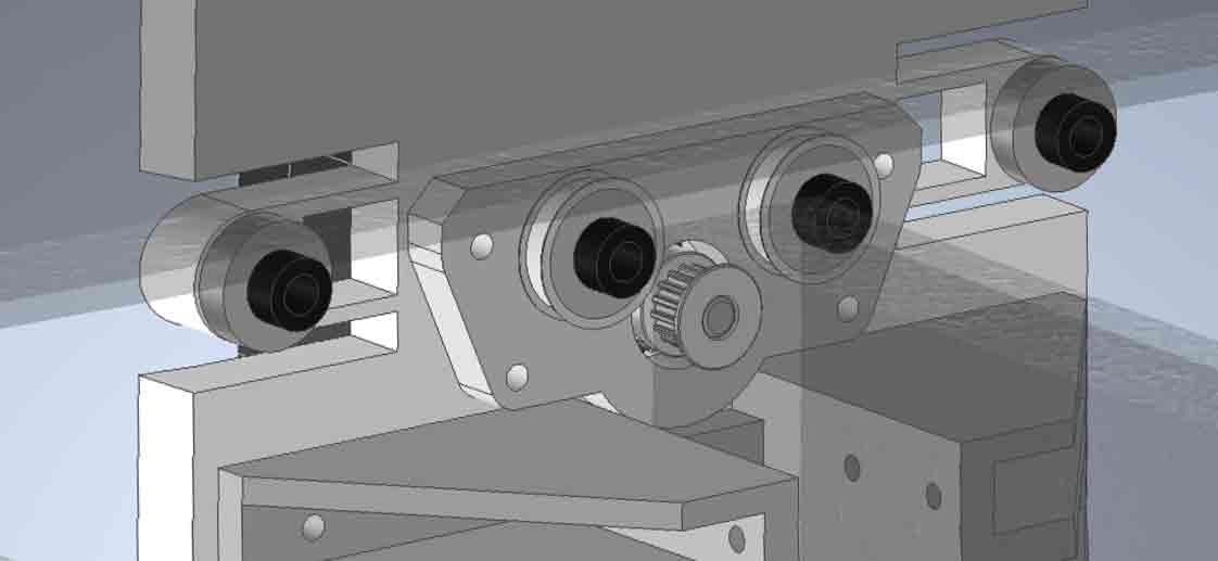 the part was 3D printed and tested.
Making Y & Z axises
This part was actually quite easier because we had tested and confirmed the designe aspects so used the same mechanism used in x asis and for z asis we desided to use leadscrew mechanism started with y slider. 8 bearings fro holding on the 2 channels and 6 for the othe pices.
 now for Z axis a lead nut was installed inside the top plate for actuating the z axis motion and a total of 10 bearing was used to make clear sliding motion to the z axis
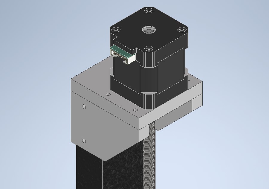
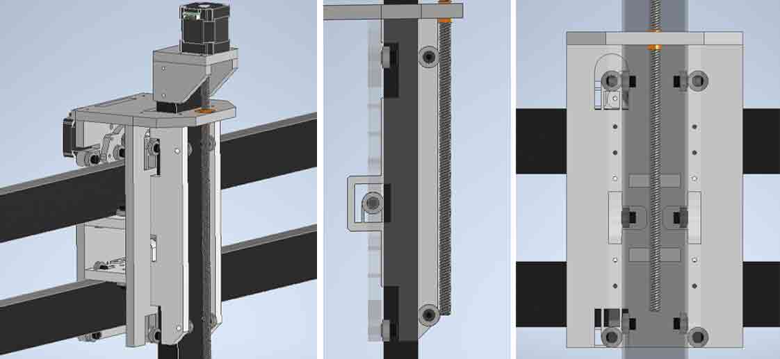 and a structure for holding the steper was made and fixed on the top of the z axis channel
 the A and B axises were designed by Arun Boby and compined with my part to complete the whole design.
Click here to learn more about 3D modeling.
the A and B axises were designed by Arun Boby and compined with my part to complete the whole design.
Click here to learn more about 3D modeling.
 for downloading file Click here
Now the design is ready to be milled
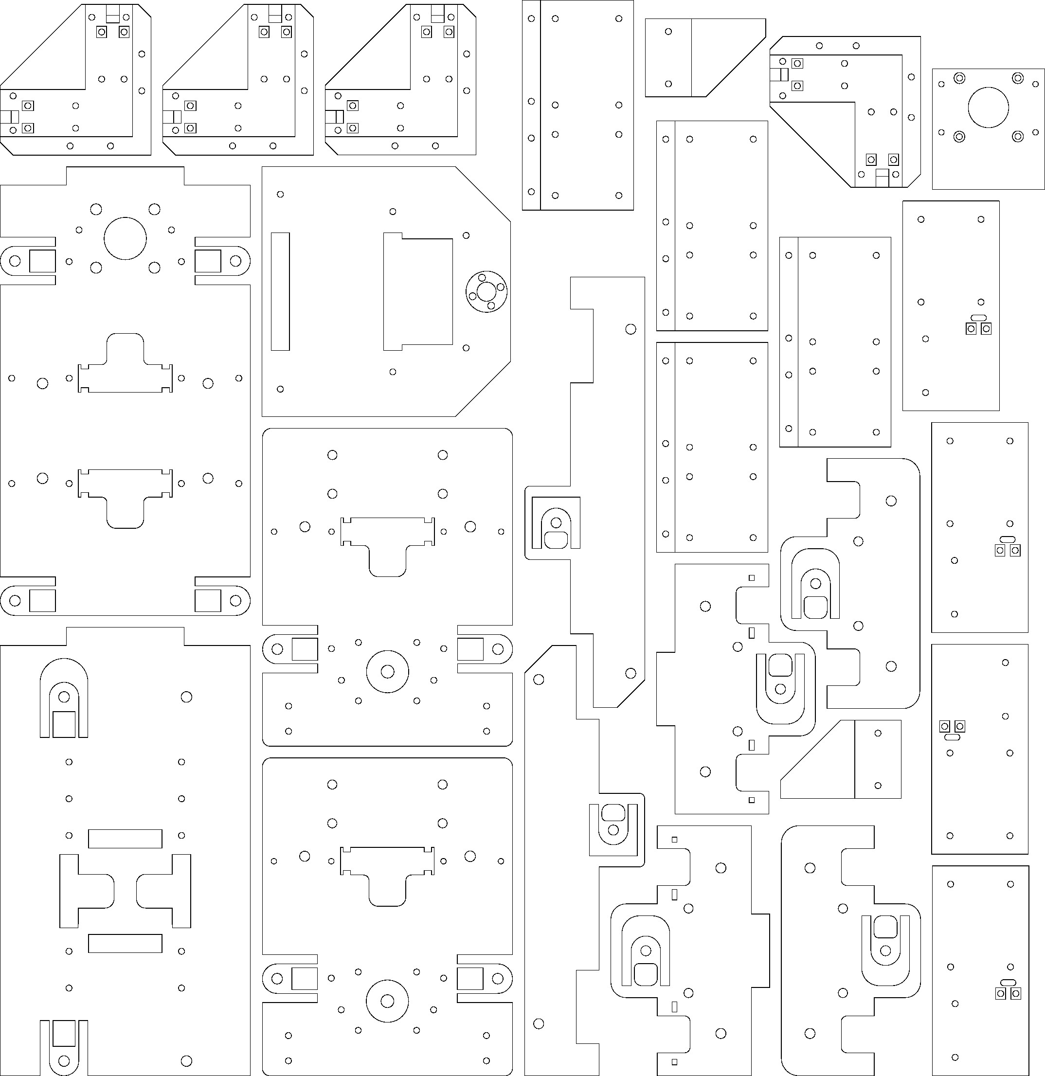 for downloading file Click here
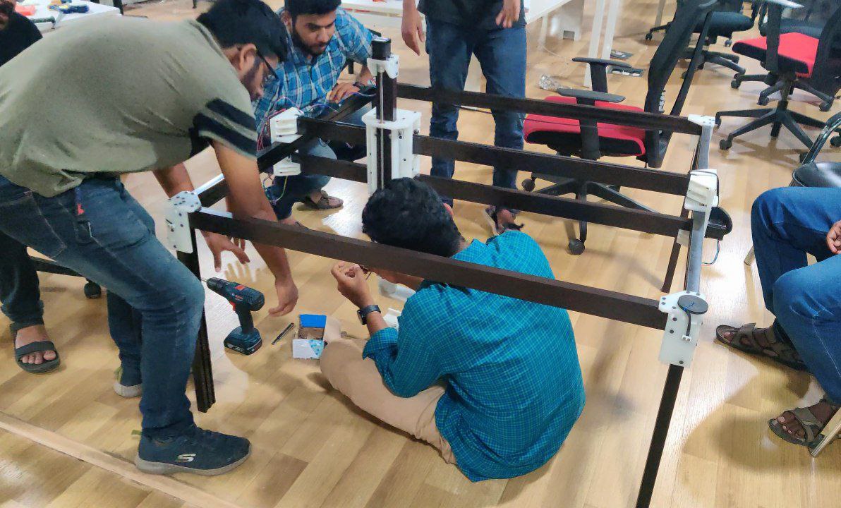
finally all part were milled out and we assembled the mechanical structure together and finally the mechanical structure was handed over to electronics amd programming.
 to know more about the left of the project redirect to group assigment page Click here