Networks and communications
In this week we have two missions:
Group assignment: This consists of sending a message between two projects.
Individual mission: It consists of designing, building and connecting wired or wireless nodes with network or bus addresses.
Individual mission
During this week, for the individual mission I was interested in the WIFI module ESP-WROOM-02. The goal is to send a message from a trash can to a user or household manager. That is, when the bin is full, instead of the user calling or signaling the household manager, the trash can automatically locks and alerts the household manager. Thus, once the message received it passes for the dump. To achieve this I divided my work into several such as:
- Design and assembly of my PCB;
- Communication and networking;
- Programming and testing.
ESP-WROOM-02D
ESP-WROOM-02D and ESP-WROOM-02U are modules based on ESP8266EX developed by Espressif. Compared to ESP-WROOM-02, the RF performance of ESP-WROOM-02D and ESP-WROOM-02U is optimized. In addition, for our work we used ESP-WROOM-02D.
The ESP8266EX incorporates a 32-bit RISC Tensilica L106 processor, which achieves very low power consumption and reaches a maximum clock speed of 160 MHz. The real-time operating system (RTOS) and Wi-Fi stack provide 80% of the processing power for programming and user application development. The CPU includes the interfaces as below:
- Programmable RAM/ROM interfaces (iBus), which can be connected with the memory controller, and can also be used to visit the flash;
- Data RAM interface (dBus), which can be connected with the memory controller;
- AHB interface that can be used to visit the registry.
The photo below shows the pin distribution of the ESP-WROOM-02D.
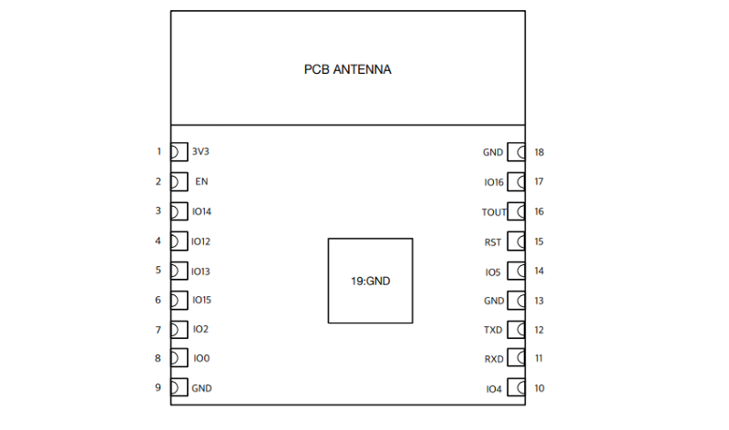
Top view
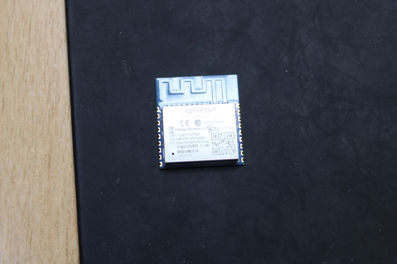
ESP-WROOM-02D
PCB Design
To design my PCB I used Eagle Autodesk.
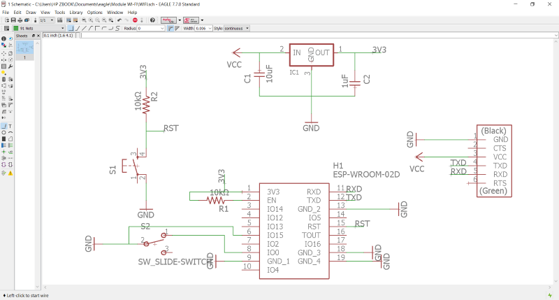
Schematic
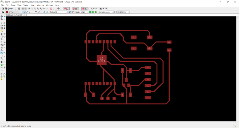
Board
Assembly
List of components
| Designations | Components | Refernce |
|---|---|---|
| WIFI module | ESP-WROOM-02D | |
| Capacitor | Ceramics | 1 μF and 10 μF |
| Resistor | SMD | 10 kΩ*2. |
| Voltage regulator | Header SMD | 3.3v |
| Connector | FTDI | 2X3 |
| Connector | FTDI | 2X3 |
| Switch | ||
| Slide switch SDPT |
These photos represent the weld.
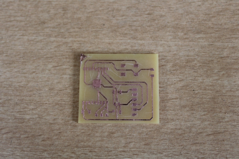
PCB after milling
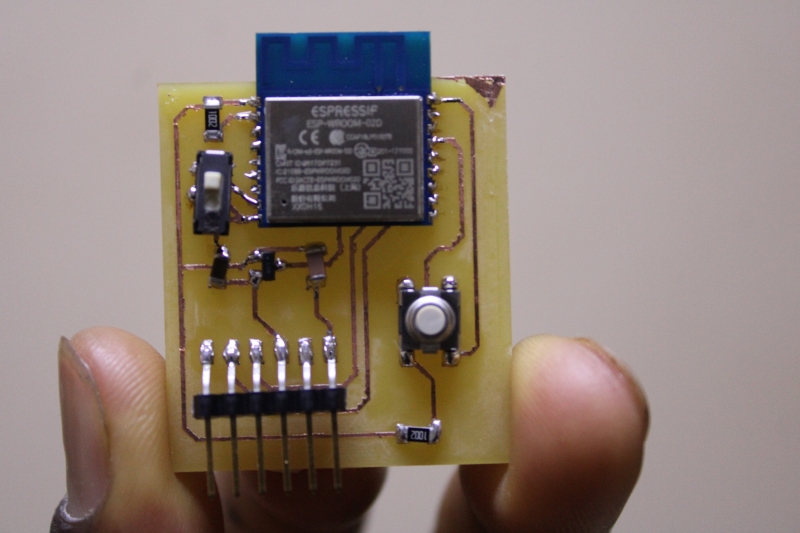
Circuit after welding
Program and test
In this part, I used the Arduino IDE to write code and test my WIFI module. As I had no experience in using WIFI module I had to go to this site https://randomnerdtutorials.com/how-to-install-esp8266-board-arduino-ide/ to be able to understand some things. So I copied the link from the ESP8266 in order to download it to my Arduino IDE.
Program
#include
#include
#include
#define APSSID "ESPap"
#define APPSK "thereisnospoon"
#endif
/* Set these to your desired credentials. */
const char *ssid = APSSID;
const char *password = APPSK;
ESP8266WebServer server(80);
/* Just a little test message. Go to http://192.168.4.1 in a web browser connected to this access point to see it.
void handleRoot() {
server.send(200, "text/html", "
You are connected
");}
void setup() {
delay(1000);
Serial.begin(115200);
Serial.println();
Serial.print("Configuring access point...");
/* You can remove the password parameter if you want the AP to be open. *//* You can remove the password parameter if you want the AP to be open. */
WiFi.softAP(ssid, password);
IPAddress myIP = WiFi.softAPIP();
Serial.print("AP IP address: ");
Serial.println(myIP);
server.on("/", handleRoot);
server.begin();
Serial.println("HTTP server started");
}
void loop()
{
server.handleClient();
}