COMPUTER-CONTROLLED MACHINING
This week's mission is to design something big using one of our LAB's CNC machines. But before the design of our part we must first test the capabilities of the machine to make false circles, alignment, its operating speeds, advances and tool paths. For our part we used ShopBot PRSalpha. In addition to the ShopBot we have two vacuum cleaners namely Shop Fox and Shop-Vac. They facilitate the work of the machine by sucking projectiles from the wood or cut material. It has high performance, high volume, speed and reliable power for all cutting stains.
ShopBot
Characteristics
XY Move Speed (with full cutting force): variable, max. 720"/min
Z Move Speed (with full cutting force): variable, max. 360"/min.
XY Positioning Speed: Variable, max. 1800"/min.
Z Positioning Speed: Variable, max. 900"/min.
Step Resolution: 0.0004".
Positional Repeatability: +/- 0.002".
X and Y Axis Drive System: Rack and Pinion.
Z Axis Drive System: Rack and Pinion.
Z Input Voltage: 220v single-phase, 230v 3-phase and 380/460V 3-phase power options are available, depending on tool and configuration.
0004" step resolution.
Positioning accuracy of +/- .002".
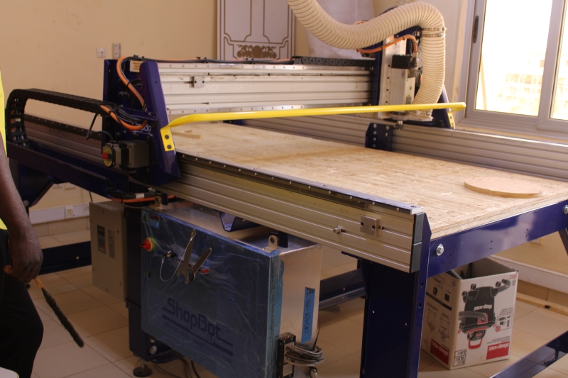
ShopBot
Shop Fox
It allows to suck the projectiles of the cut material during the operation of ShopBot. It is very important when you want to cut something big. But it is very powerful and consumes a lot of electrical energy so you can't use it when you want to cut something small.
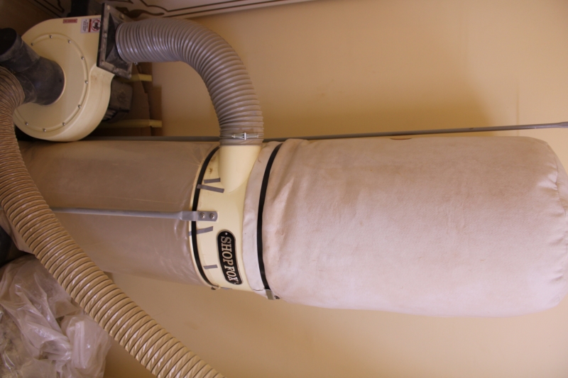
Shop Fox vacuum cleaner
Shop-Vac
Shop-vac is our second vacuum cleaner. Unlike the first one above we use it when we want to cut a small object. It is not as powerful as its and it consumes less electrical energy. The advantage of this vacuum cleaner is that it is movable.
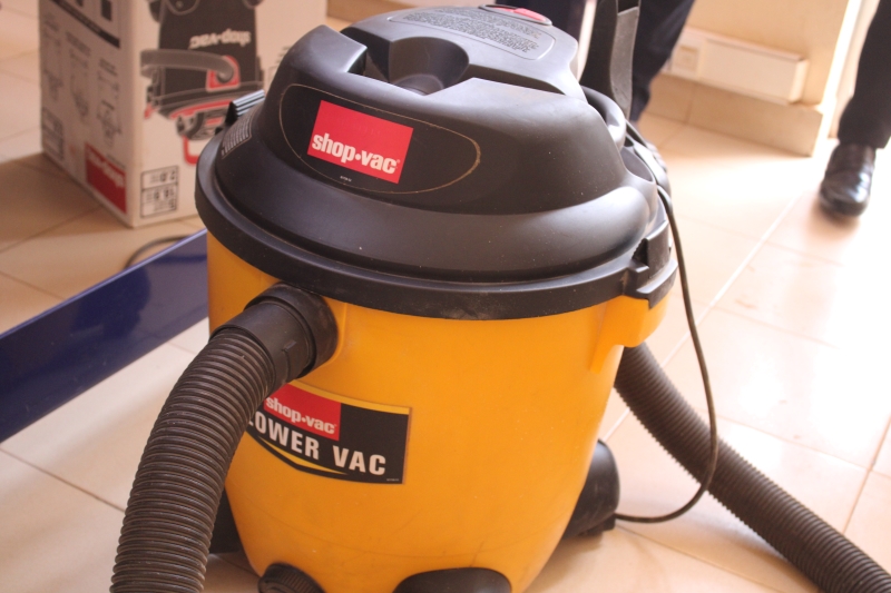
Shop-vac vacuum cleaner
Cutters
To be able to work with ShopBot we used several types of cutter. Among the different types of cutter we end mills, Ball Nose and V-Bits
- End Mills: End Mills are strawberries that allow you to cut and engrave objects. They are more used for 2D objects and they have a flat head.
- Ball Nose: Unlike the End Mills, they have a round head. They allow you to cut or model 3D objects. They make it possible to design smooth 3D objects.
- V-Bits: They are from the group of V-shaped strawberries. They make it possible to chamfer objects. In our FAB we have the one that chamfers at an angle of 45 °.
These images represent the different cutters
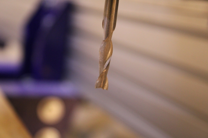
End Mills
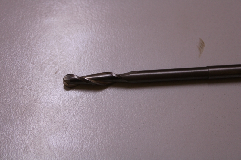
Ball Nose
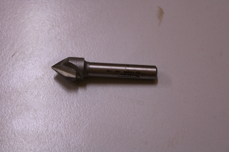
V-Bits
In this image we have an End Mills cutter that allows planing over a large area.
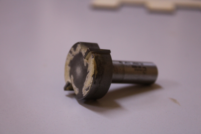
Ends Mills cutter for rabo
Safety and precautions
The machine is very with a powerful high rotational speed. So before doing anything on the machine we will first take certain precautions in order to protect ourselves and the machine. For this we will need:
- A glove or protects. When the wood is not cut well, the debris of the woods can hurt us if we want to remove the wood from the tray with our bare hands;
- Glasses. As the machine spins at a high speed the projectiles of the pieces of wood can injure our eyes;
- Headphones: The machine makes a lot of noise when it is running especially when you want to cut something hard or heavy like iron and hardwood;
- Check the supply voltage.
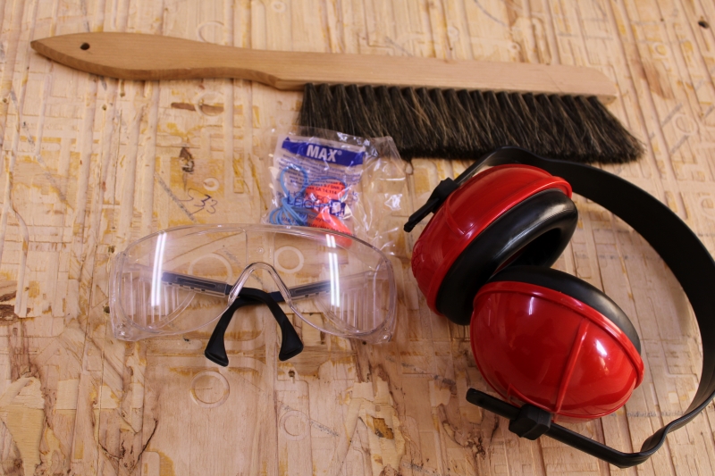
Protective equipment
Group assignment
In this part of our work we performed different configurations of the machine for the different tests. Among these tests we have the false round, alignment, speeds, advances and tool paths. We used SolidWorks for the design. As configuration software we used Aspire as in the previous mission
1. Test runout
In this part of our work, we checked if the Z axis was straight. When the Z axis is offset it plays on the alignment that we have discussed below. For this we made several cuts with several machines such as Epilog Laser and Modela MDX-50 and compared the different cuts.>
The images below represent the different cuts.
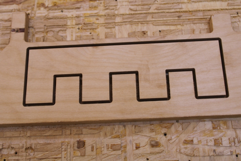
ShopBot cut
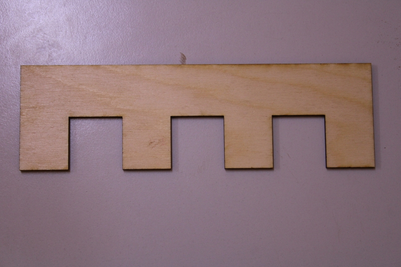
Laser cut
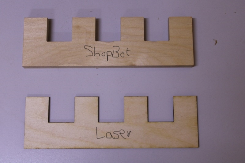
On this image we have ShopBot cut above and Laser cut below
2. Alignment
This task involves cutting an object rectangular, square, or circular to see if the object still keeps the same shape. For the cut we chose a 6mm End Mil cutter, a speed of 12,000rpm, a pitch of 20mm/min and a depth of 20mm/min. Before we started cutting we replaced the 3mm cutter that was already there with a 6mm cutter.
To be able to change the cutter we needed a 27mm wrench and a collar wrench. The collar wrench is positioned on the left and the 27mm wrench above on the right. In order not to provide much effort we have reduced the gap between the two keys. When the gap between the two keys is large it is difficult to loosen the strawberry door.
The images below show us how to change cutters.
This image represents the different cutters.
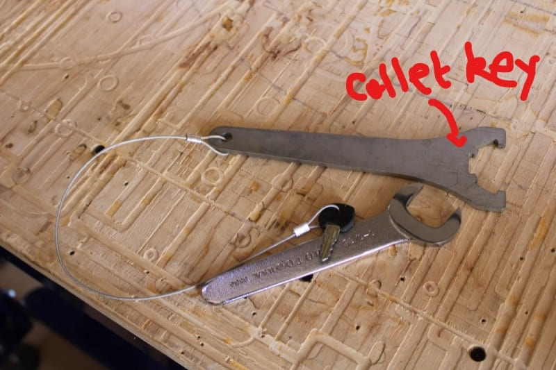
Cutter changing tools
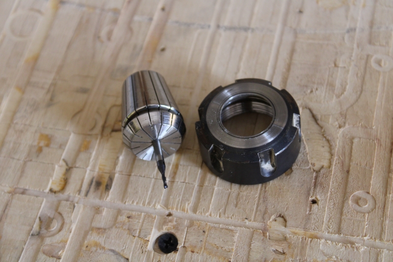
Cutter holder
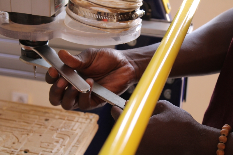
Cutter change
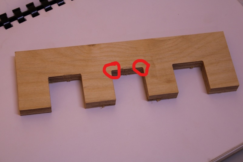
After cutting, we found that the circled areas were rounded. However the cut was good because the cut part was smooth and straight. So we concluded that the machine has a good linear cut. In addition, we had a good measure. This allowed us to confirm that it also has a good runout.
The image above shows us the measurement made.
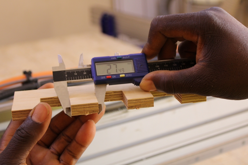
Measure
This image show how the machine cannot cut at a 90° angle.
Object
3. Speed, advance and toolpath
The purpose of this task is to test the accuracy of the machine by playing on its spindle speed, dive rate and movement speed. For our tests we used an End Mills cutter. We used different sizes of cutters for testing. For the tests we focused more on Raster and Offset.
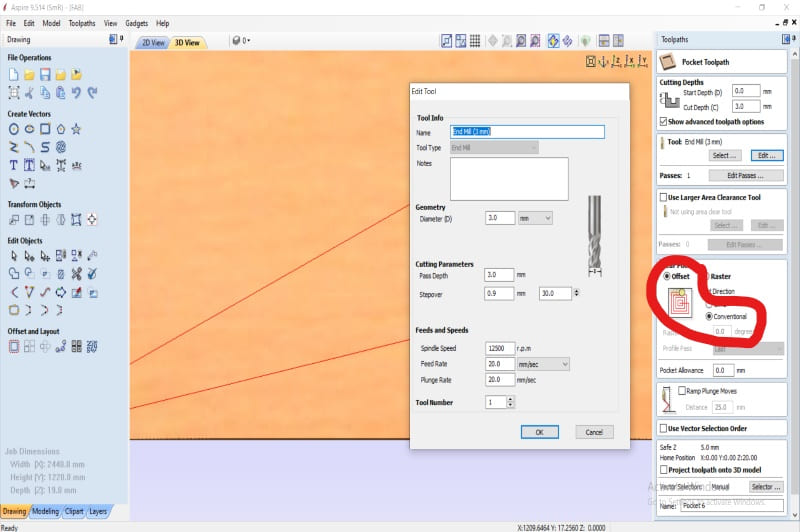
RASTER
In this part we have tested the two directions namely climb and conventional. As a cutter we chose a 03mm cutter. Engraving at the raster level is done linearly. But we did not see any difference between the different engravings.
In the following photos we have the configuration part circled.
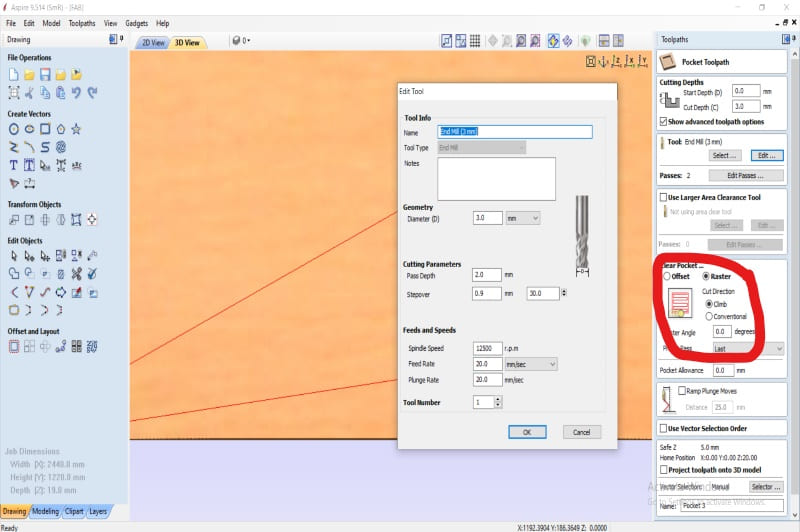
Raster climb
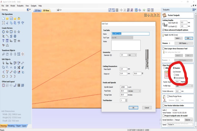
Raster Conventional
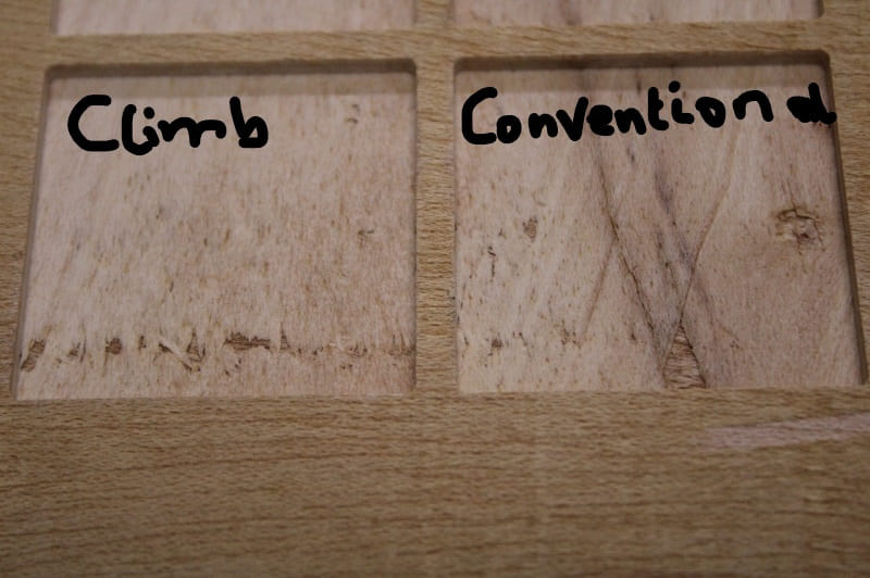
Engraved plywood
OFFSET
Unlike Raster, Offset is circular or square. It starts at the middle point and ends outside. Here we also tested climb and conventional. As raster the results were the same.
In the following photos we have the configuration part circled.
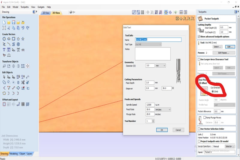
Offset climb
Offset Conventional
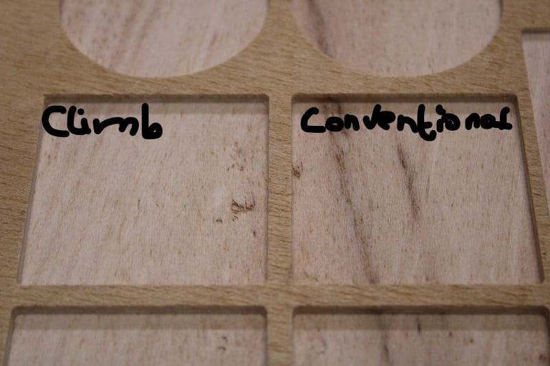
Engraved plywood
CUT
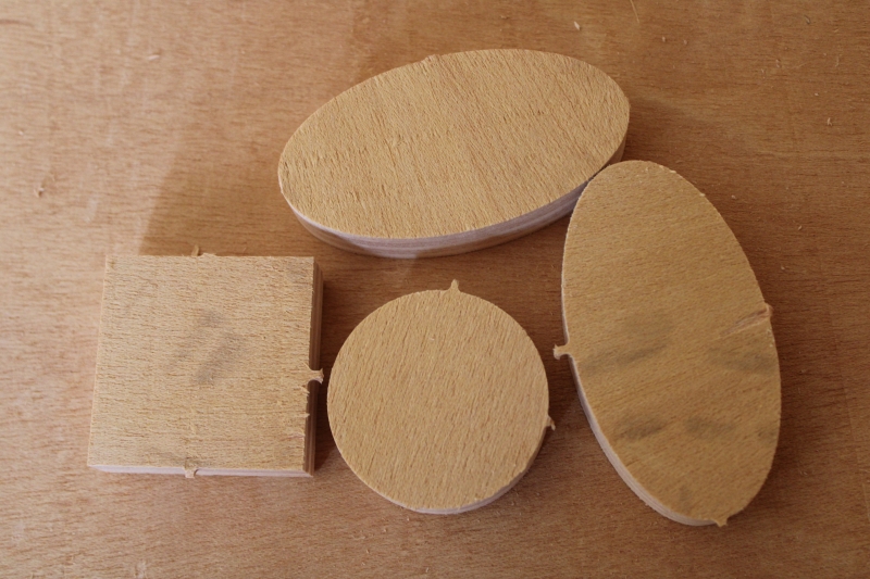
Here we have made several rectangular, circular and oval cuts with different speeds. But even with the maximum speed we noticed that the machine cuts with precision.
Here we had not yet removed the objects after the cut.
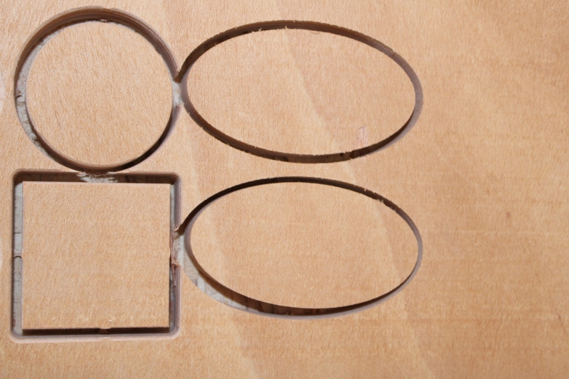
Fixed object
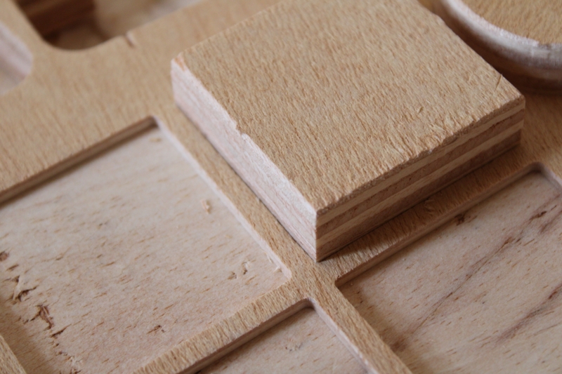
In this image the objects are outside.
Object after cut
In this image we wanted the object in the engraved part.
Final test (Normal fitting.)
Individual Assignment
In order to put the tests into practice we decided to cut something big and assembled. In this part of our work we will therefore confirm the different tests. As a big thing we have chairs, tables, kitchen, etc. But what can we achieve that will be beneficial and use in our LAB? This is how the idea of creating supports for the video conferencing equipment of our LAB came to us. As this is a big project we decided to decide between the tasks. My mission was to create a support attached to the wall that will allow to hang the Camera and the Display Hub. For this we needed plywood. Fortunately for us we already had it.
Design
In this part we thought about how to have not only a good model but also easy to use. So I used SolidWorks to get the model I wanted.
I started by drawing the different parts of my object namely the back, sides and supports of the middle. After that I moved on to assembly. On the photos below I will present you the different and the final assembly.
The image above shows the 3D model object on SolidWorks.
Here I had not yet started to assemble
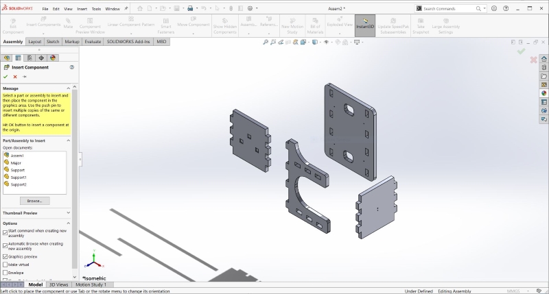
Unassembled design
Assembly complete
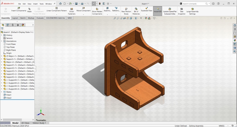
Assembled design
This image represents the rendering
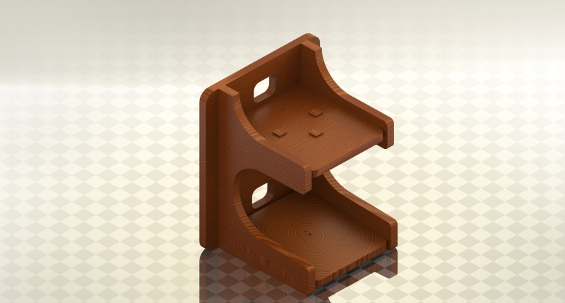
Render
Toolpath generation
Before generating the trajectory of the tool I first exported my DXF file to Vcarve. Seeing that this is a cut I want to make, I went to Toolpaths and chose Profile. For this I used an End Mills cutter of 3mm, 12500rpm as spindle speed and 40rpm as Feed Rate.
For the engraving it is the same procedure but this time I chose Pocket. The images below represent the cutting and engraving tool paths.
Layout of part on Vcare
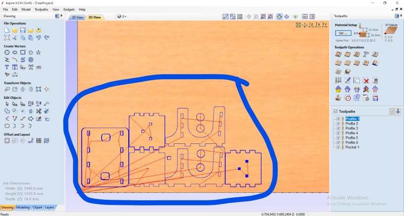
Part
Tool path for cutting
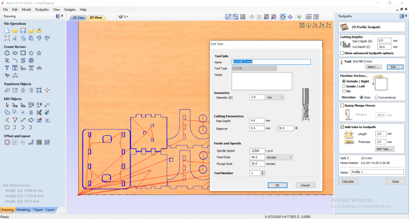
Cut
Tool path for engraving
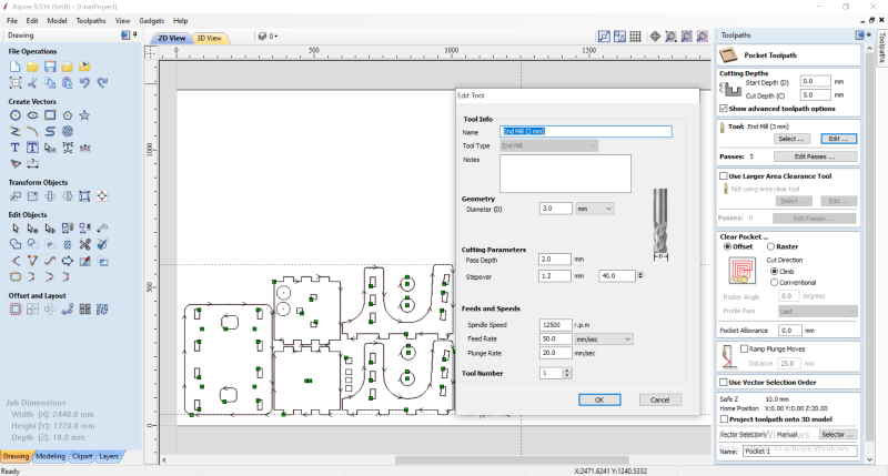
Engraving
Setting up the machine
Before starting the cutting I first positioned the plywood I chose for the cut and finally perform the installation of the machine. But it should be noted that I had a hard time using the plywood because it was not straight because of its poor conservation. For the setting up of the machine, I started with the control of the XY axis and ended with the Z axis. For the Z axis I used the Z axis measurement tool.
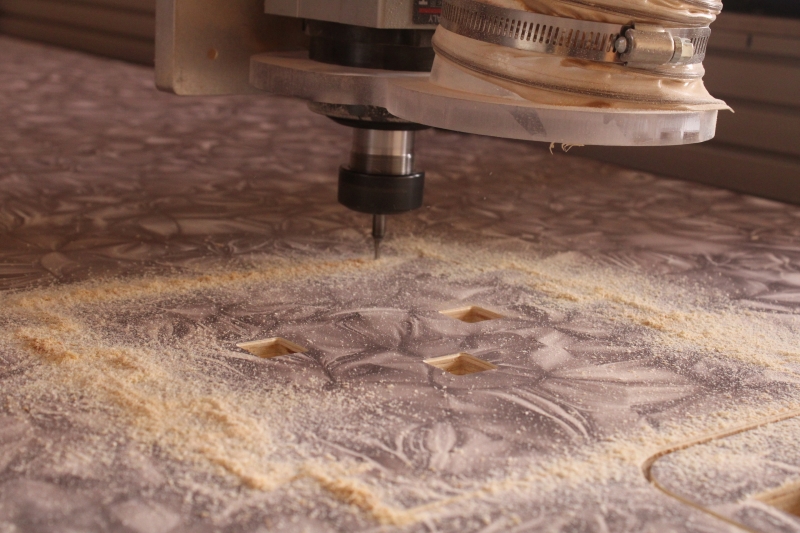
For the engraving it is the same procedure but this time I chose Pocket. The images below represent the cutting and engraving tool paths.Once the control of the Z axis was finished I went to the cut. In the photo we see the wooden projectiles because I had not turned on the Fox vacuum cleaner.
Once the control of the Z axis was finished I went to the cut. In the photo we see the wooden projectiles because I had not turned on the Fox vacuum cleaner.
This photo shows the Z-axis measurement.
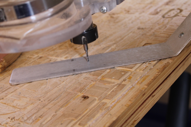
Measurement of the Z axis.
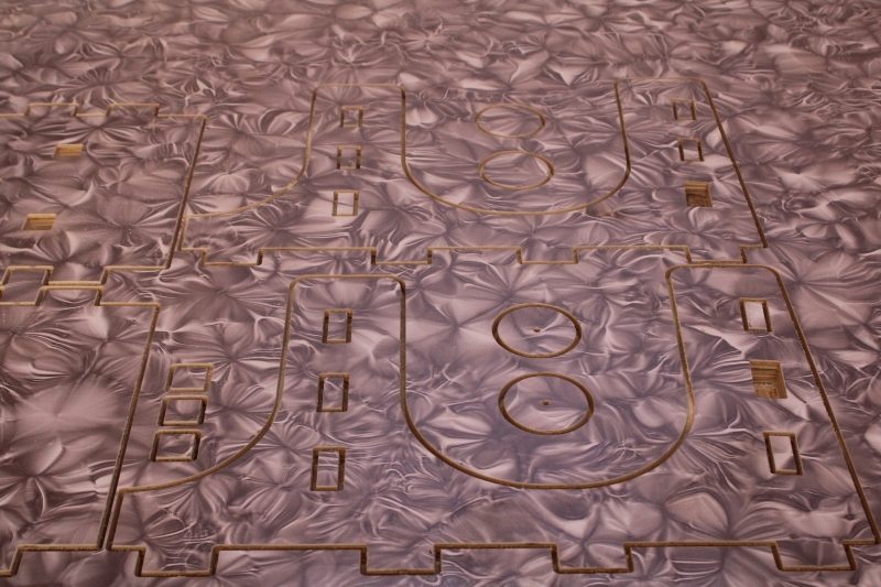
The beginning of machining.
Machining
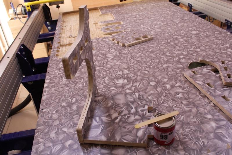
The parts are not yet removed.
End of machining
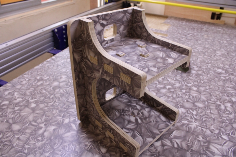
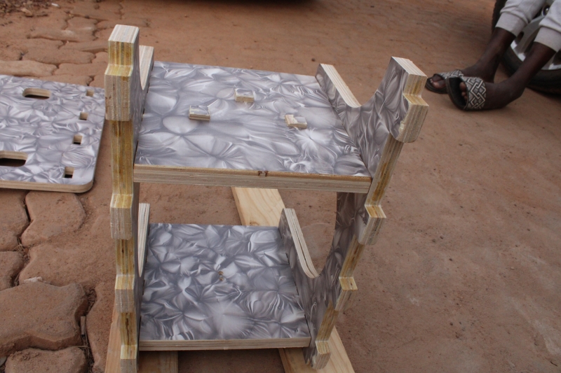
Assembly
Once the machining was finished I started the assembly in order to obtain the final object. So I started by assembling the left piece and the two middle pieces. Then I added the right piece and finish with the back room. So that the parts could join well I used a collar to reinforce the interlocking of the parts between them.
The images above represent the different stages of assembly.
First assembly
Second assembly
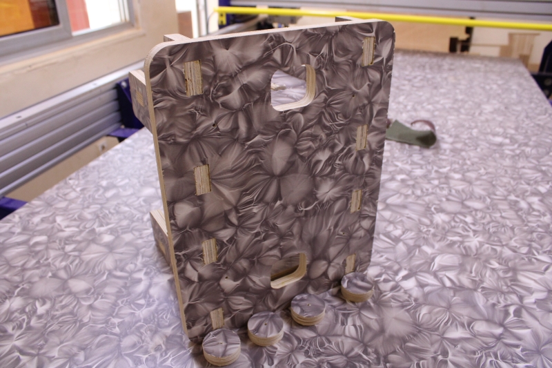
Back