Input devices
Weekly missions
This week I must:
- Probe the analog levels and digital signals of an input device;
- Measure something: Add a sensor to a microcontroller I designed.
This week, we focused on input devices. Input edges are a device used to deliver data and signals to a microcontroller. These devices, called sensors, respond to a physical stimulus (such as heat, light, or sound) and transmit an electrical signal.
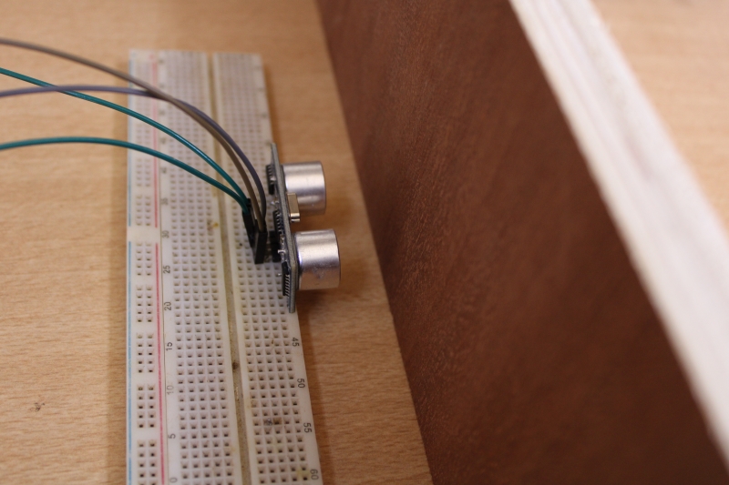
For this week, I first decided to study a GPS module, which is related to my final project. Unfortunately, I had trouble finding the module so I decided to study the Ultrasonic sensor.
HC-SR04 Detection Module
It is a module that makes it possible to evaluate the distances between a moving object and obstacles. It is composed of a transmitter and a receiver. It offers an excellent non-contact detection range, with high-precision and stable measurements. Its operation is not influenced by sunlight or dark materials, although materials like clothing can be difficult to detect.
Characteristics according to the datasheet
- Dimensions : 45mm*20mm*15mm ;
- Measuring range: 2cm to 400cm;
- Measurement resolution: 0.3cm;
- Measuring angle: 15°;
- Pulse drops on the trigger input: 10 μs.
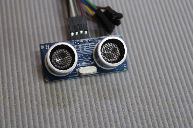
Front
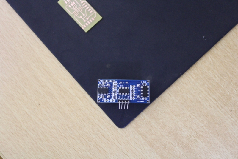
Back
Principle of operation
For a simple explanation, I can say that the transmitter sends a series of sound pulse at 40kHZ a frequency inaudible to the human ear. And if it encounters an obstacle in its path the signal is reflected and returns in the form of an eco-receiver.
In order to measure the distance, the trigger must be in the high state for 10 μs. This will send a sonic burst of 08 cycles that will move at the speed of sound and be received in the Echo pin. The Echo pin will emit a signal when the sound returns.
The measurement of the delay time between sending and receiving makes it possible to indicate the distance of the object. Knowing that Travel time = 2*Distance / Speed and that the speed of sound in the air is about 340m/s.
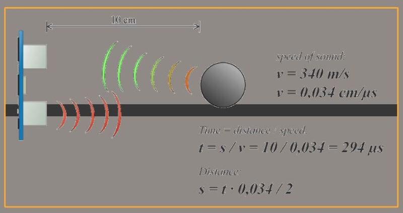
Principle function
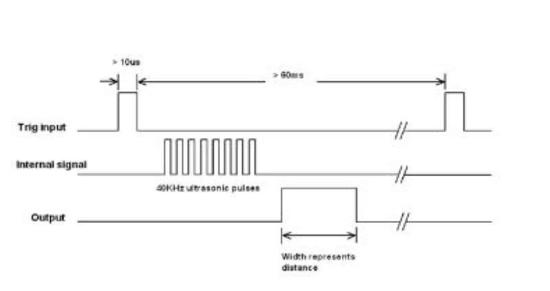
Pulse
Design phase
For the design of the circuit, I used Autodesk Eagle.
The photo above shows the wiring diagram.
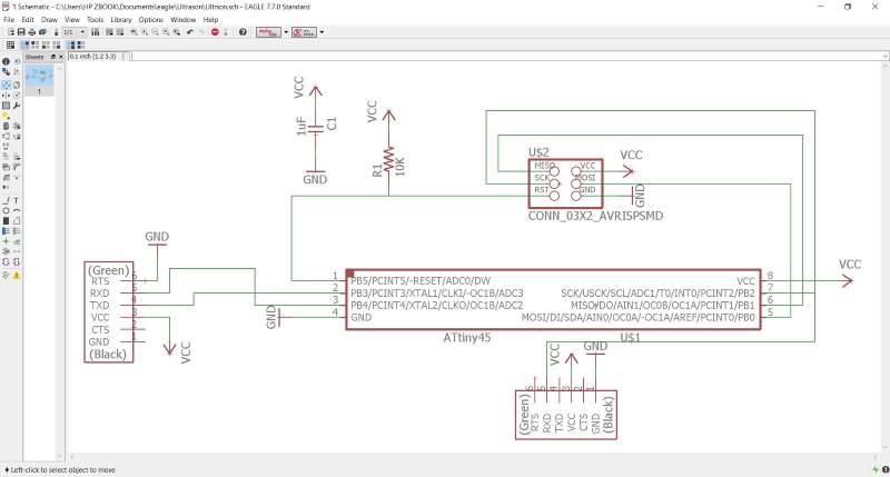
Schematics
This photo represents the imported PNG image.
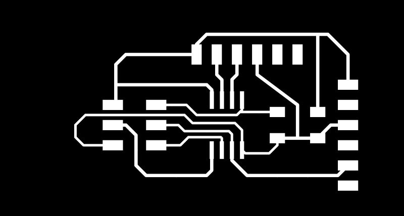
Board
Assembly
In this part of our work, we have welded the different components.
List of components to use
| Designations | Components | Refernce |
|---|---|---|
| Microcontroller | ATTINY 45 | |
| Capacitor | Ceramics | 1 μF 30V |
| Resistor | SMD | 10 kΩ. |
| Connector | Header SMD | 2X3 |
| Connector | FTDI | 2X3 |
This image shows the weld.
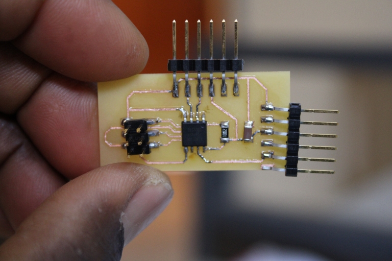
Final circuit
Program and test
In this part, I used the Arduino IDE to write code and test my sensor. To be able to upload the program in on the printed circuit above I have my USBtinyISP.
However, I could not upload the program because the ATtiny 45 I used does not have serial ports, so do not take into account the Serial function of Arduino. So, I went on to use the Arduino module to program my sensor.
Program
int PinTrig = 8;
int PinEcho = 9;
long time;
float vitesse = 340.0;
float distance;
void setup() {
pinMode (8, OUTPUT);
pinMode (9, INPUT);
digitalWrite (8, LOW);
Serial.begin (9600);
}
void loop() {
digitalWrite (8, HIGH);
delayMicroseconds(10);
digitalWrite (8, LOW);
//time calculate
long time = pulseIn(9, HIGH);
if (time > 25000){
Serial.println("Measurement failed");
}
else {
time = time/2;
float distance = (time*340)/10000.0;
Serial.print("Distance: ");
Serial.print(distance);
Serial.print("cm");
}
delay(1000);
}
Test
Measurement results over a range of 2 to 50 centimeters
To begin with I aligned the sensor and the obstacle. The sensor is centered on the center of the obstacle surface and the two are well perpendicular. When taking the measurements I could not go below 2cm.
At the end I found that the average error on the range from 2cm to 50cm is 0.21cm.
| Distance in cm | Measurement in cm | Error in cm | % error |
|---|---|---|---|
| 2 | 2.18 | 0.18 | 18 |
| 10 | 10.23 | 0.23 | 23 |
| 15 | 14.48 | 0.52 | 52 |
| 20 | 19.96 | 0.04 | 4 |
| 25 | 24.96 | 0.04 | 4 |
| 30 | 29.95 | 0.05 | 5 |
| 40 | 39.97 | 0.03 | 3 |
| 50 | 49.62 | 0.38 | 38 |
The image above represents the minimum possible distance.