ELECTRONIQUE DESIGN
This week's mission is to make an electronic circuit using the equipment we have in our LAB. Before getting into the topic bus, we will first define the electronic design. An electronic circuit is a path of conductors through which electric current can flow. An electronic circuit includes:
- One or more power supply circuits;
- One or more inputs and one or more outputs;
- Componnents:
- Passive (resistor, capacitor, coils, etc.);
- Active (diode, transistor, triac, integrated circuit, microprocessor, microcontroller, etc.).
1. Power supply circuit
An electrical circuit is a set of electrical or electronic components, including conductors, traversed by an electric current. In an electrical circuit we have the appearance of quantities such as current (in amperes), voltage (in volt) and resistance.
2. Entry and exit
On calls the exchange of information between the processor and its associated devices input-output. They are sometimes referred to by the acronym I/O, from the English Input/Output or I/O for Input/Output. In an operating system:
inputs are the data sent by a device (disk, network, keyboard, sensor, ...) to a central processing unit (processor);
and outputs are data emitted by a central processing unit to a device (disk, network, monitor, printer, etc.).
3. Passive components
A component is said to be passive when it does not increase the strength of a signal. In some cases, the components reduce the power available at the output, often by joule effect.
4. Active components
An asset is a component that increases the strength of a signal. The additional power is recovered through a power supply.
Group assignment
In this part of our work, we performed measurements on a microcontroller printed circuit board already existing in our FABLAB. The circuit in question highlighted the operation of an ATMEGA 328P UA-ND Microcontroller. To be able to measure the frequency and voltage of supply we used a multimeter and an oscilloscope.
1. Multimeter
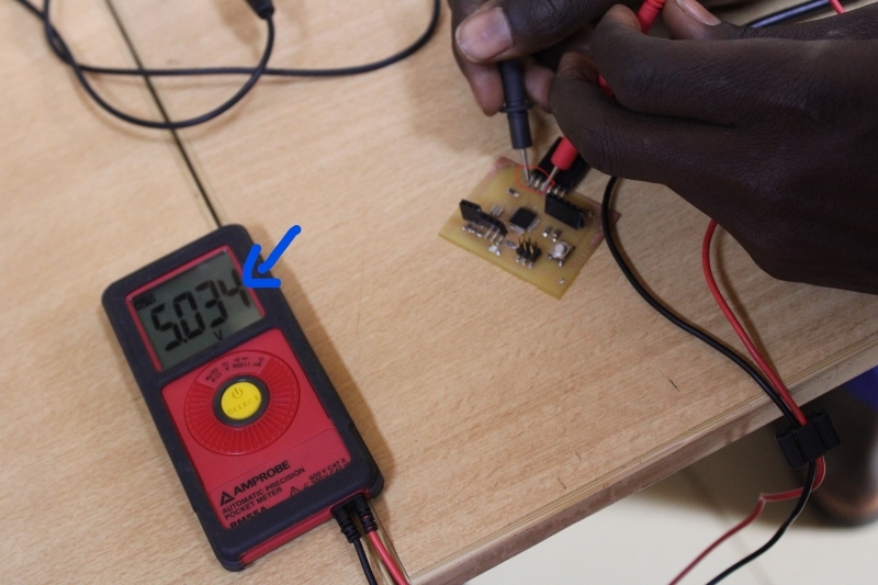
The multimeter is a device that allows the measurement of electrical quantities such as voltage, current and resistance. To be able to obtain the supply voltage of the circuit we used the multimeter of our FABLAB. Thus, as supply voltage we obtained 5.034V.
In our image below you can see the measurement between the VCC and GND and the arrow that indicates the result.
Voltage measurement with multimeter.
2. Oscilloscope
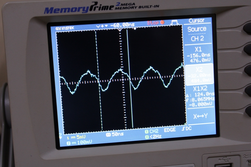
An oscilloscope is a measuring instrument intended to visualize an electrical signal, most often variable over time. To be able to obtain the frequency of the crystal (we will dwell on the Crystal in our individual projects) of the circuit we will use the oscilloscope of our LAB. For the test we used 100mV for the Volts/Div and 50ns for Time/Div. And as frequency the oscilloscope provided us with 7.984MHZ. At the time of the test we did not obtain a stable frequency.
This image shows us the frequency obtained on our oscilloscope.
3. LED circuit
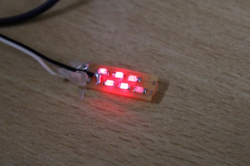
To improve our experience we decided to measure and vary the supply voltage of an LED circuit in order to observe the reaction of the LED.
During the work it was found that when the voltage increases the brightness of the LED increases. And at more than 3V the LEDs start to burn one by one.
The image above shows our test on the LED circuit
Individual Assignment
In the individual task I learned to design a PCB, to draw a hello-world echo map. At the beginning of the mission I had little difficulty with the design because it was my time to design a PCB. But with the help of my instructor, tutorials on You Tube and a colleague who knew a little about electronics I was able to get by.
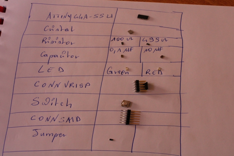
For this task we will use an ATtinny 44 microcontroller, an SMD push button, two SMD (Surface Mounted Device) LEDs of green and red color, an FTDI connector, an AVRISP SMD connector and a 20MHZ quartz crystal.
1. ATtinny 44 Microcontroller
A microcontroller is an integrated circuit that brings together the essential elements of a computer i.e. processor, memory (RAM and dead), a peripheral unit and input-output interface. Microcontrollers are characterized by their lower power consumption, a lower operating speed (a few megahertz up to more than one gigahertz) and a reduced blow to the microprocessor in computers.
We chose the ATtiny 44 because it's easy to use for beginners and it has less functionality less Input/Output pin.
2. Push button
A push button is a switching mechanism (interrupting electrical current or diverting it from one conductor to another) to control certain aspects of a machine or process.
3. LED
An LED or light-emitting diode is a device capable of emitting light when traversed by an electric current. It only lets the current pass in one direction.
4. Connectors
Connectors make it possible to establish a reliable connection between separate electrical or electronic systems. They are useful for both the transmission of energy and data.
5. Quartz crystal
An electronic quartz is an electronic component that has the useful property of oscillating at a stable frequency when electrically stimulated.
Photo
To realize my project, I used Eagle as software to make my PCB. I decided to use Eagle because it is easy to get and is easy to use for beginners. And I can also size my card as I wish. In addition with Eagle I had the opportunity to import the library of our FABLAB in order to be able to use the components we have.
6. Resistor
Resistance is the property that slows down the passage of electric current through any conductor, body or device. Here I used a resistor of 100 Ohms to protect the green LED and a resistance of 499 Ohms for the red LED. I noticed that when the resistance is high the brightness of the LED decreases and vice versa. I also used 0Ω resistors as a jumper.
The formula for finding the value of the resistance is as follows:
P = U*I and U = R*I
So we have:
R = U/I
7. Capacitor
A capacitor is an elementary electronic component consisting of two conductive reinforcements. Its primary function is to be able to store opposite electrical charges on its reinforcements. I used a 0.1 μF capacitor between Vcc and GND and a 10 μF capacitor with reset. The capacitor of 0.1 μF aims to stabilize the power supply of the circuit and that of the 100μF to prevent the microcontroller from reset when uploading the program.
The image represents all the components I used to design my PCB.
The image represents all the components I used to design my PCB.
List of components to use
| Designations |
Components |
Refernce |
| Microcontroller |
ATTINY 44A-SSU |
|
| Crystal quartz |
Resonator Ceramic |
20MHZ 15PF |
| Capacitor |
Ceramics |
10 μF 35V and 0.1 μF 250V |
| Resistor |
SMD |
100 Ω, 499 Ω and 10 kΩ. |
| Switch |
SPST Touch |
|
| LED |
RED, GREEN |
| Connector |
FTDI |
|
| Connector |
AVRISP SMD male |
2X3 |
| Connector |
Header SMD |
2X3 |
EAGLE
To realize my project, I used Eagle as software to make my PCB. I decided to use Eagle because it is easy to get and is easy to use for beginners. And I can also size my card as I wish. In addition with Eagle I had the opportunity to import the library of our FABLAB in order to be able to use the components we have.
Once started I went to the library of our FABLAB and select the desired components such as the 4ATtiny 44 and the LED.
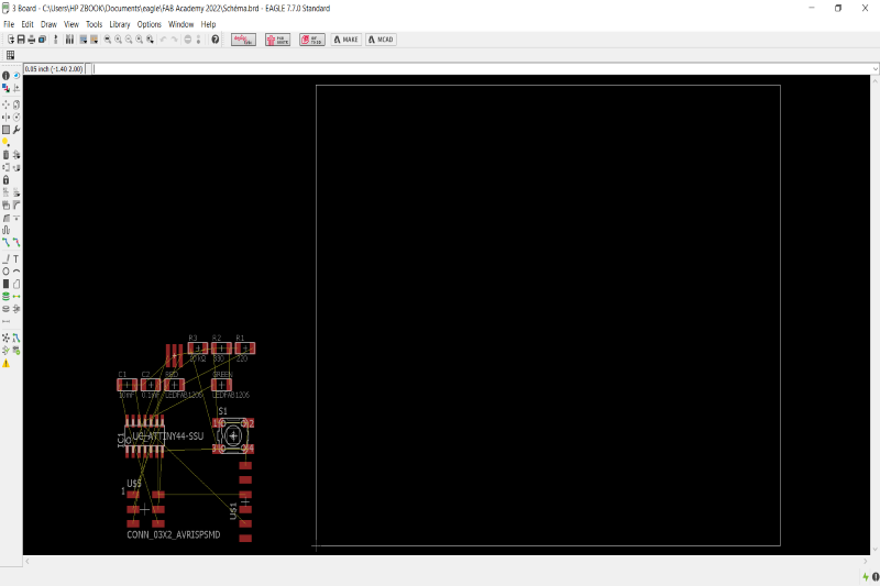
Schema
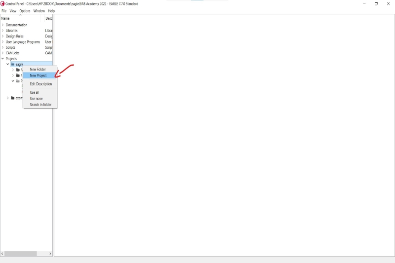
To start the circuit I started first by creating a new project. After creating the project I opened a new schema..
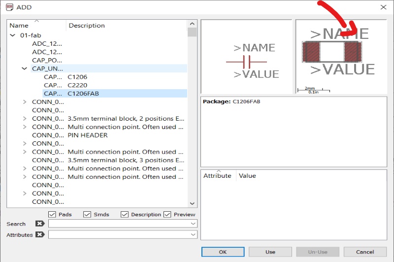
Once started I went to the library of our FABLAB and select the desired components such as the 4ATtiny 44 and the LED. The images below will help to better understand the process.
This image shows how I created a new project.
This image shows how I selected the circuit components.
Capacitor Selection(The arrow points to the capacitor)
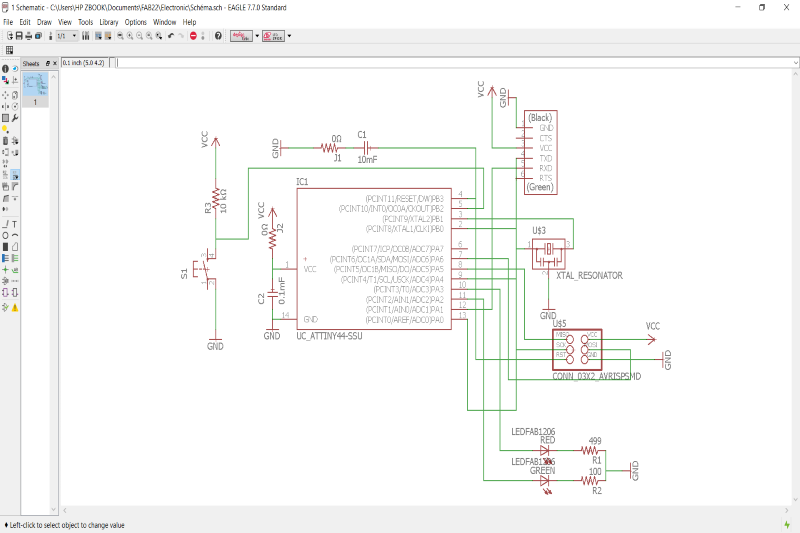
After selecting all the components, I started to wire them to have the final circuit of the project. The image above shows us how we did the wiring.
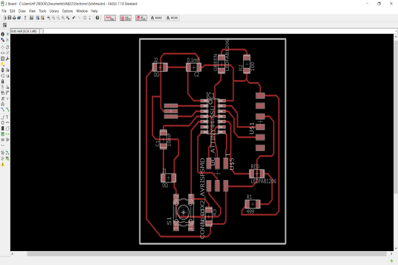
Path
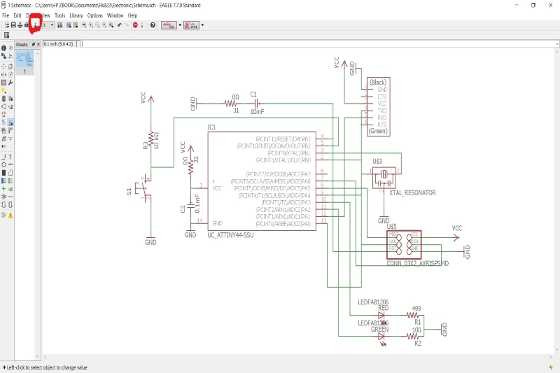
In this part I traced the path of the whole circuit. To do this I clicked on the circled icon and it send me on this window. I had to reposition all the components as I wanted, choose the thickness of my path to trace and the angle of my paths before starting to trace the path.
The images below show how I did it. Before ranking and after ranking.
Before classification of components)
After classification of components
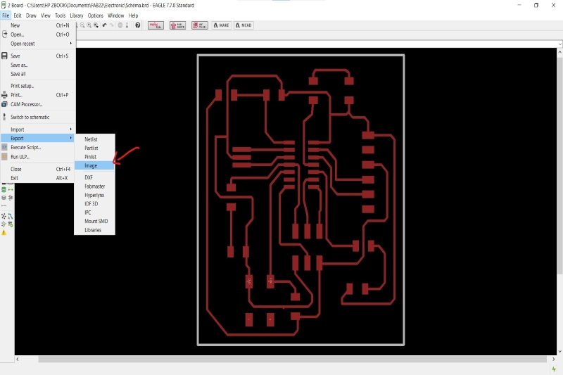
Once the circuit is finished I have to export it in image to be able to print it with the machine.
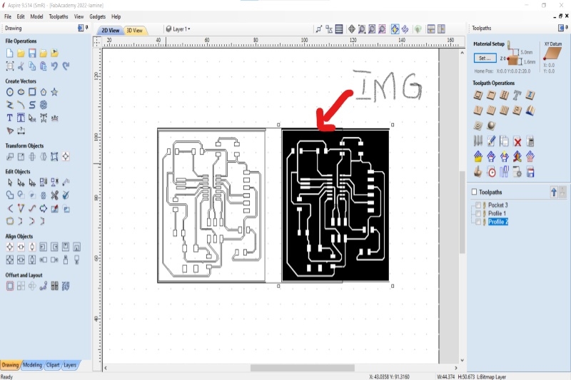
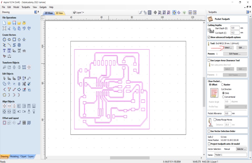
Aspire
Vectric Apire is a design software. In addition to the design it allows to control the machines as digital commonly called CNC. To control our machine I used Aspire to configure the machine.
Before I start I need to open Aspire and export the above image. Once the software was opened I created a new file. After creating the new file I opened the folder containing my image and performed a drag and drop to export the image to the software. After exporting the image I converted the image to plot to allow the machine to work better.
On the photo below, we have the arrow which is directed towards the exported image and on the other side the image converted into plotted.
The arrow points to the image file.
The arrow points to the exported image.
To be able to engrave and cut the circuit I used a copper plate. And it is on the plate that I will engrave my circuit. The plate is positioned manually on the (something costly).
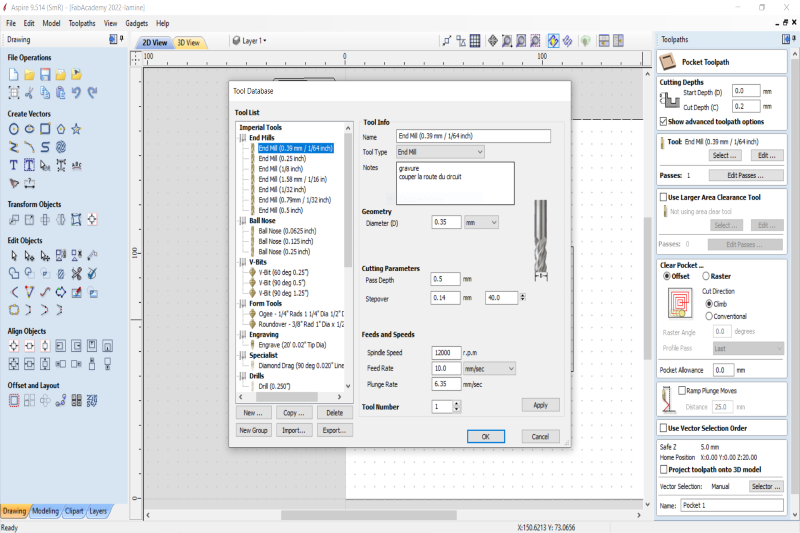
For the configuration, once the image export I had to position it on the plate but here it will not be manual but with the Aspire software. After positioning I chose the type of wick I want to use for engraving and then the type of wick I want to use for cutting my plate.
This image shows how to choose the wick and configure the machine for engraving and cut.
The image above shows us how to select the wick for the engraving.
I configured the machine according to the type of wick and the engraving.
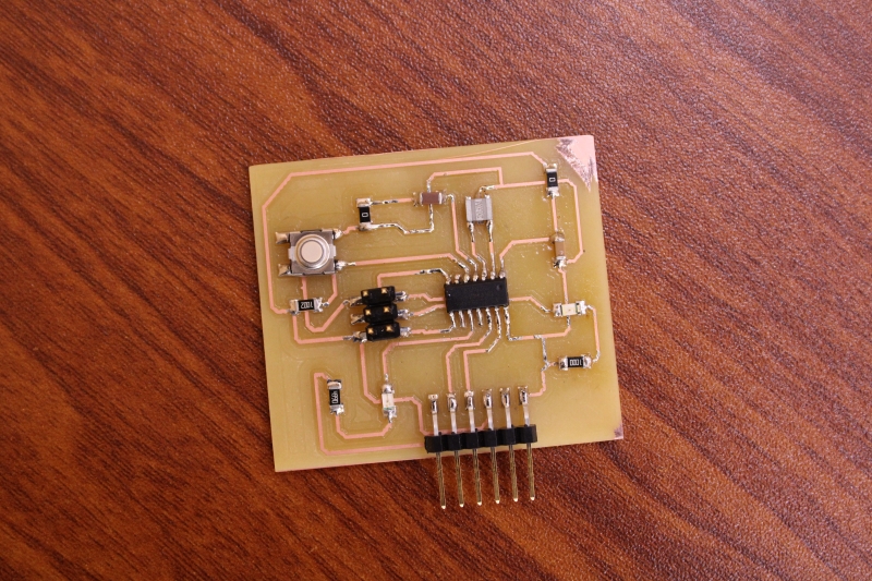
For pcb milling we will use Modela MDX 50. The procedure for using the machine is explained in the week of Electronic Production.
The image above shows the pcb.
Solder
In this part I will weld the different components on the pcb above. In this part I will weld the different components on the pcb above. We presented the welding tools during the Electronic Production week.
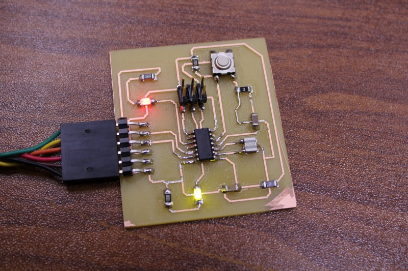
This image shows my final circuit after welding.
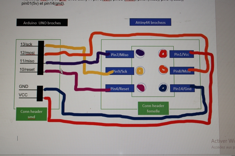
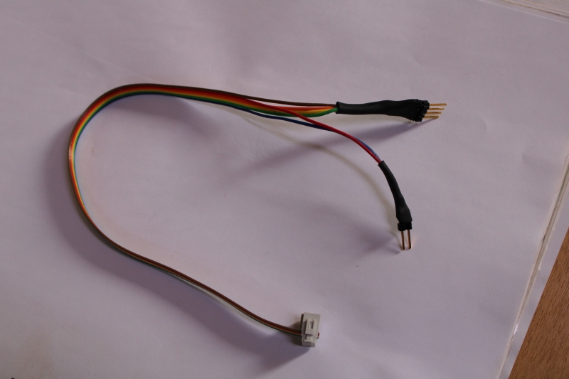
ISP cable
The ISP cable is a connector that allows the program to be transferred from the Arduino IDE to the microcontroller using the Arduino component as an ISP programmer. To design my ISP connector I used a female VRISP connector and a 2*3 connector and an FTDI cable or power supply. But my first try didn't work because I didn't understand the principle but after a second try I was able to get what I wanted.
To be able to find myself I did the following wiring beforehand. This setup shows us how to configure the ISP cable so that it can be used to transfer data from the Arduino to the microcontroller.
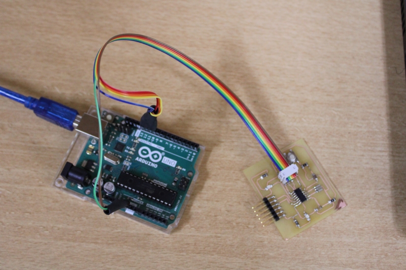
Connection to the arduino module
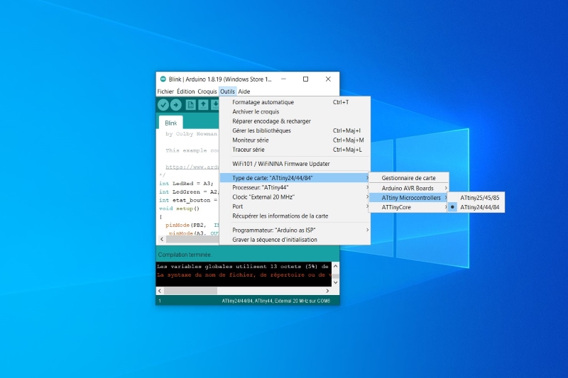
Arduino
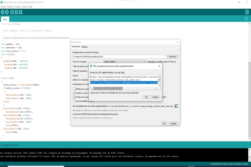
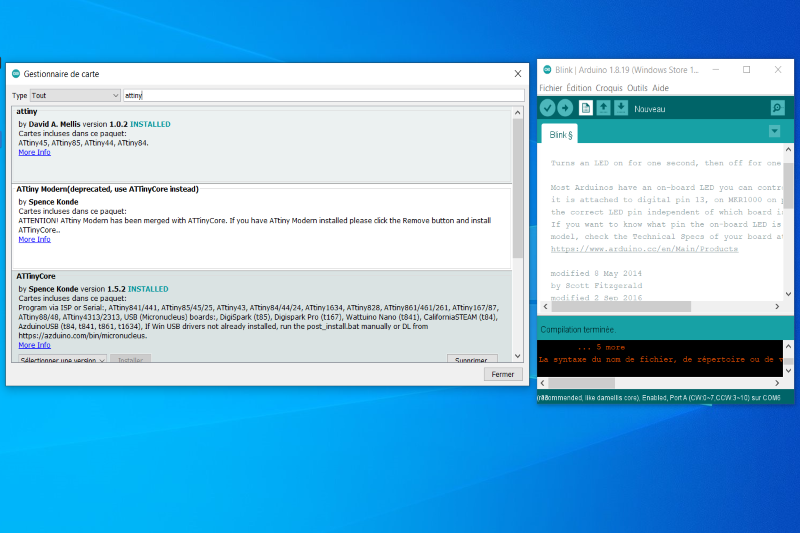
I used Arduino IDE to program my microcontroller. For this I configured Arduino IDE to behave like an ISP programmer in order to be able to upload my program to the microcontroller. As an Arduino module I used a UNO. To be able to configure I downloaded this reference "https://raw.githubusercontent.com/damellis/attiny/ide-1.6.x-boards-manager/package_damellis_attiny_index.json" so that I could download my Attiny on the Arduino IDE. The images below show how I set up my Arduino.
Downloading the Attiny to Arduino
Test
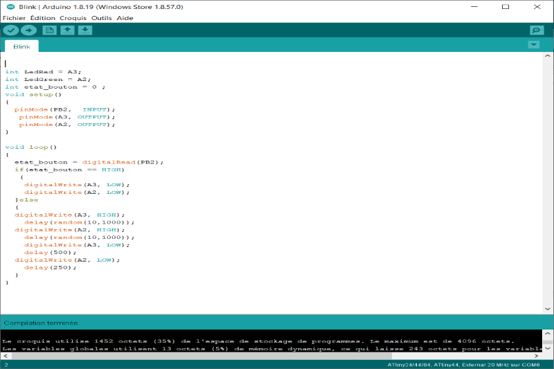
After the configuration I performed the test. During the test I noticed that the time put was not well respected. The response time lasts longer than I put in the code. So I decided to change my 8MHz Crystal to a 20MHz Crystal. After this change I noticed a small change. But the result was not very satisfactory.
My final circuit and final test