Output devices
In this part we have two assignments.
Group assignment:
- Measure the power consumption of an output edge device.
- Document our work.
Individual assignment: Add an output device to a microcontroller board you've designed and program it to do something.
Learning Outcome: Demonstrate the workflows used to control one or more output devices with an MCU card you designed.
Individual mission
During this week, I decided to design a board to control a servomotor. You're probably wondering why servo motors? To answer this question I will say that I need the servo motor in my final project so I thought why not achieve this at the same time. That's how the idea came to me.
The servo motor will control the opening and closing of the automatic bin. It will turn in one direction to open the trash can and in the other direction to close it. To be able to carry out this part I divided my work into several stages such as:
- The design of my circuit on Eagle;
- Manufacture, assembly and welding of the printed circuit board;
- Programming and testing of the circuit.
Circuit design
For the design of the circuit, I took a look in Neil's du FAB Class program to better understand that it is a first for me to design a board to control a servo motor.
So, I used Autodesk Eagle to design my circuit. The images below represent the different stages of design.
This image shows the wiring diagram of the circuit
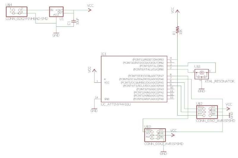
Wiring diagram
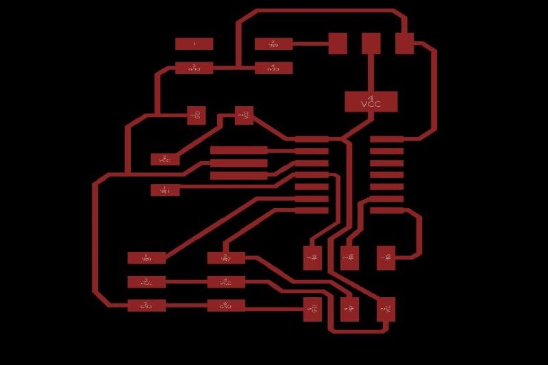
Board
Manufacture, assembly and welding of the printed circuit board
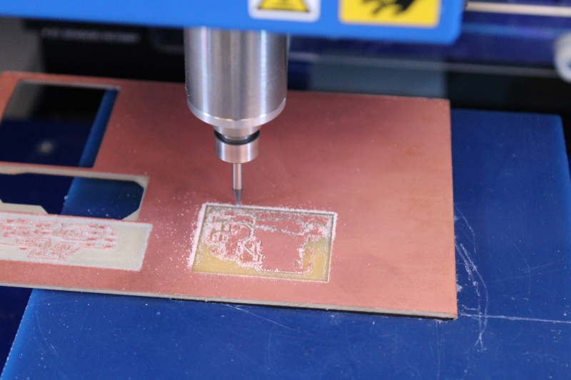
Manufacturing: For the manufacture I used Modela MDX 50 from our FAB LAB. To be able to burn to I used Vcarve Pro to configure the toolpath.
The image above shows the toolpath configuration
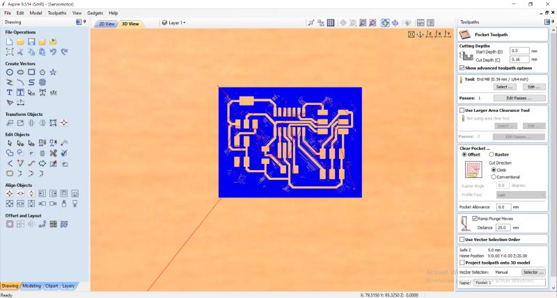
Engraving
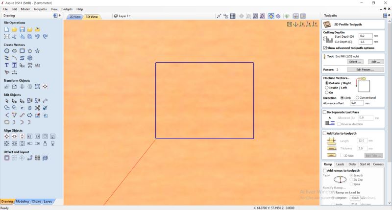
Cutting
After the board was made there was copper everywhere and the circuit was not smooth. So I used a cutter to make the plate smooth.
At the time of conception.
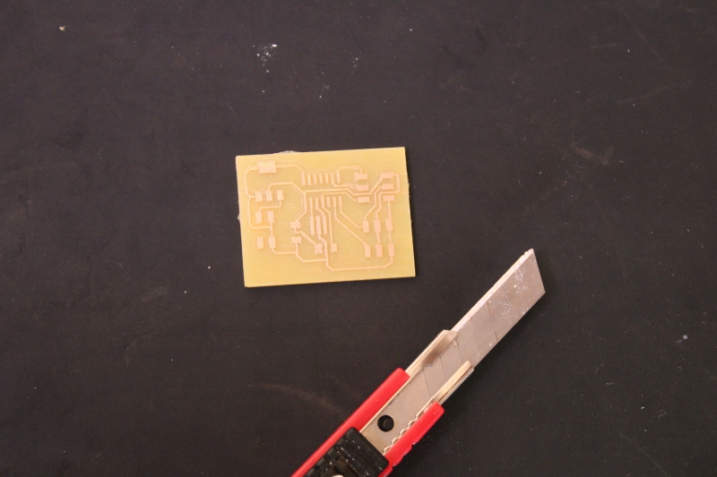
Circuit with copper fragments
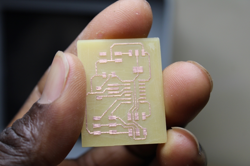
Circuit without copper fragments
Assembly: For the assembly we need some components like the ATtiny44A-SSU microcontroller, a resonator, a 5V 1A voltage regulator, a capacitor, a resistor, 2x3 connectors and a 2x2 connector (for an outdoor power supply).
The table below shows the different components.
List of components to use
| Designations | Components | Refernce |
|---|---|---|
| Microcontroller | ATTINY 44A-SSU | |
| Crystal quartz | Resonator Ceramic | 20MHZ 15PF |
| Capacitor | Ceramics | 10 μF 35V |
| Resistor | SMD | 10 kΩ. |
| Voltage Regulator | SMD | 5V 1A |
| Connector | Header SMD | 2X2 |
| Connector | Header SMD | 2X3 |
Welding: I used a soldering iron, a temperature conservation tab, the smoke vacuum cleaner, the board and the components.
The weld went well.
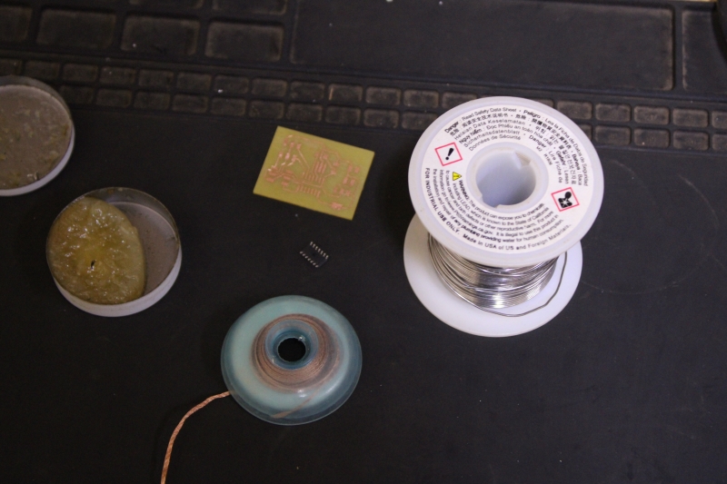
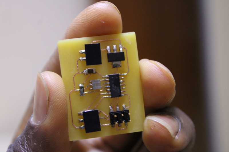
After welding
Programming and testing of the circuit
Programming: I used Arduino IDE to write my program. The goal is for the servo to rotate at an angle of 0 to 180° in one direction, wait a few moments and return to its original position.
The above program is program to control two servo motors.
#include avr/io.h
#include util/delay.h
#define output(directions,pin) (directions |= pin) // set port direction for output
#define set(port,pin) (port |= pin) // set port pin
#define clear(port,pin) (port &= (~pin)) // clear port pin
#define pin_test(pins,pin) (pins & pin) // test for port pin
#define bit_test(byte,bit) (byte & (1 << bit)) // test for bit set
#define position_delay() _delay_ms(1000)
#define PWM_port PORTA
#define PWM_direction DDRA
#define PWM_pin_0 (1 << PA6)
#define PWM_pin_1 (1 << PA7)
#define loop_count 30
int main(void) {
uint8_t i;
CLKPR = (1 << CLKPCE);
CLKPR = (0 << CLKPS3) | (0 << CLKPS2) | (0 << CLKPS1) | (0 << CLKPS0);
clear(PWM_port, PWM_pin_0);
output(PWM_direction, PWM_pin_0);
clear(PWM_port, PWM_pin_1);
output(PWM_direction, PWM_pin_1);
while (1) {
for (i = 0; i < loop_count; ++i) {
set(PWM_port,PWM_pin_0);
set(PWM_port,PWM_pin_1);
_delay_us(1000);
clear(PWM_port,PWM_pin_0);
clear(PWM_port,PWM_pin_1);
}
// 1.5 ms on time, both
for (i = 0; i < loop_count; ++i) {
set(PWM_port,PWM_pin_0);
set(PWM_port,PWM_pin_1);
_delay_us(1500);
clear(PWM_port,PWM_pin_0);
clear(PWM_port,PWM_pin_1);
_delay_us(18500);
}
// 2 ms on time, both
for (i = 0; i < loop_count; ++i) {
set(PWM_port,PWM_pin_0);
set(PWM_port,PWM_pin_1);
_delay_us(2000);
clear(PWM_port,PWM_pin_0);
clear(PWM_port,PWM_pin_1);
_delay_us(18000);
}
// 1 ms on time, channel 0
for (i = 0; i < loop_count; ++i) {
set(PWM_port,PWM_pin_0);
_delay_us(1000);
clear(PWM_port,PWM_pin_0);
_delay_us(19000);
}
// 1 ms on time, channel 1
for (i = 0; i < loop_count; ++i) {
set(PWM_port,PWM_pin_1);
_delay_us(1000);
clear(PWM_port,PWM_pin_1);
_delay_us(19000);
}
// 1.5 ms on time, channel 0
for (i = 0; i < loop_count; ++i) {
set(PWM_port,PWM_pin_0);
_delay_us(1500);clear(PWM_port,PWM_pin_0);_delay_us(18500);
clear(PWM_port,PWM_pin_0);
_delay_us(18500);
}
// 1.5 ms on time, channel 1
for (i = 0; i < loop_count; ++i) {
set(PWM_port,PWM_pin_1);
_delay_us(1500);
clear(PWM_port,PWM_pin_1);
_delay_us(18500);
}
// 2 ms on time, channel 0
for (i = 0; i < loop_count; ++i) {
set(PWM_port,PWM_pin_0);
_delay_us(2000);
clear(PWM_port,PWM_pin_0);
_delay_us(18000);
}
// 2 ms on time, channel 1
for (i = 0; i < loop_count; ++i) {
set(PWM_port,PWM_pin_1);
_delay_us(2000);
clear(PWM_port,PWM_pin_1);
_delay_us(18000);
}
}
}
Test: In this part I used my UBSTiny to program the servo motor. So, I connected my servo motor to my PCB card, the PCB to USBTiny and the USBTiny to my computer.
I also used an external 9V power supply to power my ATtiny 44. The image above represents the connection.
