In this we will be interested in embedded programming is learning how to program a microcontroller. This week's mission is to compare performance and development workflows for other architectures, read our microcontroller's datasheet, and use a program to program our board to do something. For this mission we will focus on the ATtiny more specifically the 44A-SSU.
Data sheet
The technical sheet is a sheet containing all the technical information relating to a material from a supplier. It makes it possible to understand the functioning of the material and its different components that constitute it. In our case it is the technical sheet of an Attiny 44A microcontroller. To have the technical sheet of our microcontroller we go to the Atmel website and download the document. After reading we noticed that the document contains the main characteristics of the microcontroller, the pinout scheme, the architecture overview, the register summary, the assembly instruction set, the packaging information and above all describes in detail the functionalities of the microcontroller.
1. Microcontroller feature
According to the technical sheet we three (03) series or version namely ATtiny24A, ATtiny44A, ATtiny84A. They have the same architecture and feature set, but different amounts of flash memory. They have two PWM channels and they can be used to turn analog signals into digital signals.
They also list edges, such as timers/counters, ADCs, analog comparators, and serial interfaces. ICs are available in different packages, ranging from 14-pin SOIC or PDIP to 20-pin VQFN.
There are 12 programmable I/O lines on the MCU and it can operate with supply voltages from 1.8 to 5.5V, with operation at higher frequencies requiring higher supply voltages. Roughly speaking, this makes it possible to optimize energy consumption in relation to processing speed.
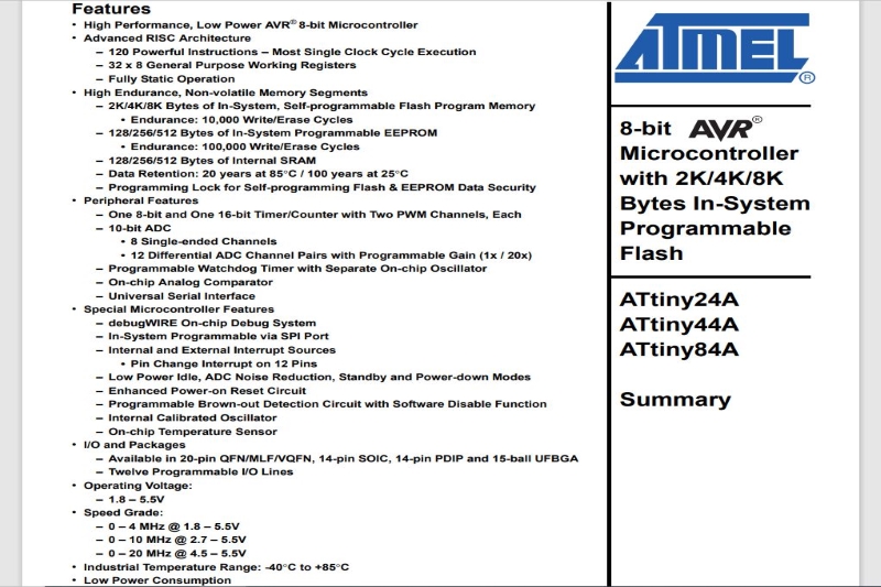
The image below is a capture of the card. It details the different functionalities of our microcontroller.
Features of ATtiny44.
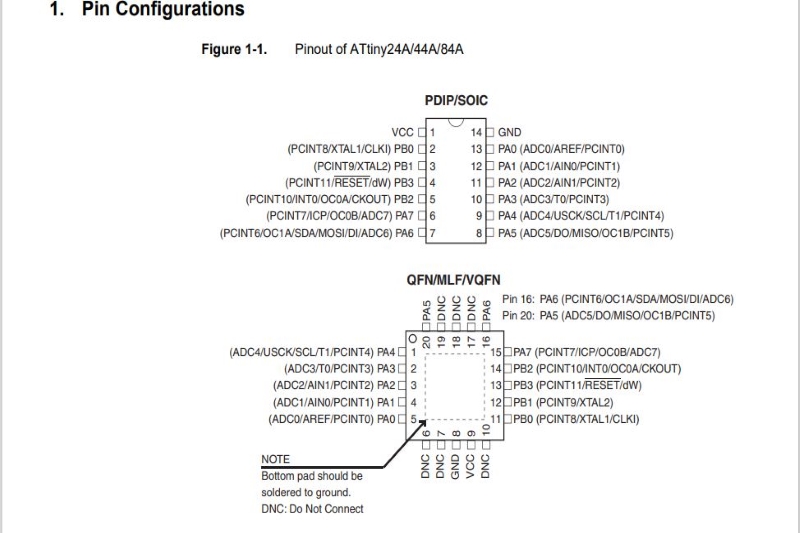
2. Pinout scheme
The most useful is the pinout of the MCU. Depending on the packaging, this helps to design a PCB. It is very important to note that all pins have multiple characteristics, so depending on the project, one can choose the pins to use for particular tasks.
The default pins are Vdc (supply voltage) and GND (ground). Port B (PB0: PB3) is a 4-bit bidirectional I/O port with internal pull-up resistors. PB3 has RESET capability. However port A is an 8-bit bidirectional I/O port with internal pull-up resistors. It has alternative functions like analog inputs for ADC, analog comparator, timer/counter, SPI and pin change interrupt.
The image below represents the different pins.
Pin configurations
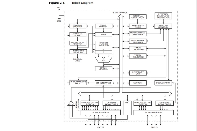
3. Architecture Overview
The architecture overview shows us that the AVR kernel combines a rich instruction set with 32 general-purpose working registers. All 32 registers are directly connected to the arithmetic logical unit (ALU), allowing two registers accessible in a single instruction executed in a clock cycle.
The image above represents the architecture overview
Architecture Overview
3. PROGRAMMING
In this part of my work, I used several languages to program my map. Among these languages, we have avr-gcc and c.
1. Programming with Arduino IDE.
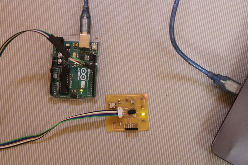
For this task, I used my hello card that I created during the electronic design week with an LED and a push button. To program it I also used the ISP cable that I created during the electronic design week. To start I connected the hello board to the ISP cable and connected the ISP cable to the Arduino Uno module.
The image above represents the configuration
Arduino as a programmer
I started the training late so I did not have the opportunity to realize a programmer in week 5 electronic production. So for this week I used the Arduino module as a programmer. In week 7 I explained how to configure the Arduino module as a programmer. But before I started coding in Arduino IDE, I clicked on Tools to check the type of board and the programmer chosen.
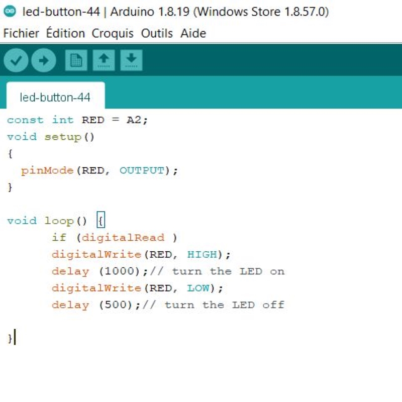
I started with a code that flashes an LED. The image below shows the flashing program of an LED.
Flashing coder
This video shows the flashing of LEDs
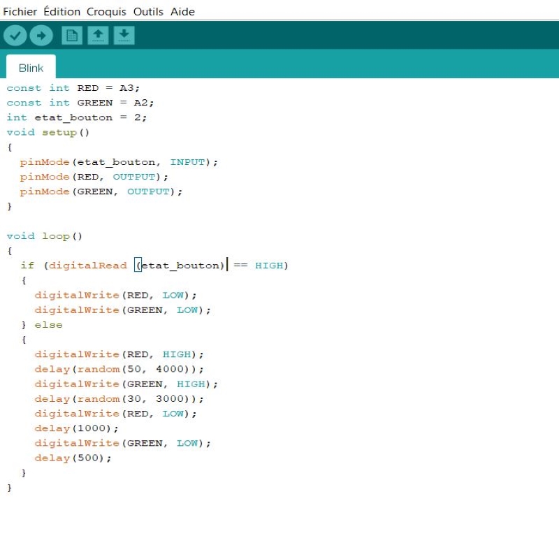
Here I coded taking into account the push button. The action on the push button turns off the LEDs. The image below shows the Swhitch program .
Action on the push button
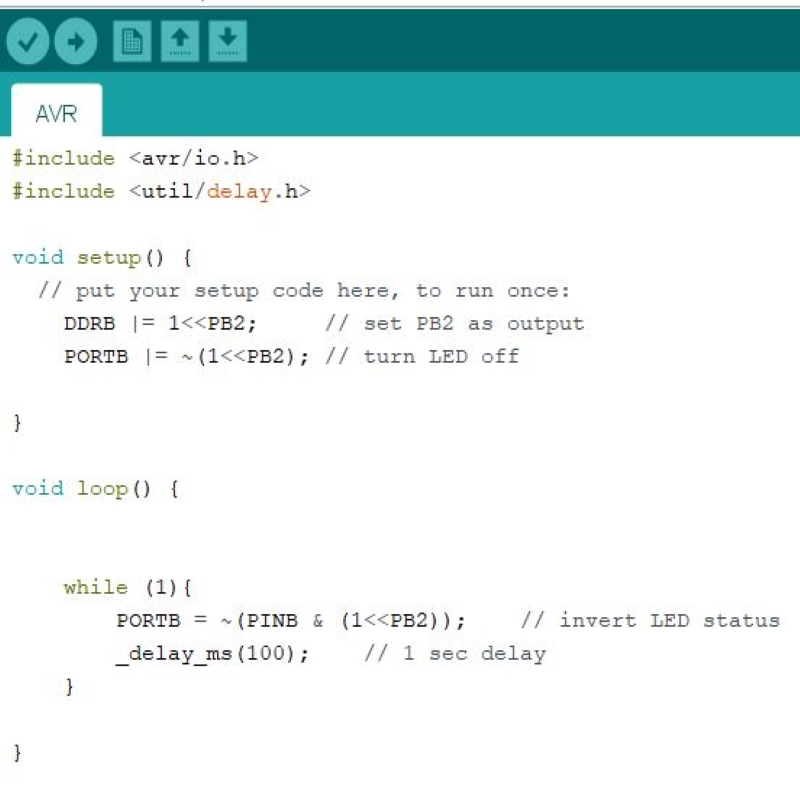
2. Programming with avr-gcc
I started with Atmel Studio. I went to the site and downloaded the Atmel Studio software. However I could not use it because I did not have the Atmel module to use as a programmer. So, I used Arduino IDE with the same configuration as week 7 i.e., hello board, Arduino Uno module and ISP cable.
To be able to code with Arduino in avr-gcc I have included the library avr and delay.