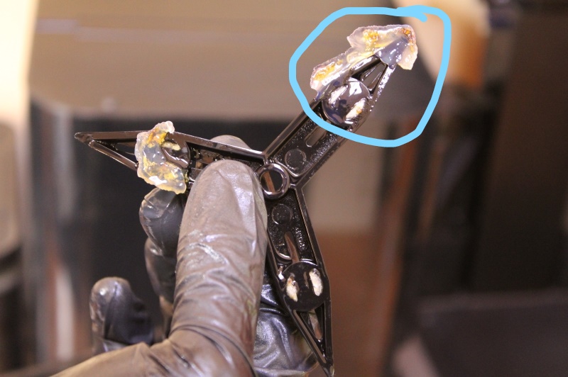
On our image we see that the angle is no longer accurate to 100 degre.
Angle test (Inaccurate angle at 100 degree)
3. Precision
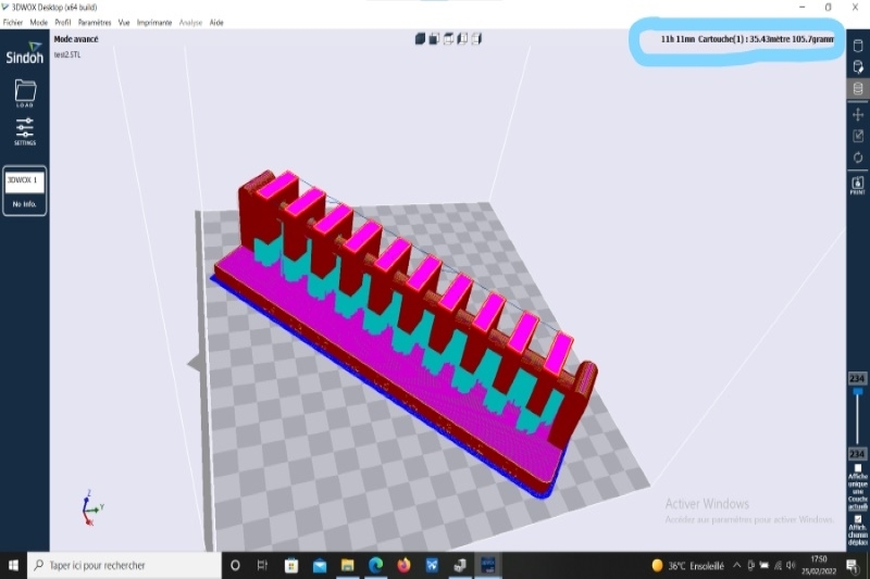
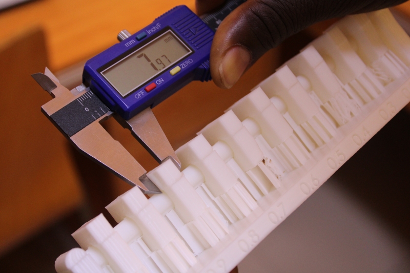
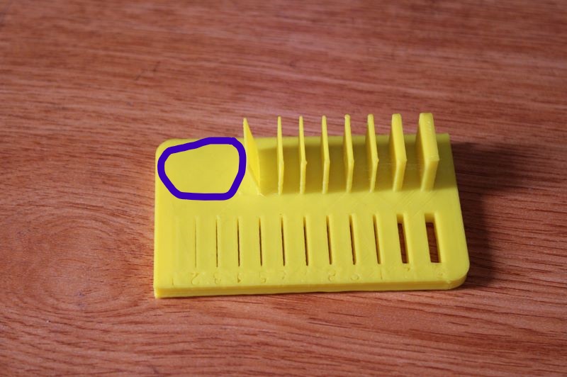
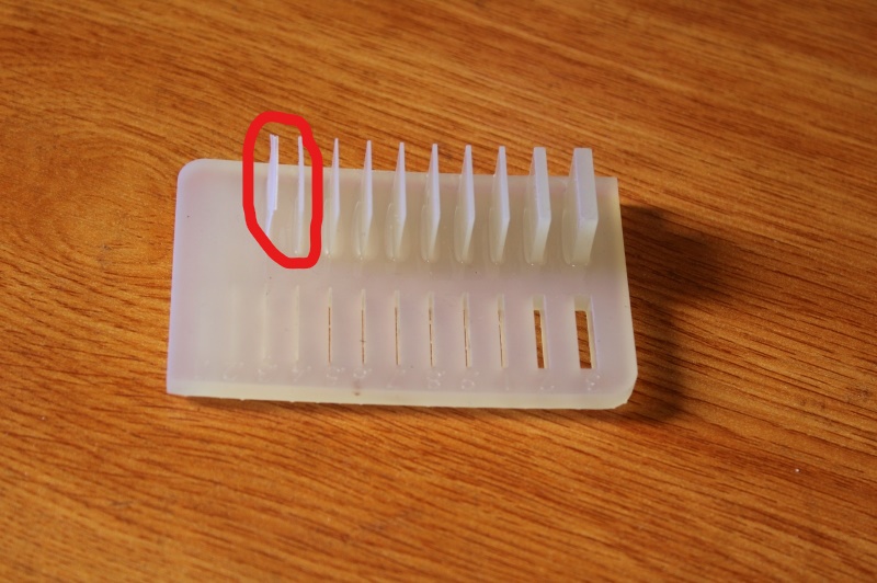
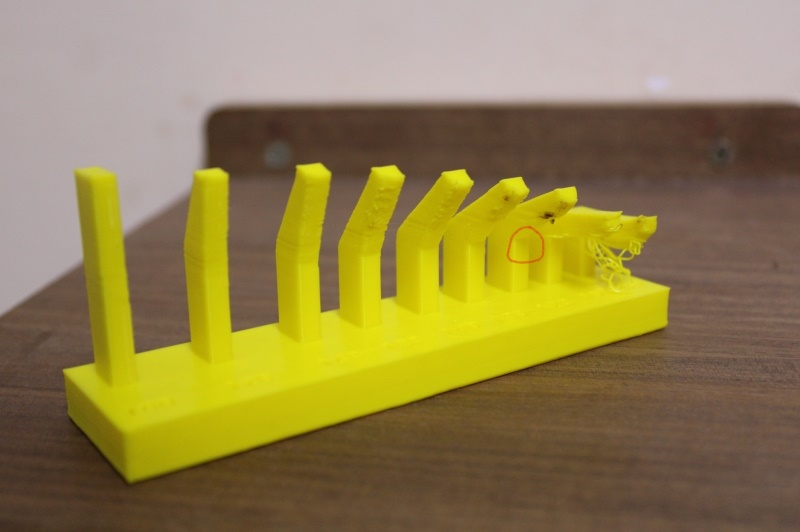
For this task we wanted to test the precision and printing tolerance of our printer.Thus, we carried out several tests with different measurements. We started with a 0.2mm print as the layer writer. After printing, it was found that prints smaller than 0.5mm were not printed and holes were visible from 0.2mm. Nevertheless, the results were accurate from 0.8 mm.
The circled part on our image represents the space of unprinted objects. These objects have a thickness between 0.1 and 0.5mm.
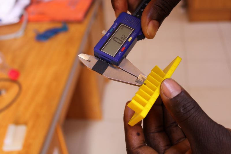
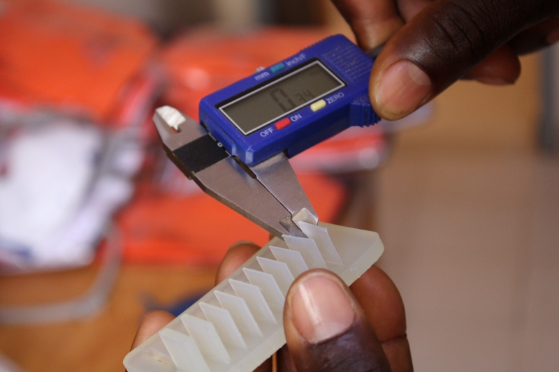
Accurate measurement to 0.82mm
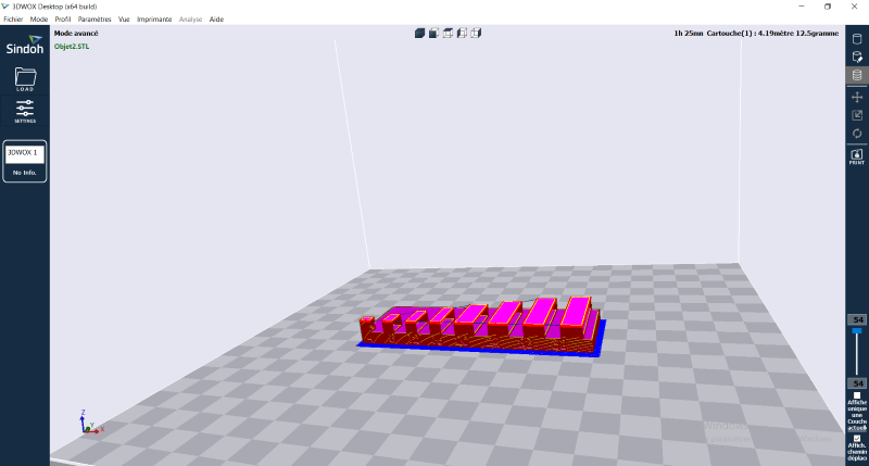
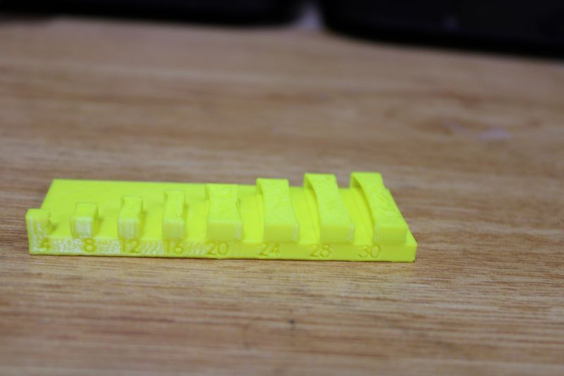
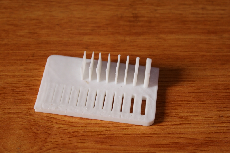
We continued with 0.4mm and 0.05mm tests.But we did not get the expected results because there are no big differences with the previous results. However, we noticed a slight difference with the 0.05mm print as the print was a bit more accurate from 0.6mm.
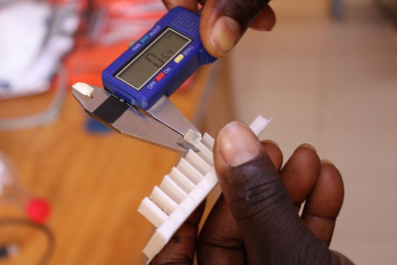
Accurate measurement to 0.64mm
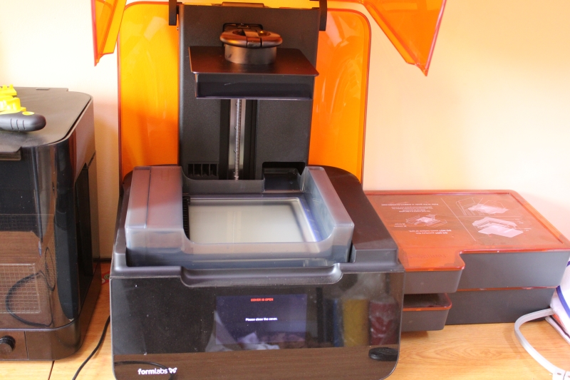
Formlabs 3
In this part of our work, we will continue the tests with our second printer, namely formlabs3.
The Form 3 is an industrial resin 3D printer and it uses Prefrom as a slicer.
Characteristics
Maximum precision: 25 microns (0.025 mm/layer).
Dimensions of the printing layer: 145x145x185mm.
Compatible materials Formlabs Resins.
LFS (Low Force Stereolithography) technology.
Advanced Z resolution: 25 to 300 micron.
Advanced 25 micron XY resolution.
Laser spot size 82 microns.
Software: Pre-form version.
Files supported: .stl, .obj.
Spécifications Laser: Class 1 Laser Product.
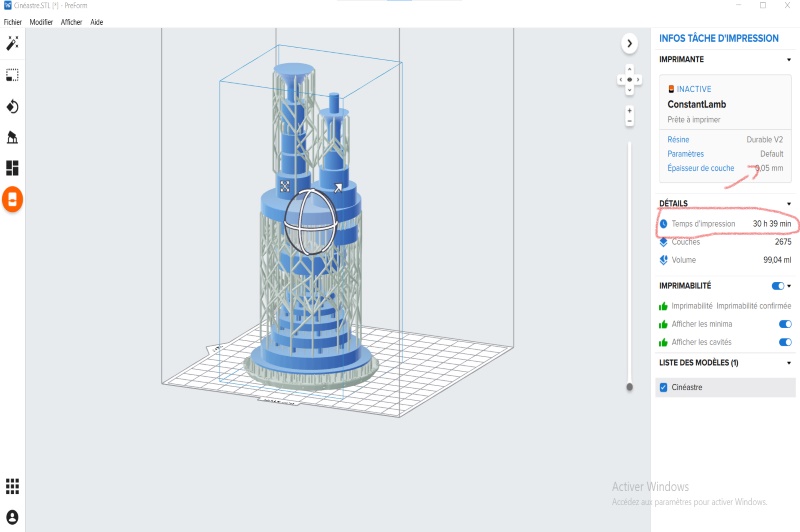
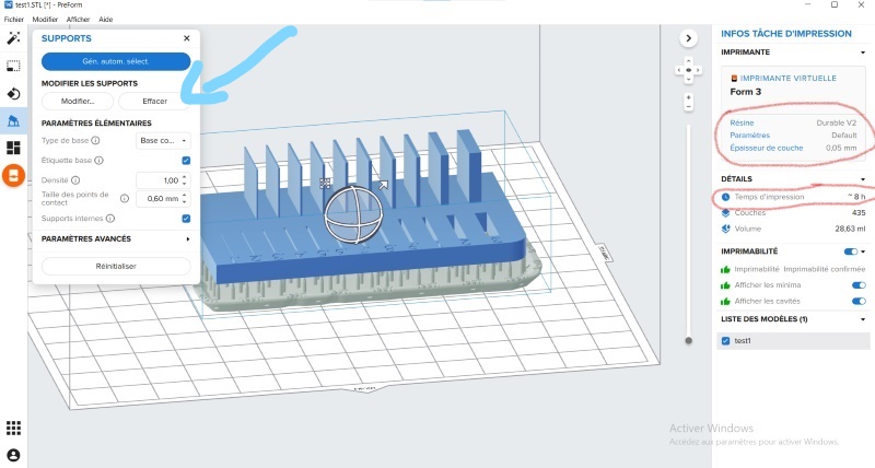
For the test, we used a layer thickness of 0.05 mm with a time of 8h.
This image represents our configuration on Preform. We have the printing time, the type of material used circled in red and the blue arrow to indicate the automatic generation of the support.
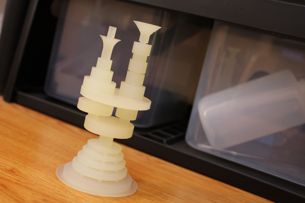
Once the object was printed, we noticed that even 0.3mm objects were visible and the object was smooth.In addition to being smooth, the measurements were very precise.However below 0.3mm the cuts were not very visible.
In this image we could see the missing objects on our previous tests.
Accurate measurement to 0.34mm
This represents our impression with more accurate measurements.
Comparison
During our work we noticed some difference between the printers. Its differences are among other things the performance and the print quality of each printer.We will therefore illustrate this in the table below.
| Printing time |
Print quality |
Settings |
| Both printers have a great print time. When we take an object with the same size and layer height like 0.05mm, we can see that the print time difference is about 10 hours or even more. Formlabs takes much longer than the Sindoh 3DWOX1. |
Regarding the quality of printing formlabs is more precise in measurements and smoother. |
Regarding the layer height on 3DWOX1 we can choose the thickness according to our needs while the parameters on formlabs are prefinished and we can only use 0.05mm. |
Individual assignments
In this part of our work, I used different printers with different settings to be able to obtain the desired result. But as we said at the beginning of our work, to model the objects we have two methods. The process of additive manufacturing which produces objects by adding material layer by layer (the process used by 3D printers) and subtractive manufacturing which removes material from a solid form to create parts (this process is used by CNC machines).
We will always use printers because it would be difficult to use subtractive manufacturing to be able to obtain our object. We will still be using printers as it would be difficult to use subtractive manufacturing to be able to get our design, since our design has hidden corners and the objects are also overlapped.
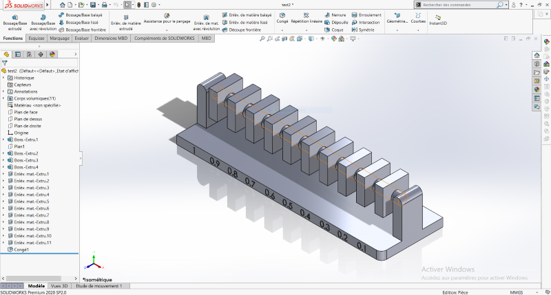
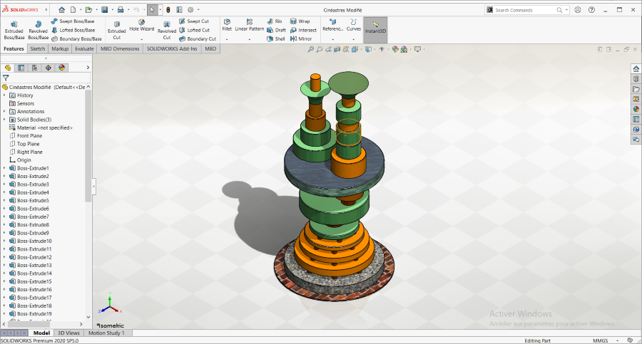
To start I used solidworks to draw the model of the desired object.
The object is a roundabout in the city of Ouagadougou. I wanted to draw it because Ouagadougou being the capital of African cinema, it represents the cinematographic culture not only of Burkina Faso but also of all of Africa.
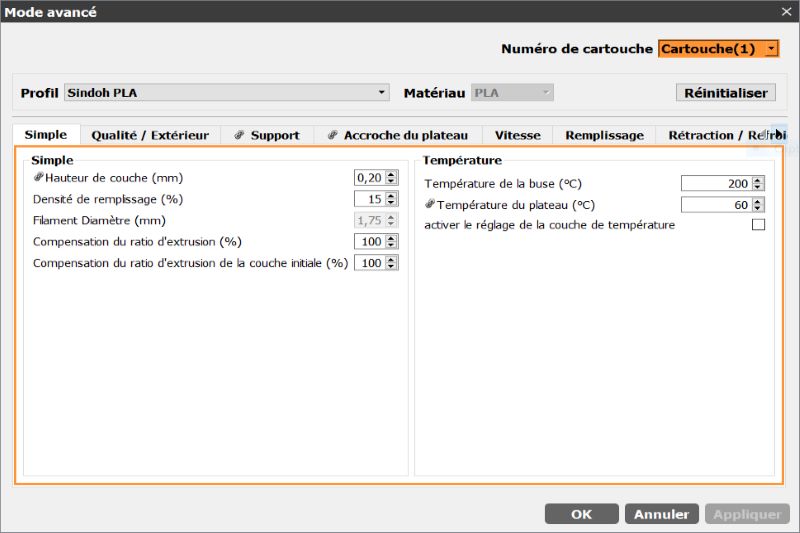
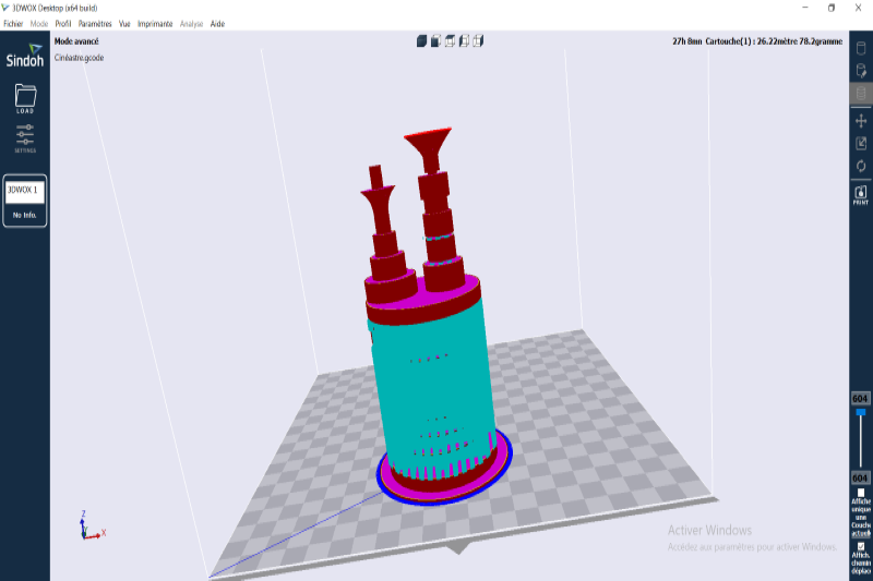
3DWOX1 settings with 0.05mm slice
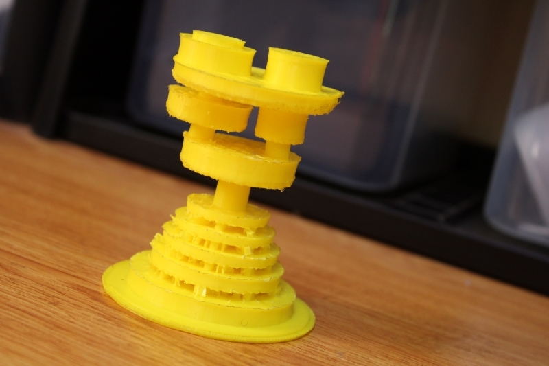
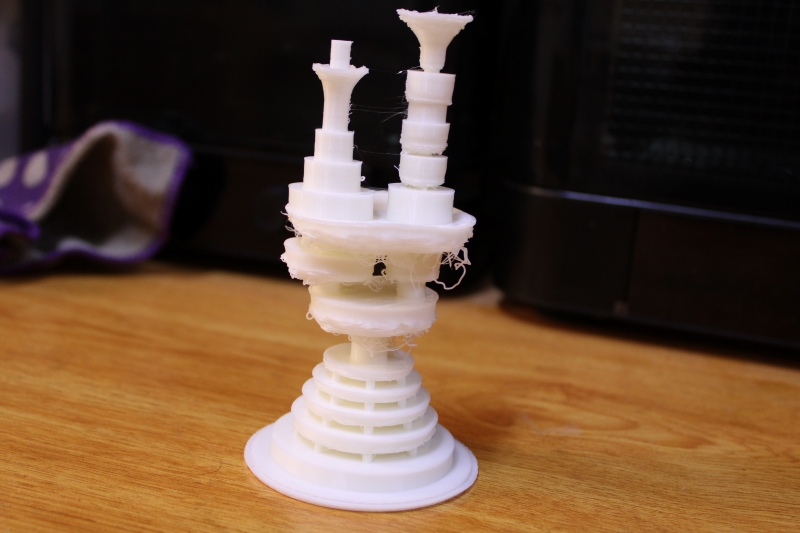
Printed object with support
After this disappointment I therefore decided to make another impression but this time I played on the printing layer and the removal of the support.This allowed me to reduce the printing time but the result turned out to be worse than the first experience.
Printed object without support
In reality I did not obtain satisfactory results with Sindoh 3DWOX1.So I decided to continue the adventure with formlabs for see.
For thhis I used support and 0.05mm as print layer.
With formlabs, I got what I wanted and above all the precision of the measurements was satisfactory.
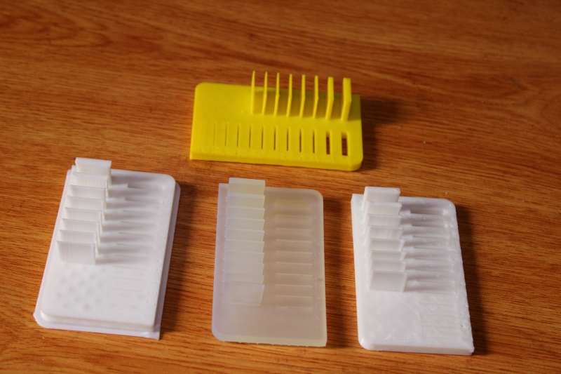
Final 3D object
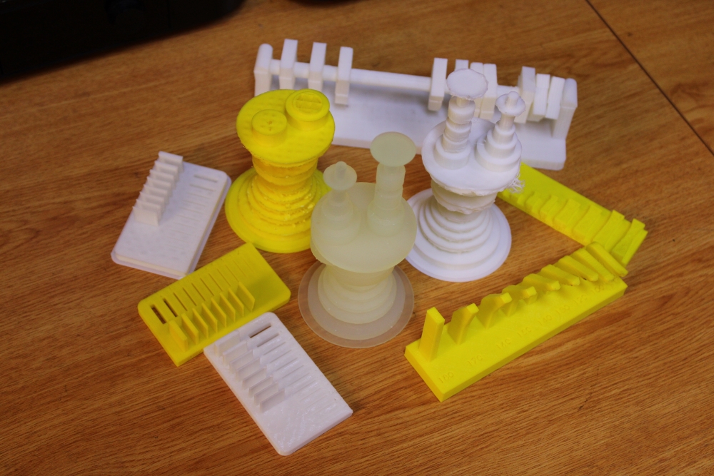
All printed objects
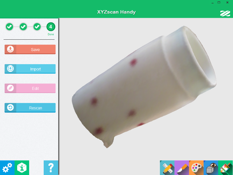
3D Scanning
In this part of our work, we use a scanner to digitize an object and obtain it in 3D. As this is my first time using a 3D scanner, I was really looking forward to using it.
As 3D scanner in our FABLAB, we have XYZprinting product.
Before starting the scan, we installed the software that will send us the image of the scanned object. As software, we used XYZscan Handy which is the software supplied with the scanner.
With our scanner, it was not only difficult to scan a small object but it also did not take black colors into account.
To remedy this problem we used a white powder on the object to make it more white. Additionally, we've dropped a black cover underneath to let the object show through.
Encountered difficulties
During the work, we encountered several difficulties.
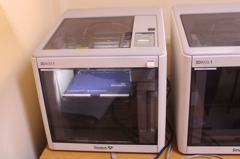
We had one out of three Sindoh printers working normally.Given the printing times of the printers, we could not work with a single printer.So we decided to restore both printers to good condition.
After diagnosis, we found two problems on Sindoh printers, namely:
nozzle clogging;
and filament intersection clogging.
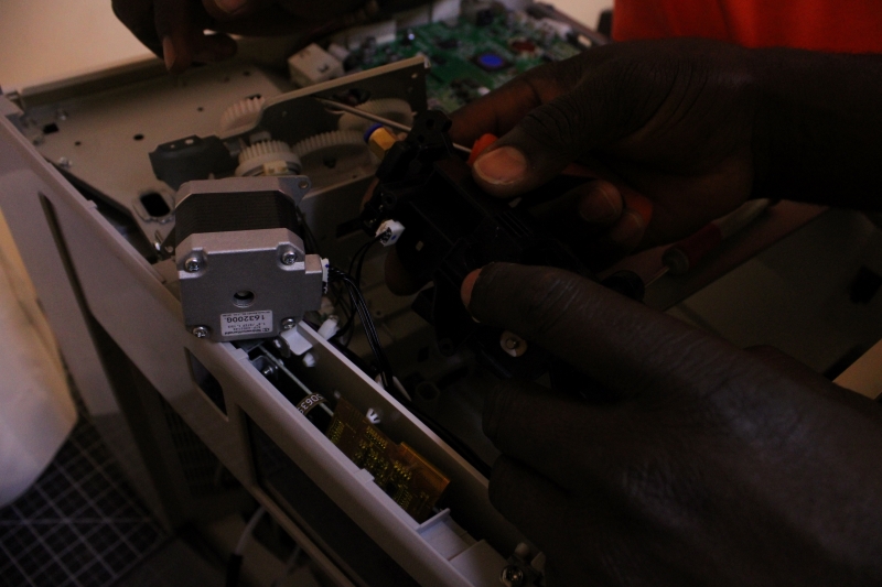
1. Nozzle repair
For the repair, we proceeded to disassemble the nozzle to be able to remove the clogged filament. This operation allowed us to recover a printer.
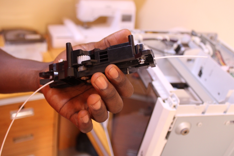
2. Filament intersection point input
Once the printer was running we noticed that the motor turns for a moment and after a while we hear the noise of the gears and the filament does not come out And the machine pops out this error."Remove the cartridge. Check if there is any filament left in the tube or at the entrance to the filament insertion point"
So we thought that for the error the intersection point of the filament was clogged. And for noise, the gears weren't well meshed or they lacked lubrication.After dismantling we noticed that the sprockets were not well meshed and we greased the pins a little. However, the entrance to the point of intersection of the filaments was not blocked.
Faulty part (the entrance to the point of intersection of the filaments)
Once reassembled the error continued to appear but we no longer heard the noise of the gears.So we started testing with the two imprimantes Sindoh.
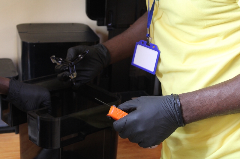
3. Cleaning machin
It is a machine that cleans objects printed with formlabs.She uses alcohol for cleaning.During our test, we found that all the alcohol had evaporated and the resin remained stuck inside. We had to do the complete cleaning of the machine with alcohol in order to use it.
On our image above, the circled part represents the resin stuck inside the machine