14. Embedded Networking and communications
This week Hero shot!
This week Checklist
Group assignment
- [✓] Send a message between two projects
- [✓] Document our work
Individual assignment
- [✓] Design, build, and connect wired or wireless node(s) with network or bus addresses
Group assignment
This week, our group try to do send a message between two projects. Please click here to see more details of our group assignment.
Individual assignment
This week I worked on connect two SAMDuino board thought serial communication, When I twist the servo of the input board, the servo of the output board will also rotate to the same position.
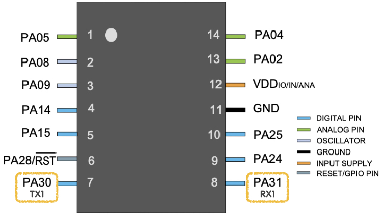
▼ SAMD11 PA30 and PA31 pin are serial1 port.
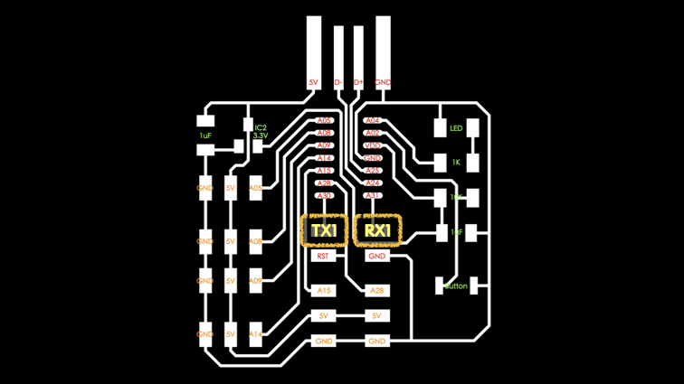
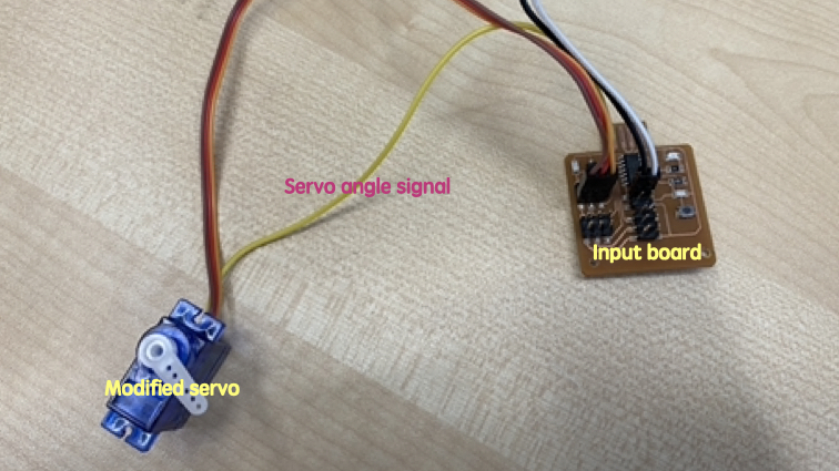
▼ I am using input week PCB to do this week assignment.
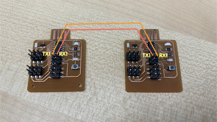
▼ Use two cable to connect input board TX1 to output board RX1 and input board RX1 to output board TX1.
▼ I modified the servo, solder additional cable to potentiometer in servo, it can help me to read servo angle.
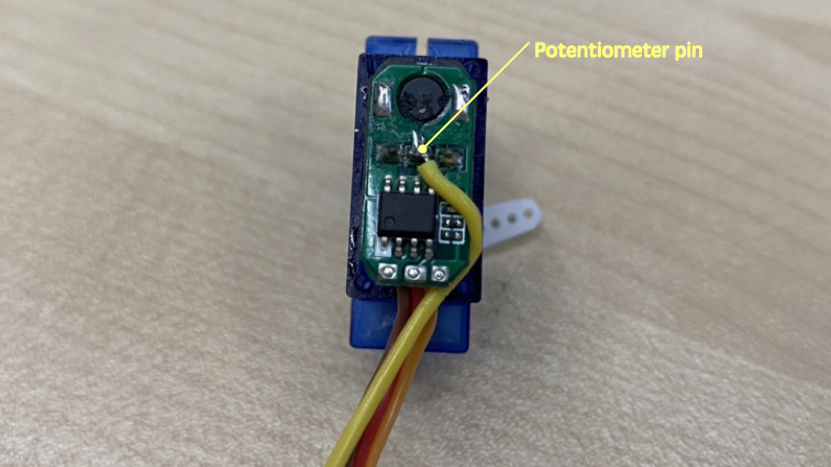
▼ So, you can see 4 pins connected to servo on input board.
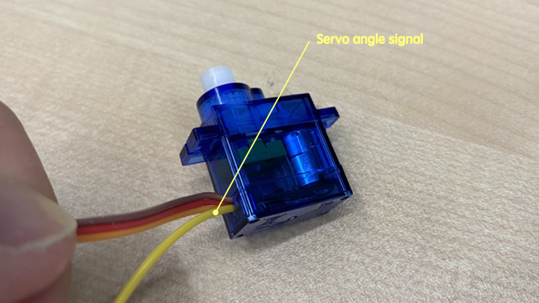
▼ I connected modified servo to input board and write program to read servo angle.
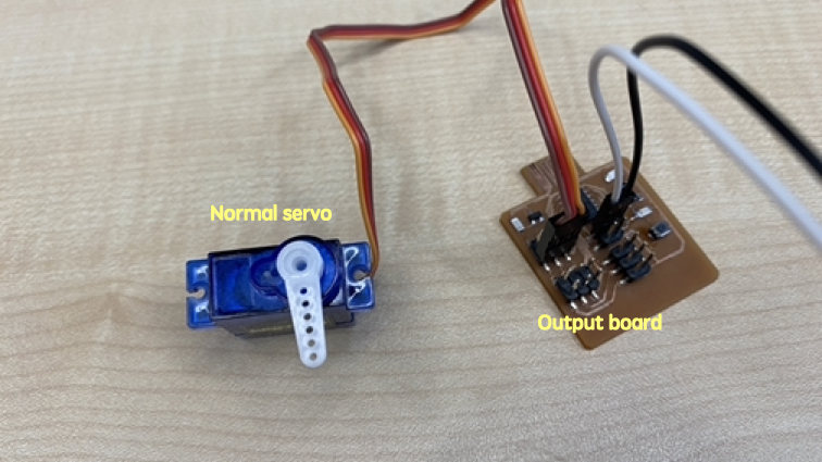
▼ And connect a normal servo to output board.
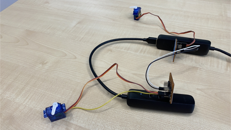
▼ Here is how the connect whole circuit.
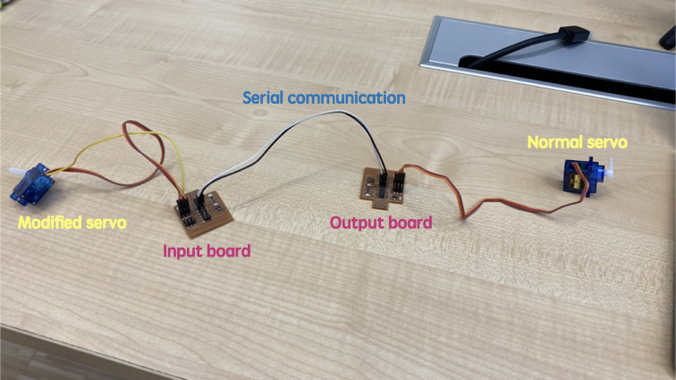
▼ Final setup just like there, User rotate the input servo, input board read the input servo angle and send out thought serial communication, output board get message from serial communication, then change to angle and generate PWM to mark output servo rotate to angle same at input servo.
Coding
▼ program for input board
int inputPin = 5; // Input sensor pin number

void setup() {
  pinMode(inputPin, INPUT); // Set pin mode (INPUT / OUTPUT)

  Serial.begin(9600); // sets the data rate in bits per second (baud) for serial data tranmission
  Serial1.begin(9600); // sets the data rate in bits per second (baud) for serial1 data tranmission (SAMD11C PA30-TX1 PA31-RX1)
}

void loop() {
  int inputValue = analogRead(inputPin); // read inputPin analog signal (0-1023)

  Serial.println(inputValue); // output to serial monitor or plotter
  Serial1.println(inputValue); // output to serial1 monitor or plotter

  delay(100); // delay 0.1 second
}
▼ program for output board
int servoPin = 8; // Servo pin number
int angle;
String readString;

void setup() {
  pinMode(servoPin, OUTPUT); // Set pin mode (INPUT / OUTPUT)

  Serial.begin(9600); // sets the data rate in bits per second (baud) for serial data tranmission
  Serial1.begin(9600); // sets the data rate in bits per second (baud) for serial1 data tranmission (SAMD11C PA30-TX1 PA31-RX1)
}

void loop() {
  while (Serial1.available()) {
    delay(2);  //delay to allow byte to arrive in input buffer
    char c = Serial1.read();
    readString += c;
  }

  if (readString.length() >0) {
    Serial.println(readString);

    angle = map(readString.toInt(), 0, 1023, 0, 180); // map(value, fromLow, fromHigh, toLow, toHigh)
    servoPulse(servoPin, angle);
    readString="";
  }

  delay(50);
}

void servoPulse (int servo, int angle) {
  int pwm = (angle*11) + 500; // Convert angle to microseconds
  digitalWrite(servo, HIGH);
  delayMicroseconds(pwm);
  digitalWrite(servo, LOW);
}
Downloads
Arduino program for two board
input_board.ino
output_board.ino