7. Electronics design
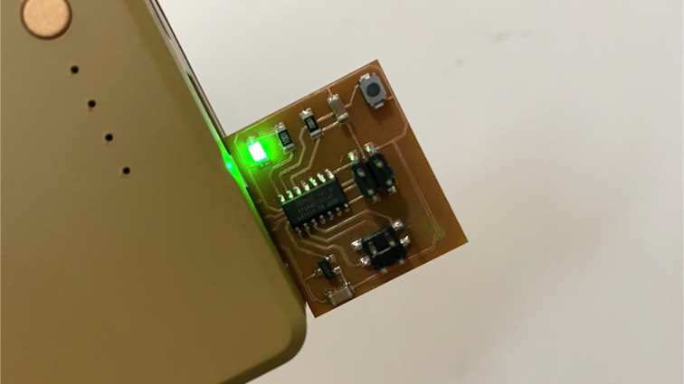
This week Hero shot!
This week Checklist
Group assignment
- [✓] Use the test equipment in our lab to observe the operation of a microcontroller circuit board (in minimum, check operating voltage on the board with multimeter or voltmeter and use oscilloscope to check noise of operating voltage and interpret a data signal)
- [✓] Document our work
Individual assignment
- [✓] Redraw one of the echo hello-world boards or something equivalent, add (at least) a button and LED (with current-limiting resistor) or equivalent input and output, check the design rules, make it, test it.
Group assignment
This week, our group used the Digital Multimeter (DMM) and Digitl Osciloscope to observe the operation of a circuit board with SAMD11C. Please click here to see more details of our group assignment.
Individual assignment
I will try to redraw and remix a simple board that contains a button and a LED to demonstrate the functionality of input and output.
Drawing the schematic
█ Step 1 - Download fab.dru and fab.lbr form here.
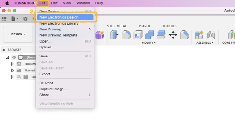
█ Step 2 - Create a New Electronics Design in Fusion 360.
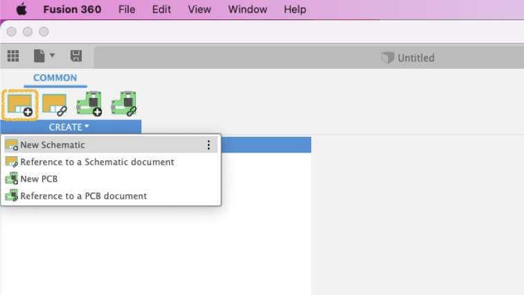
█ Step 3 - New Schematic in Electronics Design.
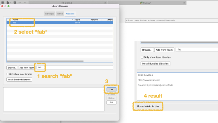
█ Step 4 - Open Library Manager.

█ Step 5 - Go to Available tag and browse fab.lbr.
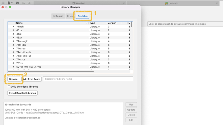

█ Step 6 - Search fab, then select fab on the list, finally click Use, you can see Moved fab to In Use.
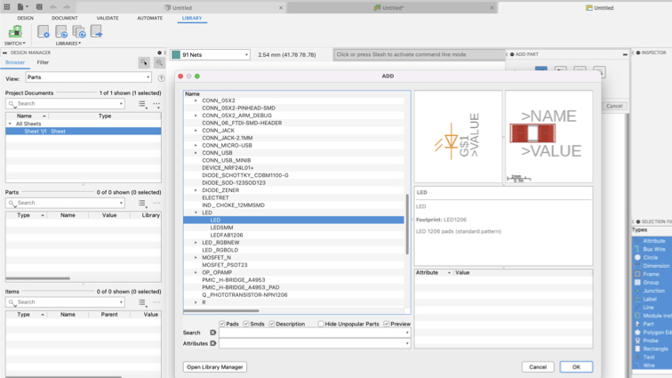
█ Step 7 - If you want to add some parts to schematic editor, press A key and select you want parts.
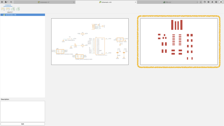
▼ This is my first Schematic.
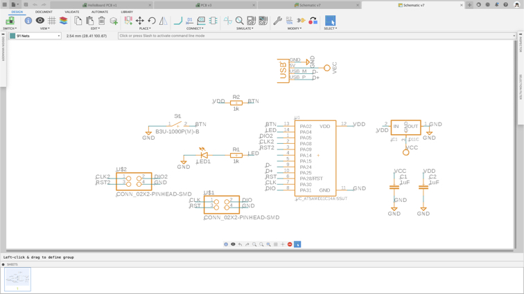
▼ A simple and clear way to connect signals, just give two signals same name, they will connect altogether.

Design the PCB
█ Step 1 - Switch to PCB document.
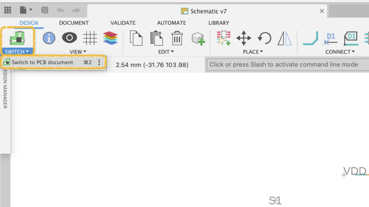
█ Step 2 - Choose PCB document.
█ Step 3 - You can move, rotate components. The thin gray line is the connection between the components in the schematic.
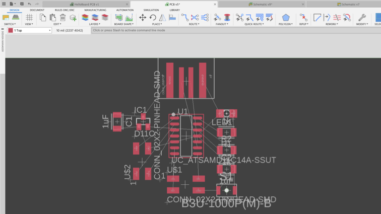
█ Step 4 - You can try Autorouter first.

█ Step 5 - Click Continue.

█ Step 6 - Click End Job after calculate. After Autorouter, you can still adjust the position of components and routes.

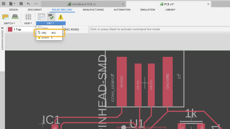
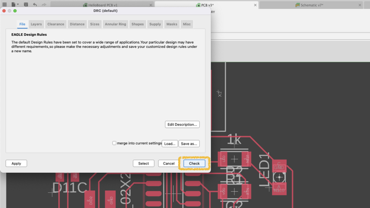
█ Step 7 - Next step is checking the PCB document is meet the FabLab requirements. Please click DRC in Rules DRC/ERC page.
█ Step 8 - Click Load and open fab.dru file.
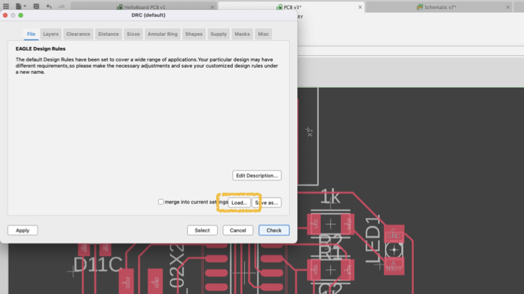

█ Step 9 - Click Check
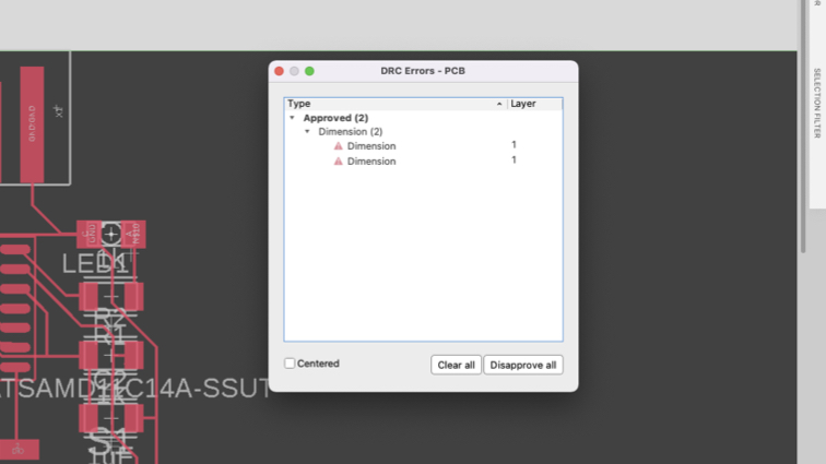
█ Step 10 - You can see the problem on your PCB.
█ Step 11 - I set all routes width to 12

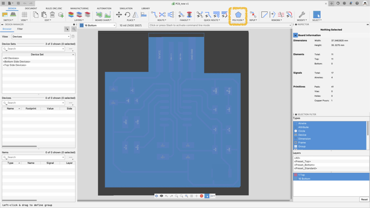
█ Step 12 - Use Polygon to create outline shape in layer 16.
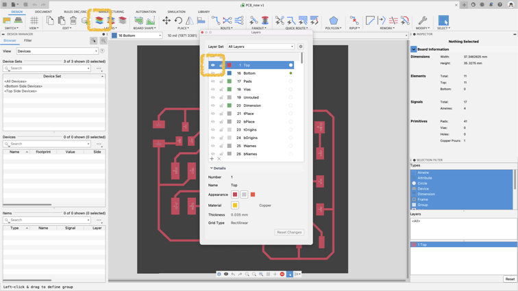
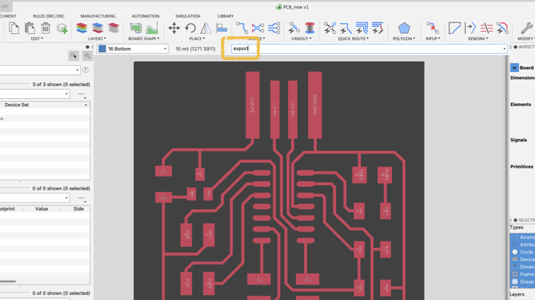
█ Step 13 - Click all layer button, and select traces layer or outline layer.
█ Step 14 - Enter export.
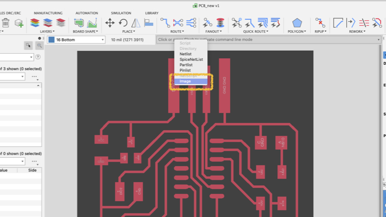
█ Step 15 - Then select image to export traces or outline layer to image.
█ Step 16 - Check Monochrome and set Resolution to 2000 dpi

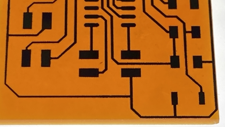
█ This is traces and outline image.

Milling and soldering
Export traces and outline .png file, and generate .nc file process same as week05. Also, I made the following adjustments to make the circuit beautiful.
- Rotating speed form 11000 rpm change to 10000 rpm
- Cutting speed from 3.5mm/s change to 2mm/s
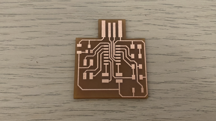
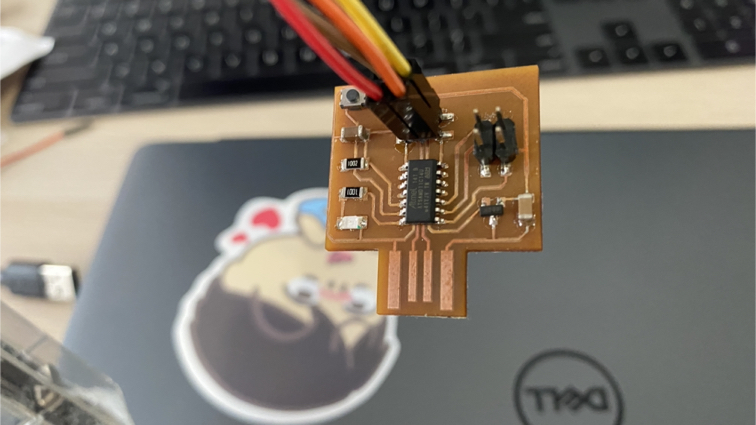
▼ This is my new PCB board.
▼ Check the circuits by multimemter.

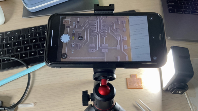
▼ Use ‘magnifier’ and light box to check again.
▼ Connect to the programmer through cable to prepare for the next step!
Programming
█ Step 1 - Burn firmware to PCB
Download sam_ba_Generic_D11C14A_SAMD11C14A.bin and edbg-windows-r29.exe.
Open command prompt, go to path for you downloaded file, and enter command.
edbg-windows-r29.exe -t samd11 -bpv -f sam_ba_Generic_D11C14A_SAMD11C14A.bin

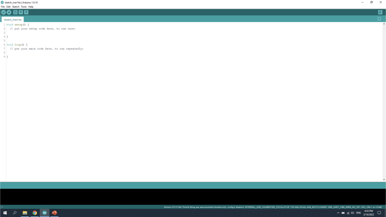
█ Step 2 - Open Arduino IDE
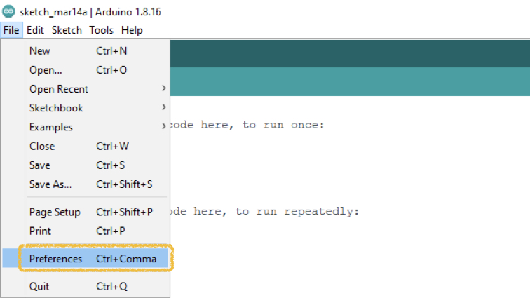
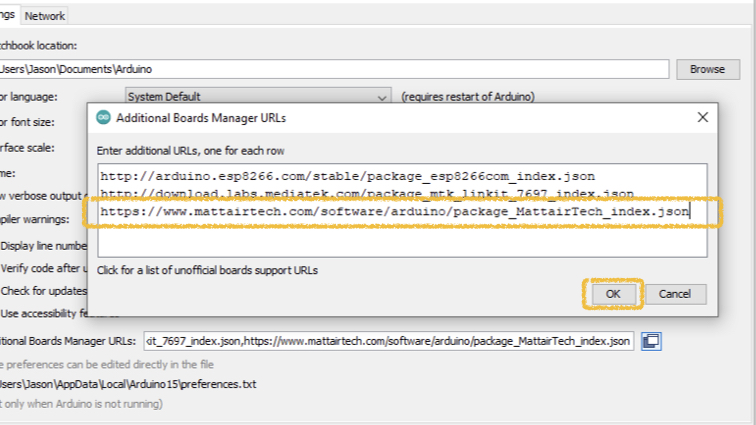
█ Step 3 - Arduino \ Prederences
█ Step 4 - Edit Additiona Boards Manager URLs

█ Step 5 - Enter URL
https://www.mattairtech.com/software/arduino/package_MattairTech_index.json
█ Step 6 - Arduino \ Tools \ Board \ Boards Manager
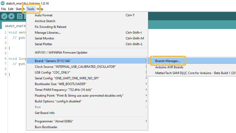
█ Step 7 - Search d11 and install lastest stable version.

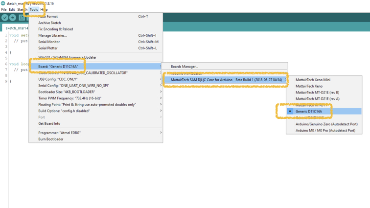
█ Step 8 - Arduino \ Tools \ Board \ MattairTech SAM DLC core for Arduino \ Generic D11c14A
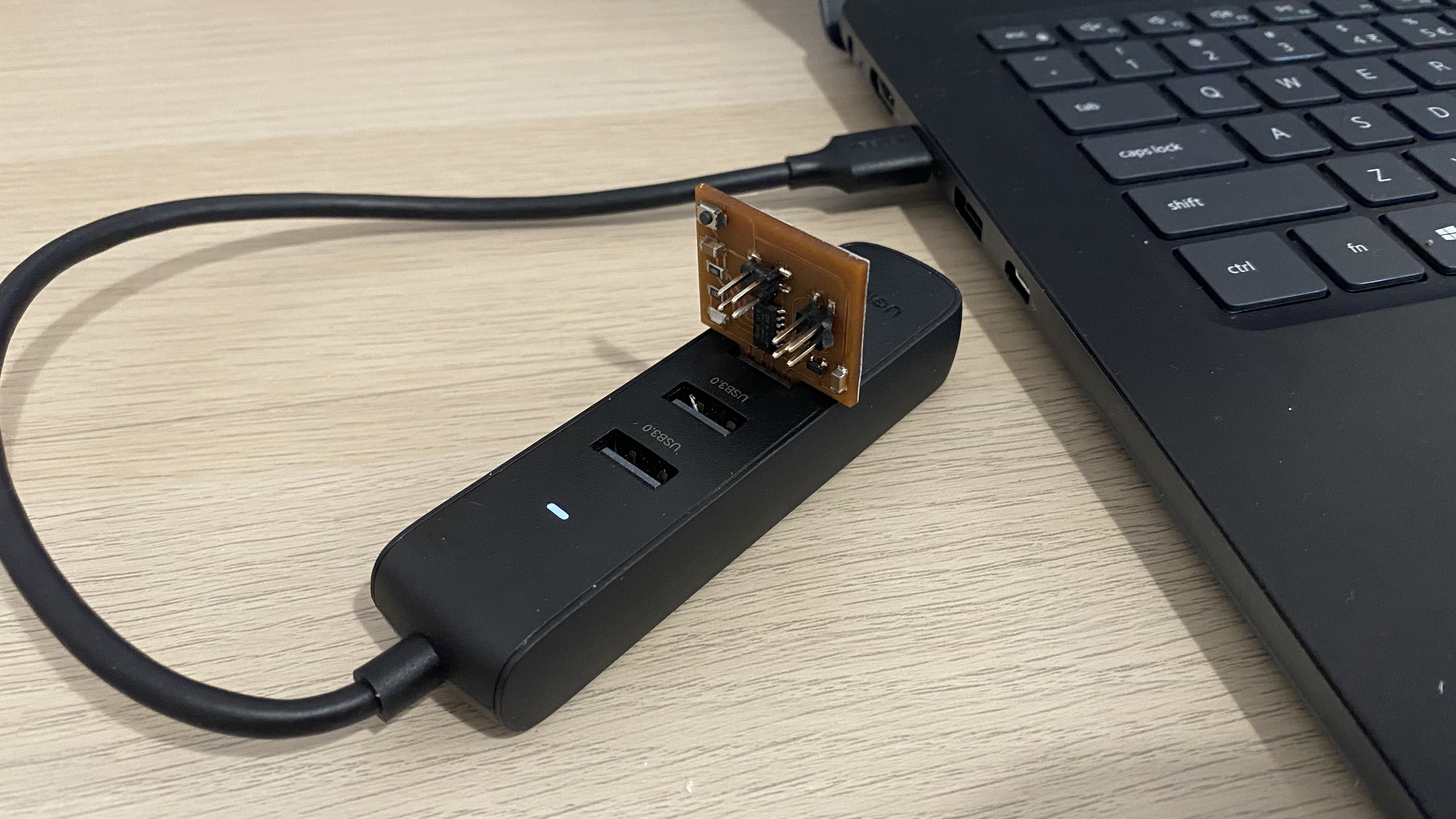
█ Step 9 - Plugin the board into USB hubs connected with computer.
█ Step 10 - Select correct port for board.

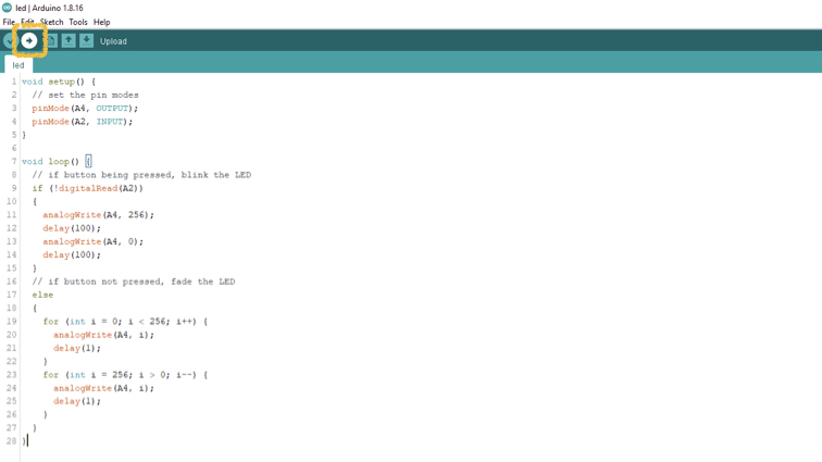
█ Step 11 - Write program for the board.
void setup() {
  // set the pin modes
  pinMode(A4, OUTPUT);
  pinMode(A2, INPUT);
}

void loop() {
  // if button being pressed, blink the LED
  if (!digitalRead(A2))
  {
    analogWrite(A4, 256);
    delay(100);
    analogWrite(A4, 0);
    delay(100);
  }
  // if button not pressed, fade the LED
  else
  {
    for (int i = 0; i < 256; i++) {
      analogWrite(A4, i);
      delay(1);
    }
    for (int i = 256; i > 0; i--) {
      analogWrite(A4, i);
      delay(1);
    }
  }
}
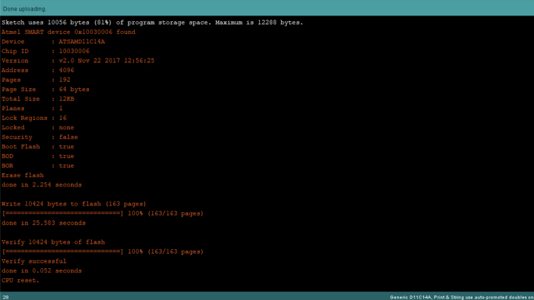
█ Step 12 - Press upload icon to upload program.
█ Sucessful upload the program!
Useful link and downloads
Download fab.dru and fab.lbr
https://gitlab.fabcloud.org/pub/libraries/electronics/eagle
Fusion 360 (3D CAD, CAM Platform on the cloud)
https://www.autodesk.com/products/fusion-360
Mods (Gen .nc file from image)
http://mods.cba.mit.edu/
EdytorNC (Communicate with milling machine)
https://sourceforge.net/projects/edytornc
Arduino IDE (Programming the board)
https://www.arduino.cc/en/software
Jason’s Edition PCB milling file
trace png file | outline png file
Arduino code - Blink LED
ino file