9. Embedded programming
This week Hero video!
This week Checklist
Group assignment
- [✓] Compare the performance and development workflows for different microcontroller families
- [✓] Document our work
Individual assignment
- [✓] Read the datasheet for the microcontroller I will programming
- [✓] Program the board I have made to do something, with as many different programming languages and programming environments as possible.
Group assignment
This week, our group will try to compare the performance and development workflows for different microcontroller families. Please click here to see more details of our group assignment.
Individual assignment
I will try to read the datasheet for the microcontroller I will programming - Atmel SMART SAM D11C
https://ww1.microchip.com/downloads/en/DeviceDoc/Atmel-42363-SAM-D11_Datasheet.pdf
SAM D11C microcontroller
SAM D11C is a low-power microcontrollers using the 32-bit ARM® Cortex®-M0+ processor, and ranging 14 pins with 16KB Flash and 4KB of SRAM. Operate at a maximum frequency of 48MHz.
▼ The Atmel SAM D11 devices provide the following features:
| Command | SAM D11C 14-pin SOIC |
|---|---|
| CPU | ARM Cortex-M0+ CPU running at up to 48MHz |
| Pins | 14 |
| GPIOs) | 12 |
| Flash | 16KB |
| SRAM | 4KB |
| Timer Counter | 2 |
| USB interface | 1 |
| Serial Communication Interface | 2 |
| Real-Time Counter (RTC) | Yes |
| RTC alarms | 1 |
| Packages | SOIC |
▼ Pin numbers of the SAMS D11C
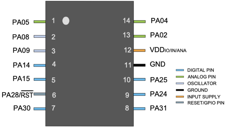
| IC pin | Port | Alternate Function |
|---|---|---|
| 1 | PA05 | RX2 / TCC01 |
| 2 | PA08 | TX1 / MOSI / TCC02 |
| 3 | PA09 | RX1 / SCK / TCC03 |
| 4 | PA14 | SDA / TC10 |
| 5 | PA15 | SCL / TC11 |
| 6 | PA28 | RST |
| 7 | PA30 | MISO / SWD / CLK |
| 8 | PA04 | REFB / TX2 / TCC00 |
| 9 | PA02 | DAC |
| 10 | VDD | |
| 11 | GND | |
| 12 | PA25 | USB+ |
| 13 | PA24 | USB- |
| 14 | PA31 | SS / SWD IO |
I learned from the data sheet
-
The size of the program is limited by the memory size of the microcontroller. (In-system self-programmable Flash)
-
Not every microcontroller have USB interface. If not, I need the FTDI cable USB-UART bridge and use the UART on board to connect to it USB. Lucky, Atmel SAMD11C built-in USB interface.
-
I found that it is possible to connect other control boards through the I2C port.
-
Some packages of same clip have more pins. Which package to use depends on the design needs.
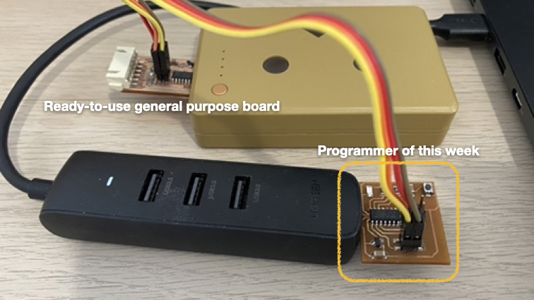
Use programmer to program other board
This week I need to prepare a ready-to-use general purpose board, similar to an Arduino.
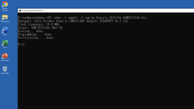
I connected programmer board and target board, and run command like week 07 assignment
edbg-windows-r29 -ebpv -t samd11 -f sam_ba_Generic_D11C14A_SAMD11C14A.bin
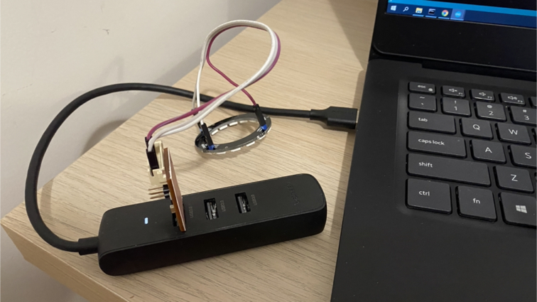
Use Arduino IDE Programming
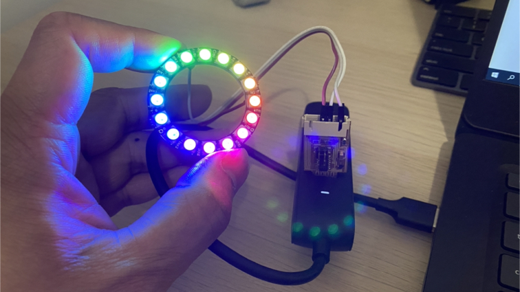
I’m using Arduino IDE and C++ language to write 2 program, first one is Rainbow.ino show a moving rainbow ring effect.
Arduino programming language reference
█ Step 1 - Connect board to USB hub.
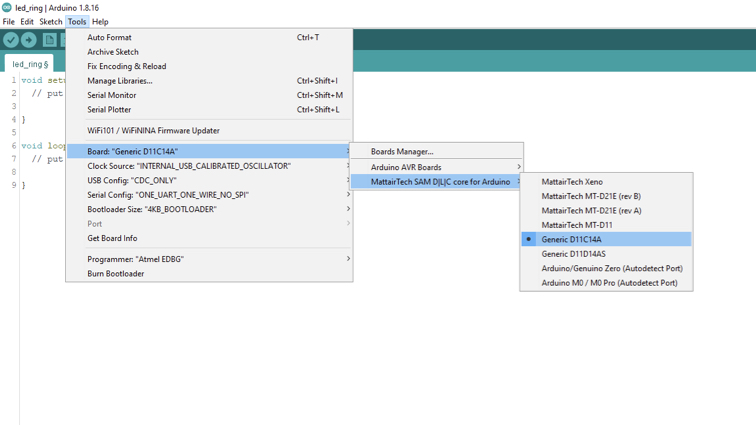
█ Step 2 - Arduino IDE \ Board \ MattairTech SAM DLC core for Arduino \ Generic D11C14A
█ Step 3 - Arduino IDE \ Sketch \ Include Library \ Manage Libraries

█ Step 4 - Search neopixel and Install Adafruit NeoPixel by Adafruit.

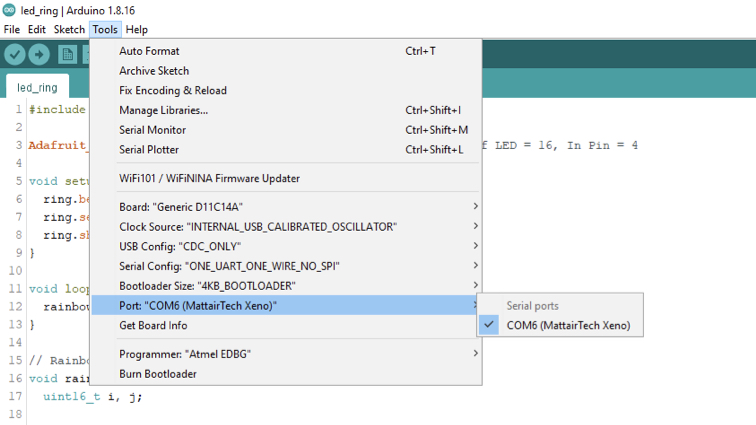
█ Step 5 - Select correct com port to connect board.
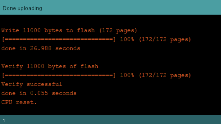
█ Step 6 - Upload the program.
█ This is a Hero shot for my rainbow ring program.
▼ Rainbow.ino
#include <Adafruit_NeoPixel.h>

// (Number of LED = 16, In Pin = 4
Adafruit_NeoPixel ring = Adafruit_NeoPixel(16, 4);

void setup() {
  ring.begin();
  ring.setBrightness(32); // Brightness 0 to 255
  ring.show();
}

void loop() {
  rainbowCycle(10); // Rainbow effect
}

// Rainbow effect
void rainbowCycle(uint8_t wait) {
  uint16_t i, j;

  for (j = 0; j < 256 * 5; j++) {
    for (i = 0; i < ring.numPixels(); i++) {
      ring.setPixelColor(i, Wheel(((i * 256 / ring.numPixels()) + j) & 255));
    }
    ring.show();
    delay(wait);
  }
}

uint32_t Wheel(byte WheelPos) {
  WheelPos = 255 - WheelPos;
  if (WheelPos < 85) {
    return ring.Color(255 - WheelPos * 3, 0, WheelPos * 3);
  }
  if (WheelPos < 170) {
    WheelPos -= 85;
    return ring.Color(0, WheelPos * 3, 255 - WheelPos * 3);
  }
  WheelPos -= 170;
  return ring.Color(WheelPos * 3, 255 - WheelPos * 3, 0);
}
▼ Another one is servo.ino demo how to use PWM to controll servo motor.
▼ Rainbow.ino
//Initializing Servo Pin
int servo_pin = 4;
void setup() {
  //Declaring Servo pin as output
  pinMode(servo_pin, OUTPUT);
}
void loop() {
  for(int i=0; i<255; i++){
    analogWrite(servo_pin, i);
    delay(5);
  }
  for(int i=255; i>0; i--){
    analogWrite(servo_pin, i);
    delay(5);
  }
}
Met problem

I have tried connecting a MAX7219 8x8x4 LED Matrix but found that the current provided by the USB is not enough to propel the component, although I guess an external power supply can be connected but I still haven’t found a sure way to do it.
Try other development methods
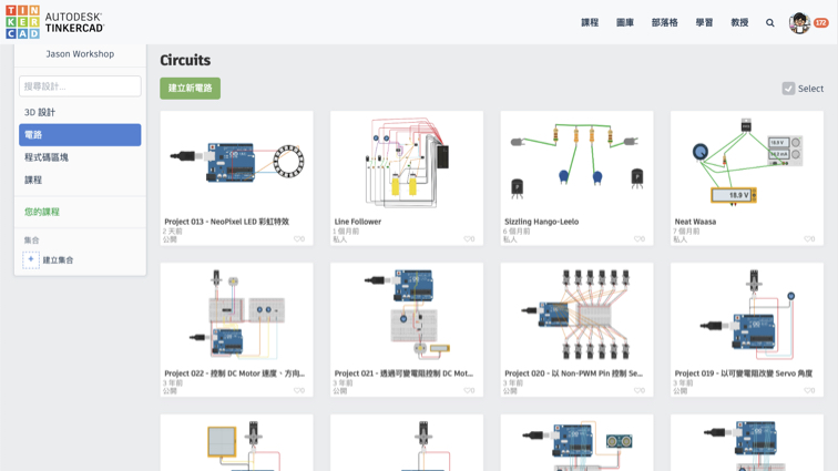
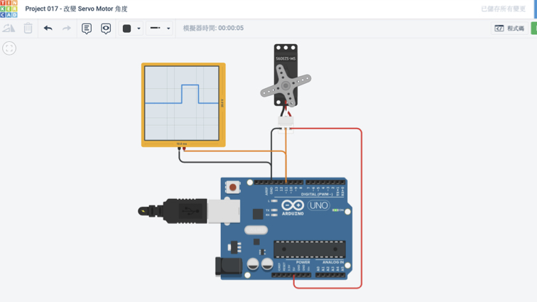
At some time I want to be quickly write a program and test its feasibility, I will use Circuits in TinkerCAD. It is a web-based circuit simulator, not too many components available, but also a great learning tool for beginners.
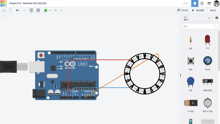
▼ Freely connect various components to facilitate testing whether the circuit is feasible.
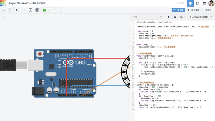
▼ Use the C++ programming language and write directly on TinkerCAD Circuits.
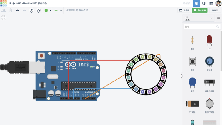
▼ This is the output of the simulation.
▼ You can connect an analog oscilloscope to understand what is PWM.
Useful link and downloads
Useful link
Arduino programming language reference
TinkerCAD
My projects on TinkerCAD
Burn program to board
edbg-windows-r29.exe
Bin for the board
free_dap_d11c_mini.bin for programmer board
sam_ba_Generic_D11C14A_SAMD11C14A.bin for my target board
Source code
Rainbow.ino
servo.ino