11. Output devices
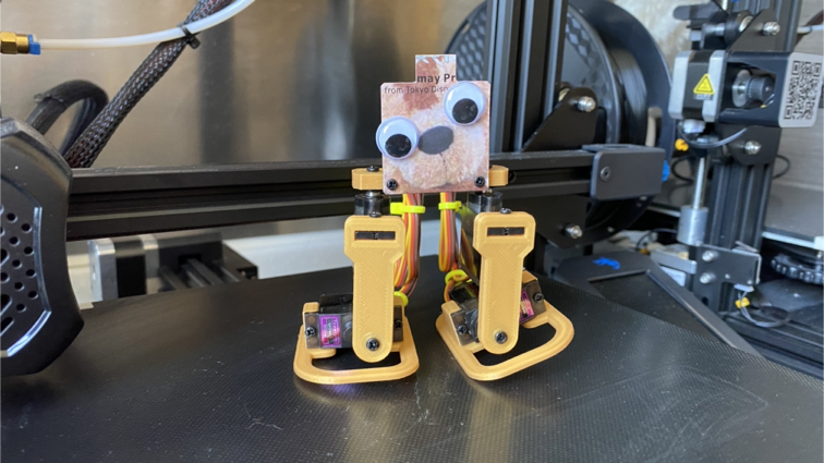
This week Hero shot!
This week Checklist
Group assignment
- [✓] Measure the power consumption of an output device.
- [✓] Document our work.
Individual assignment
- [✓] Add an output device to a microcontroller board I’ve designed and program it to do somrthing.
Group assignment
This week, our group try to measure the power consumption of an output device. Please click here to see more details of our group assignment.
Individual assignment
In this week, I would like to design a 4 DOF little robot to explore output device.
Design new PCB and 3DP parts for my little robot
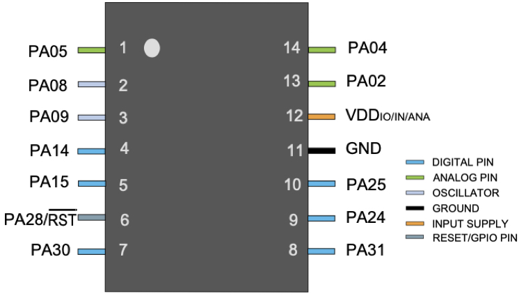
▼ Recap the pin of the microcontroller first.
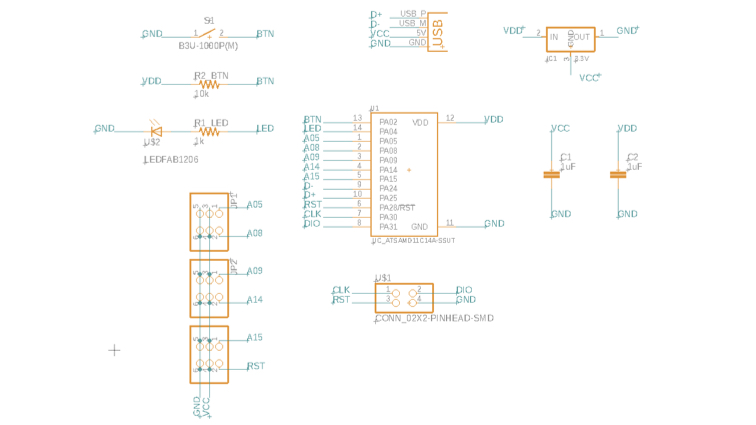
▼ Redraw schematic for practice.
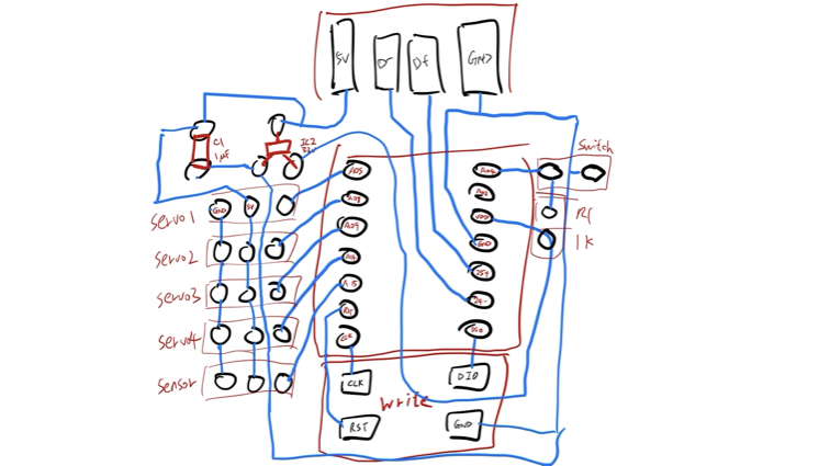
▼ This is my draft of new PCB.
▼ Redraw PCB and route.
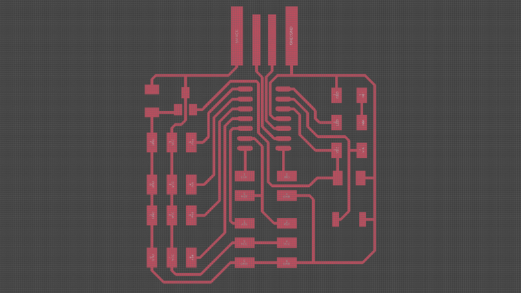
▼ This is remark on PCB.
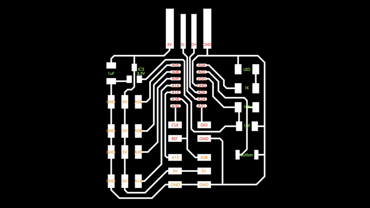
▼ Component List
| Component | Quantity |
|---|---|
| Atmel SAMD11C14A | 1 |
| 3.3v regulator | 1 |
| 1 uf capacitor | 2 |
| 1k resistor | 1 |
| 10k resistor | 1 |
| LED | 1 |
| 2x2 Pin header | 1 |
| 2x3 Pin header | 3 |
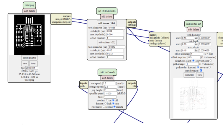
▼ Use mod to create PCB trace and outline nc file.
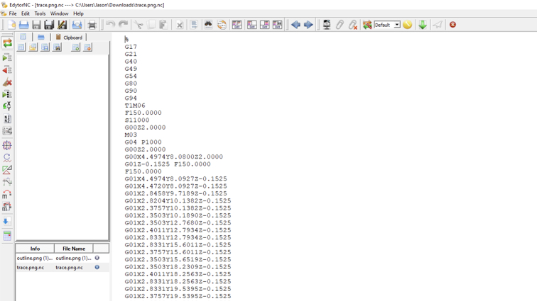
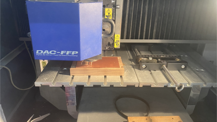
▼ Send nc file to milling machine.
▼ Start milling!
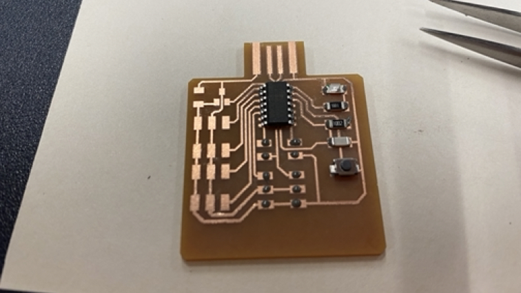
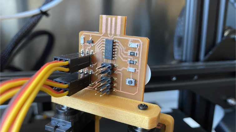
▼ Soldering PCB and use command to burn bootloader to PCB.
edbg-windows-r29 -ebpv -t samd11 -f sam_ba_Generic_D11C14A_SAMD11C14A.bin
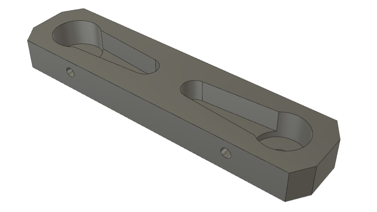
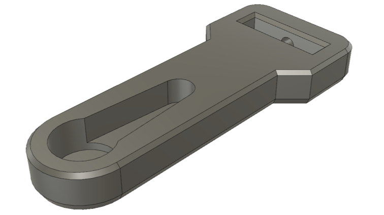
▼ Use Fusion 360 to design 3DP parts for robot.
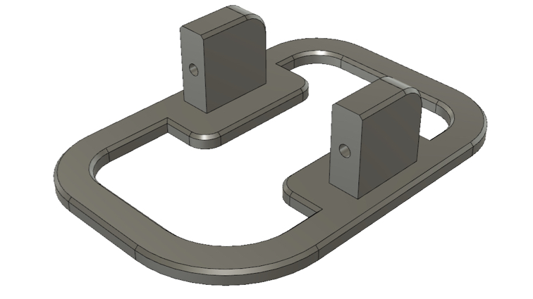
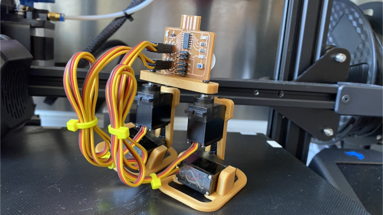
▼ Yeah! This is my little robot!
Programming my little robot
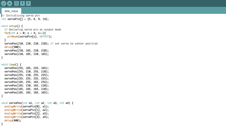
▼ I’ve using Arduino IDE to write the program for robot, and I make a function for change servo position, simplifies and keeps program clean.
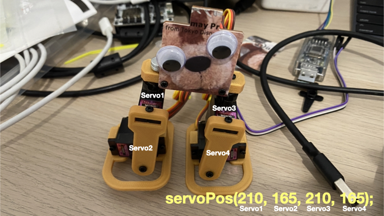
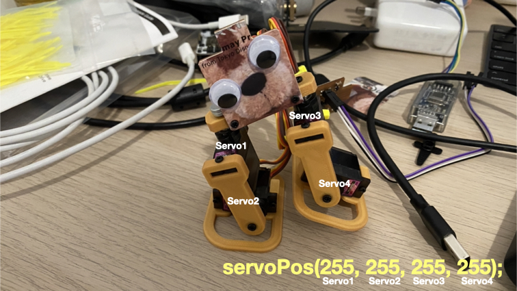
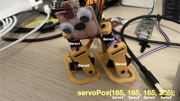
▼ I want little robot can walking, so I need to design action flow. This is servo location and PWM of servo rotate angle.
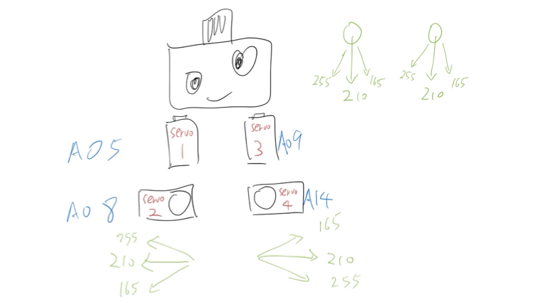
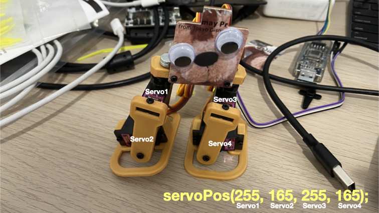
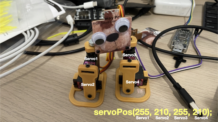
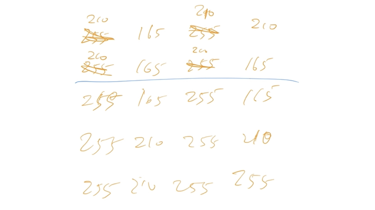
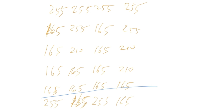
▼ I need to place actions frame by frame and record the PWM values for each servo motor.
▼ Here are the notes I took while recording the action.
▼ Finally I put the action into the program and it’s done.
// Initializing servo pin
int servoPin[] = {5, 8, 9, 14};

void setup() {
  // Declaring servo pin as output mode
  for(int s = 0; s < 4; s++){
    pinMode(servoPin[s], OUTPUT);
  }
  servoPos(210, 210, 210, 210); // set servo to center position
  delay(500);
  servoPos(210, 165, 210, 210);
  servoPos(210, 165, 210, 165);
}

void loop() {
  servoPos(255, 165, 255, 165);
  servoPos(255, 210, 255, 210);
  servoPos(255, 210, 255, 255);
  servoPos(255, 255, 255, 255);
  servoPos(165, 255, 165, 255);
  servoPos(165, 210, 165, 210);
  servoPos(165, 165, 165, 210);
  servoPos(165, 165, 165, 165);
}

void servoPos(int a1, int a2, int a3, int a4) {
  analogWrite(servoPin[0], a1);
  analogWrite(servoPin[1], a2);
  analogWrite(servoPin[2], a3);
  analogWrite(servoPin[3], a4);
  delay(400);
}
▼ I try to use DC Power Supply nps306w to monitor the current when robot walking.
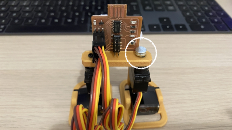
A small problem
▼ A small problem I encountered is that the balance of the body was not considered when designing this robot. Now I have to add weight for first aid. I will remember to consider the balance of the body when designing in the future.
Downloads
This week PCB trace png file | outline png file | remark on PCB
Robot’s 3DP parts (f3d format) base | leg | foot
Robot’s 3DP parts (stl format) base | leg | foot
Robot’s Arduino Code little_robot.ino