10. Output devices
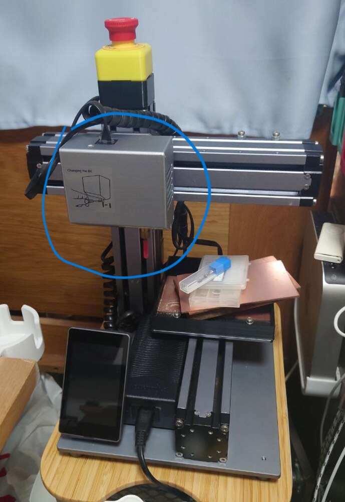
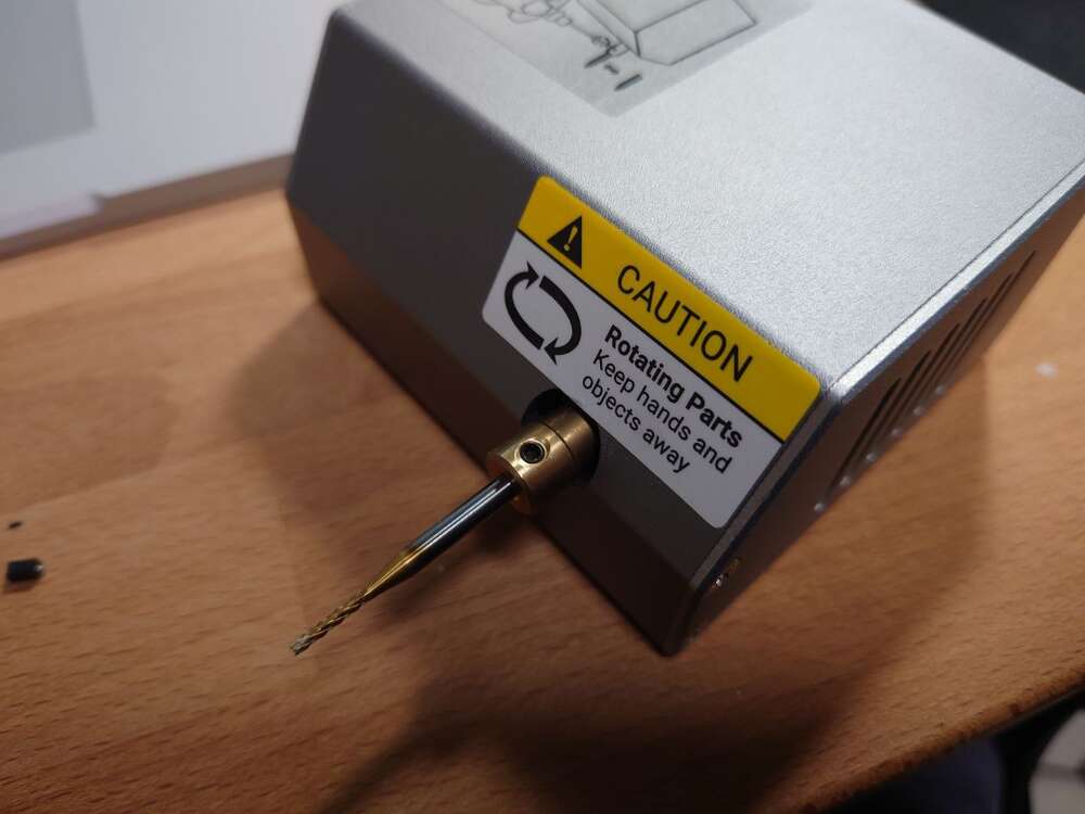
This week I started making PCB at my home with the 3-in-1 machine from Snapmaker(3D printing, CNC milling, and laser engraving). I mainly used its CNC module for milling my boards. However, the CNC module uses a copper coupler for mounting the bits to the motor and it vibrates so strongly. I am not able to make a PCB with this shaking bit. So I designed a new CNC module for my Snapmaker 3-in-1 machine, and made a MOSFET driver to test the motor on the new module with a board I made previously.
Things needed to improve
- Vibration
- Ability to vary the speed
ER11 Chuck on DC Motor
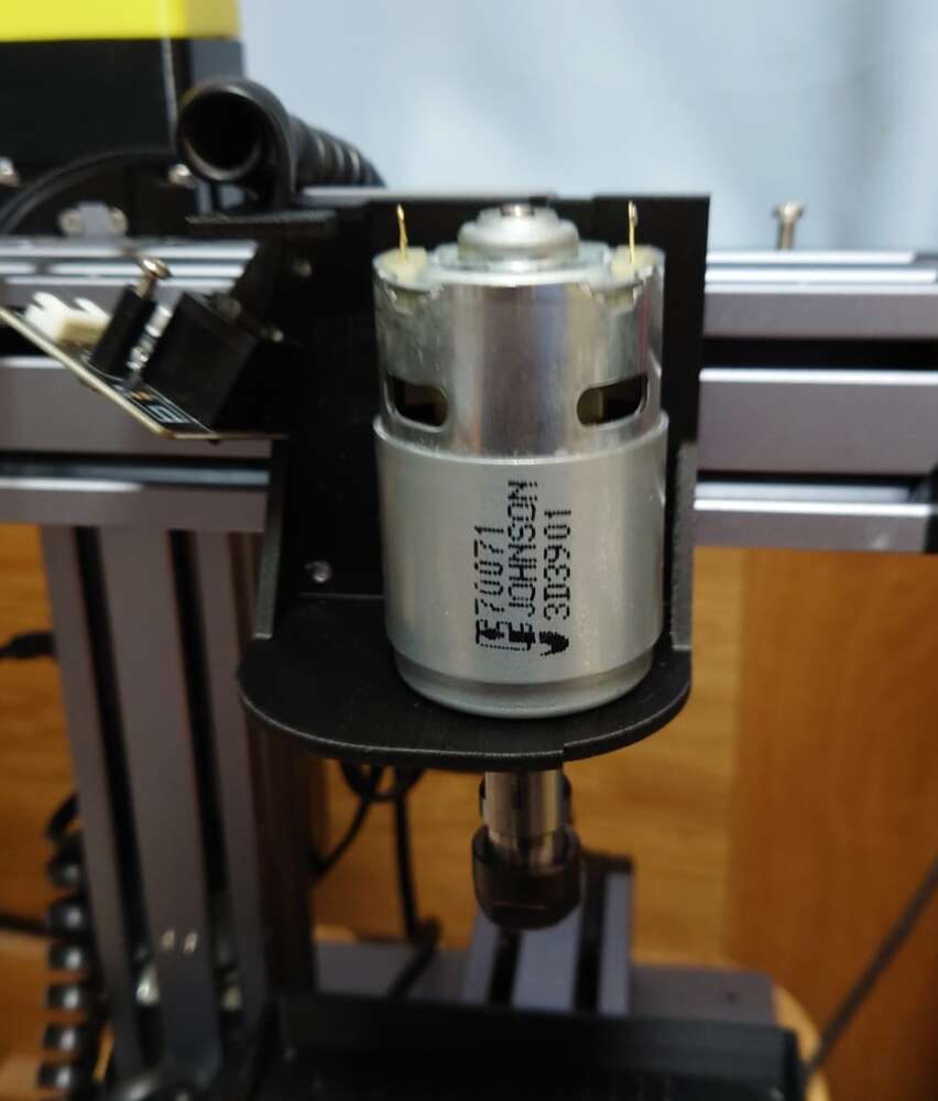
I bought a 775 DC motor and a ER11 Chuck mounted on its 5mm shaft. This chuck was commonly used in many CNC milling machines and known has good precision. I think it’s precise enough to mill PCB boards.
The MOSFET driver
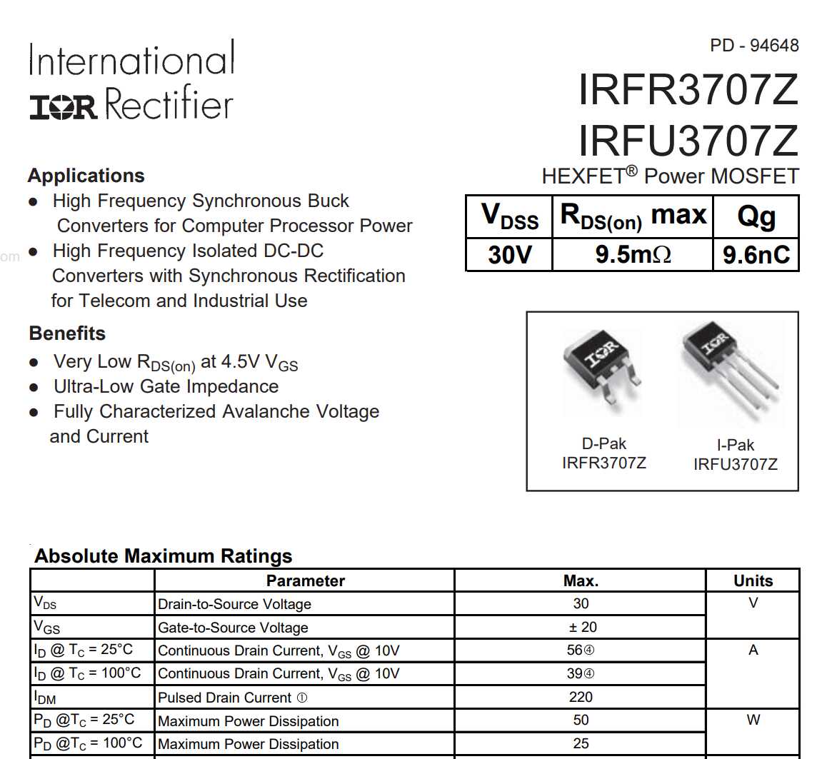
To drive this giant DC motor in different speed, I designed a MOSFET driver with IRFU3707Z MOSFET that I have. This MOSFET has very low RDS(on) at low voltage which suitables for low voltage signal such as micro controllers output.
Schematic
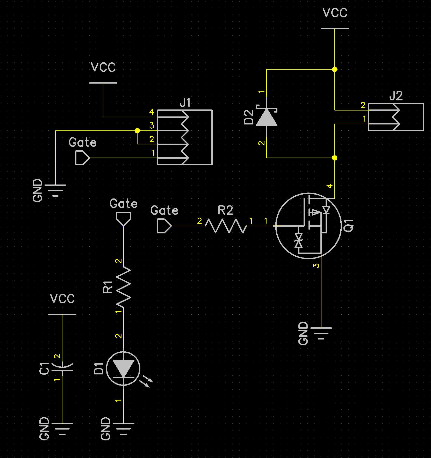 It’s a common low-side drive MOSFET driver which the motor was designed to connect to J2. An LED(D1) was added to indicate the Gate signal status. A flyback diode(D2) was used to protect the circuit from back-emf.
PCB layout
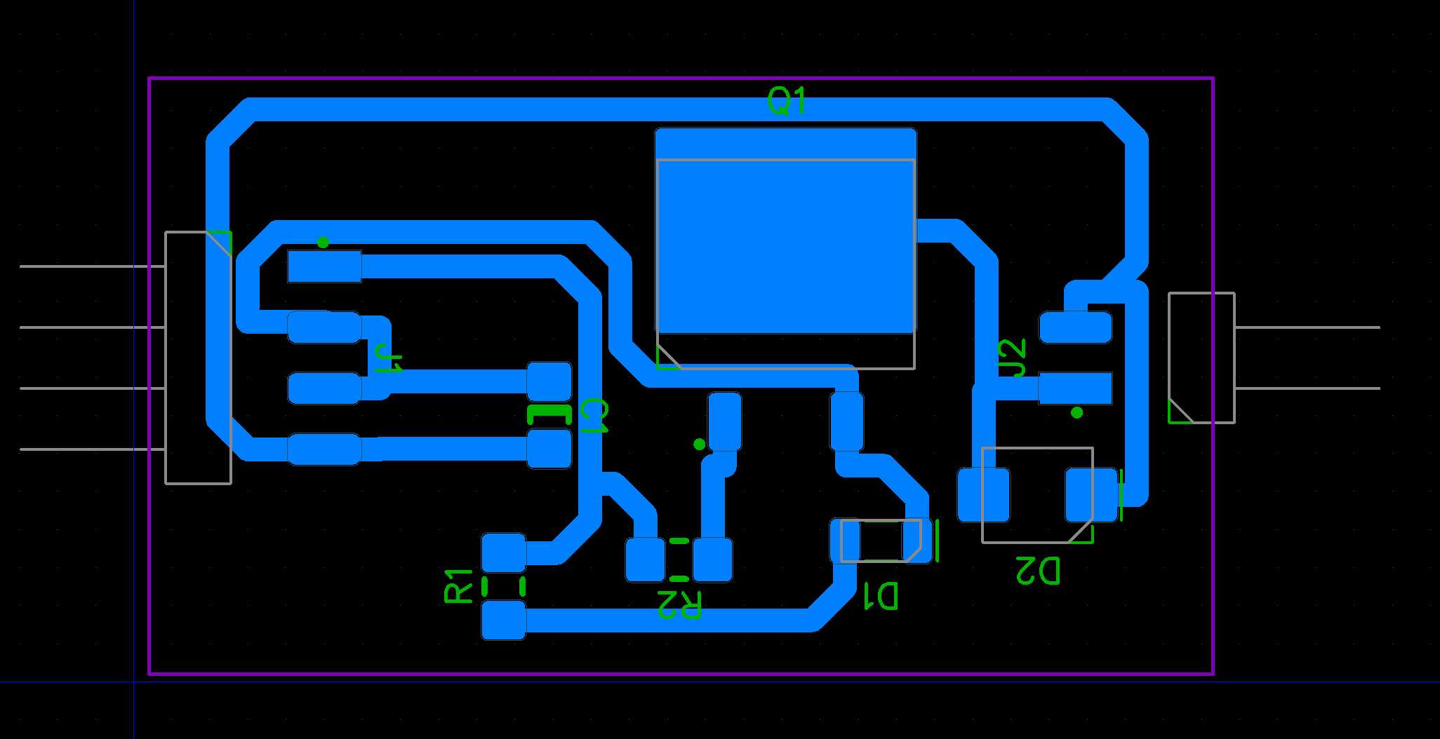 The trace width were set to 1mm, it allows them being able to carry higher current and helps the milling process easier to success.
PCB
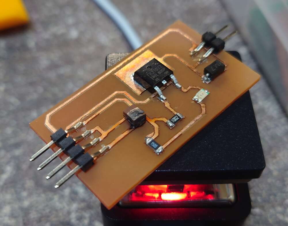 I milled the PCB board and solder the components on it, check out week4 to see more details of the process.
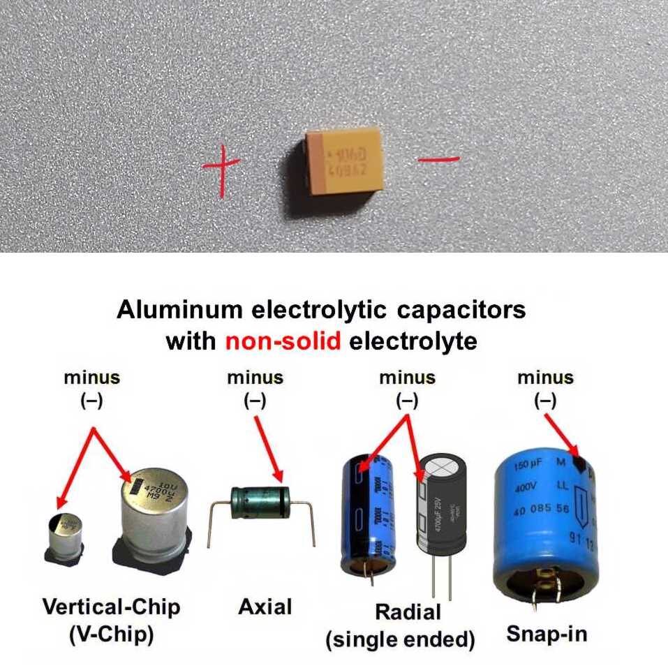
Problem Met - Polarity reversal of tantalum cap
The home-made PCB with components soldered on it. The tantalum capacitor on the left hand side was burned because I mixed up with the polarity. Normally the mark on a capacitor’s negative side, but the mark on tantalum capacitor was at its positive side. Anyway, only the capacitor hurnted during my first attemp to provide power to the board. I replaced the burned capacitor after that.
Testing with SAMD11C
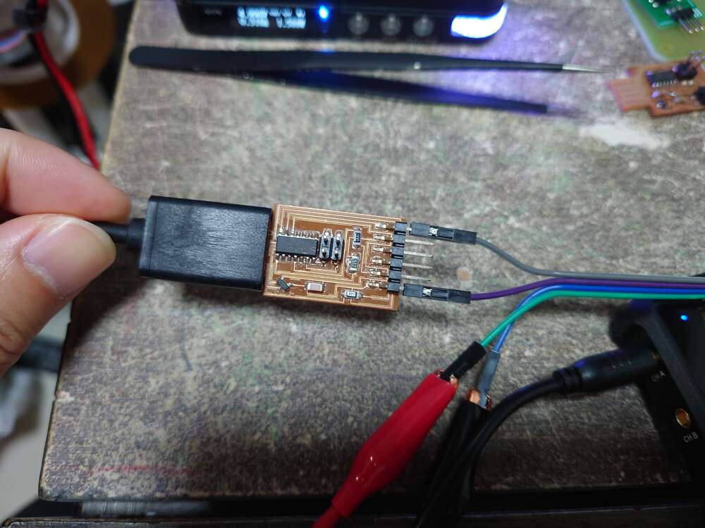 To test the motor with the MOSFET driver, I used the board made on week4 to generate a pwm signal.
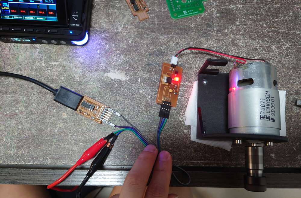 The board with SAMD11C was powered by usb port, its P02 pin was connect to the Gate pin of the MOSFET driver. A DC 12V external power was provided.
The program
To test how different PWM parameters affect the motor, the program first generate 10% duty cycle at different frequency(100Hz to 3.2kHz). Then the frequency fixes at 3.2kHz, the duty cycle increase from 10% to ~100%.
//Timer settings
unsigned long previousMillis = 0; // will store last time PWM was updated
const long interval = 2000;      // interval at which to change PWM value (milliseconds)

//PWM settings
int motorPWM_Pin = 2; // the PWM pin the motor is attached to
int duty = 10; //pwm duty cycle in %
int freq = 100; //freq in Hz


void setup() {
  pinMode(motorPWM_Pin, OUTPUT);
}

void loop() {
  unsigned long currentMillis = millis();
  if (currentMillis - previousMillis >= interval) {
    if (freq < 3200)
      freq *= 2; //double up the frequency
    else if (duty < 100)
      duty += 10;
    else { //reset the freq and duty
      duty = 10;
      freq = 100;
    }
    previousMillis = currentMillis;
  }
  digitalWrite(motorPWM_Pin, HIGH);
  delayMicroseconds(1000 * 1000 / freq / 100 * duty);
  digitalWrite(motorPWM_Pin, LOW);
  delayMicroseconds(1000 * 1000 / freq / 2 / 100 * (100 - duty));
}