11. Output devices
This weeks assignment was to design, mill, and program a micro controller board that would operate a output device.
Chosing What Output To Use:
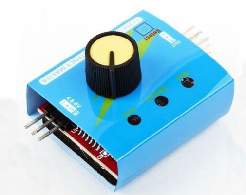
I wanted to do something for my final project this week. My final project is an advanced VTOL aircraft so it has quite a few outputs ranging from the servos that operate the control surfaces, to the many moters that provide the aircraft with the sufficent power to fly. At first I decided to go with an ESC tester. I already had an idea of what power moters I would be using and the corrosponding battery and speed controlers. These were A 40 Amp ESC for the pusher Moter, and 30 Amp ESC’s for each of the VTOL moters. At first I thought this was a really good idea but the more I thought about it, the more I relized that it was not very viable. In my experience with rc aircraft, it is alot easier to test the escs ust by hooking the up to the reciver rather then a fancy testing board. Because of this I ended up Shifting my Focous to servos. A servo tester would be very helpful because it is impossible to tell the exact centerpoint without hooking it up to a power sorce. and unlike a esc which either works or does not, if the servo horn is not centered you need to remove the servo from the aircraft, fix it, then re install it. a servo tester removes the need for this and I would actually use it when constructing my final project. After doing a bit of research I learned that it was 100% viable to create and program a servo tester on a attiny412 using a 10k POT.
Creating A Tester:
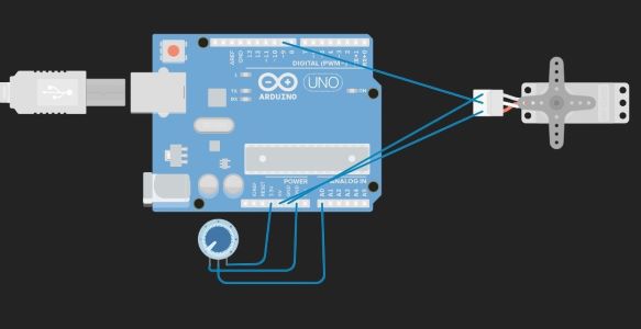
To begin I started by creating a rough circut of the servo tester in TinkerCad. The circut was very simple as it just involved a servo routed to a 5v power pin, signal PWM pin, and ground pin on the arduino. Additionally the circut also had a 10K POT routed to a 3.3v power pin, signal pin with PWM, and a ground pin.
With the servo tester circut created, I needed to write a program that would actually make it work. After around 30 minuites and a few searches, I got a program that worked up and running using arduinos build in Servo library. Here is the code I used:
#include <Servo.h>

Servo myservo;

int potpin = 0;
int val;

void setup() {
  myservo.attach(9);
}

void loop() {
  val = analogRead(potpin);
  val = map(val, 0, 1023, 0, 180);
  myservo.write(val);
  delay(15);
}
Before I could check off on tinker circut I needed to make sure that the library that I was using would also work on an AtTiny 412 chip. Luckely to my shock and supprise the library was actually compatable. It was nice to have something go right for once with programming.
Creating The Schematic In KiCad
Now that I knew my circut was programmable and running, I was ready to begin creating the Schematic for it in KiCad. To do this I used the Schematic that was created in TinkerCad based off the circut I built. Here is a photo of what the TinkerCad Schematic looks Like:

Because I was using the same chip as I have used before, I decided to make a copy of my first blink board schematic and just change the output section of it. Here is a photo of what my first blink board schematic looks like:

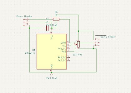
With the output section of the blink board removed I began adding the components for the servo tester. First I added a 10K POT and connected it to a Power, PWM, and Ground pin. Then I added a second 3 pin header. This header would be where I would connect the servo to the tester. Here is a photo of what the finished Schematic looks Like:
Creating the PCB:
Now that I had the schematic created I could begin working on positioning and setting up the traces in the PCB editor. This process was very similar to how I created my PCB during Electronics design week. If you would like to learn more about how I generally create PCBs check out my Electronics design documentation. I was actually very luck with this as I positioned everything in a way that worked on my second attempt. Additionally I had no errors when I ran the PCB checker. Here is a photo of what my Finished PCB looks like in the PCB editor:

Milling My Board:
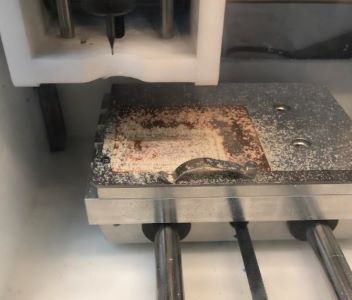
With the PCB design ready, I plotted it and sent both the main cut and edege cuts to the bantam software. From there I set up the correct configigurations and positined the cut. If you would like to know more abut how I mill please refer to my electronis production week as I go more indepth about milling there. Here are some Images of the milling process:


Soldering The Board:
After purging the board of any lose copper shavings and saawdust, I began collecting my materials. My materials Consisted of:
- 1x AtTiny-412
- 2x 3Pin Horozontal Headers
- 1x 1uf capacitator
- 1x 0 Ohm Resistor
- 1x 10 K POT
- 1x Milled PCB
With my materials Gathered I began to solder my board. At this point I have become extremly skilled at surface mount soldering so I was able to knock this out In about 20 minuites. Here is an Image of the compleated Board:
Testing The Board:
Im going to be honest, I had Littile faith that this would actually work. This was because everything had gone so smoothly up until this point. First I got my programmer out and wired it to the servo tester PCB. I was worried that something was not right so I was holding my finger on the attiny when I plugged it into my laptop. as soon as the programmer was plugged in and teh code was uploaded, the At-Tiny on the servo tester PCB started rapadly heating up. I immiedatly unplugged it to prevent it from frying and after a few more attempts relized it was hopless. Here is an image of the first failure wired to the programmer:

Re-Creating the Schematic
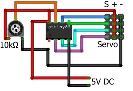
After the incident of almost frying the At-Tiny, I hopped back into the Ki-Cad PCB shematic editor and began making changes. I stumbled across this really good image online that I was basing my schematic off of. The image did use a At-Tiny 85 insted of a 412 but I compared the pinnouts of both chips and accordingly made the changes to what went where. Here is a screenshot of the image I found:
After a bit of ajustment to my first Schematic, I ended up with something looking A bit like This:
Re-Creating The PCB
Now that I had the (I Think) Fixed schematic, I brought it into the PCB editor and began making the new PCB. I also got reletivly lucky with this PCB as I did not need to jump any traces with a 0 ohm resistor and got it in a configuration that worked on my third try. Here is an image of the Finished Second PCB in the PCB editor:

Re-Milling The PCB
Now that I had everything re-designed It was time to mill.... again. This was a quick and easy process and nothing eventful happened.
Soldering The PCB
Similar to the first time, soldering was no struggle and within around 10 minuites I had it finished. Here is what the finished Soldering board looked like:

Oh-No Volume 2:
To make sure that I would not fry anything this time I did one last check over and relized that I overlooked one very important factor. My PCB did not have a ground. So I threw it into my pile of failed boards and was back to the drawing board.
Planning My PCB Again:
If im being honest, by this point I just wanted to be done with the servo tester. To start I drew up a schematic on a peice of paper. This way I was sure I was checking the boxes for everyting related to the Attiny. After a few changes here and there and a few crumpled balls of paper in the trashcan, I came to a schematic that I was happy with. Here is what that schematic looks Like:

KiCad For A Third Time:
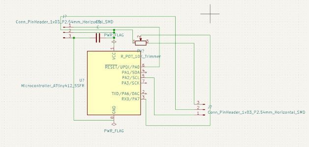
Now that I had my schematic drawn up on paper I needed to transfer it to KiCad. I started with the AtTiny-412 and connect the wires accordingly to the servo header and the 10K POT. Then I checked over it about 20 times. After verefying everything was good I added the UDPI header along with the 1uf capacitator to help stabalize the current going into the AtTiny-412. I ended Up with a schematic looking like this:

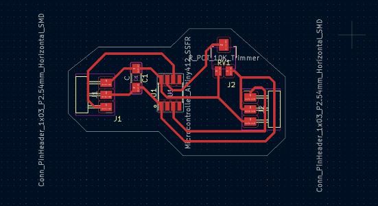
With the schematic created in KiCad It was time to hop on into the PCB editor for a third time. I payed close attention while creating the PCB in the PCB editor. I was closly comparing it the the current schematic that I had drawn up on the peice of paper. After around 20-30 minuites I had a PCB That looked something like this. On a side note I decided to do my edege cuts a diffrent way and think I like how it looks alot more.
Milling And Soldering The Third Attempt:
After around a hour of staring at the Board on my screen and looking for anyting that would cause a issue, I plotted it and sent it to the othermills. Milling the board was uneventful as before. Again if you would like to learn more about how I mill PCB’s check out my electronics production documentation. Once the board was off the miller, I cleaned it up and began gathering my components. I was still using the same components as before. I began soldering it and in the end i had something looking a bit like this:

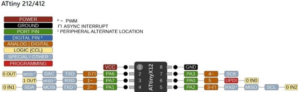
Now was the moment of truth, I hooked it up to my programmer and pluged it in to my comuter. I had my finger on top of the AtTiny-412 and it wasent heating up so i knew that i had the power pins set up correctly. I opened up the ArduinoIDE and pasted this code from tinkercircut into the arduino editor. I then made some appropiate changes that invloved me changing the pinnouts from arduino pins to AtTiny-412 pins. Here is a photo of the DataSheet I used to find the pinnouts:
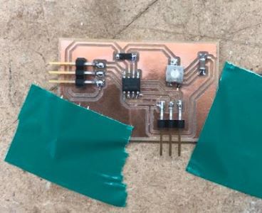
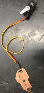
I then plugged the servo into the servo tester and hit the upload button. After watching the green upload bar progress i heard the servo activate. Then I started turning the 10K pot and to my utter supprise It actually Worked! I ended up playing with it for about five minuites in pure shock. Here is an image of what the Finished Circut Looked Like:
Here is the code that i used to make the servo tester.
#include <Servo.h>
Servo myservo;

const int servoValu = 1;
int mode = 0;
int val = 0;
int potpin = 4;


int pos = 0;
int servoVal =0;
int potVal;

void setup ()
{
  Serial.begin(9600);
  pinMode(servoVal, INPUT);
  myservo.attach(1);
 }

void loop () {


    mode=0;
    delay(15);
    potVal = analogRead(potpin);
    potVal = map(potVal, 0, 1023, 0, 180);
    myservo.write(potVal);
    delay(15);
    Serial.print("  potVal : ");
    Serial.println(potVal);

}
On a side note thanks to fellow fab academy student Nick Niles for giving me the idea to run my AtTiny of a 9v battery. To my supprise it actually worked and did not fry the chip.
Conclusions:
Overall I learned alot about how electroinics worked this week and also learned how to change what chip a program can run off of. I learned more about analizing datasheets.
Here is a link to my PCB Files from this week!
Group Site
Here is the link for the group site. Aarush and I tested the power consumption of my servo tester reletive to its positning.