4. Electronics production
This week we needed to have soldered an AT-Tiny board and a UDPI Programmer.
Assignment 1: Soldering a At-Tiny Board:
This project was to get a LED to blink by using the standered arduino BLINK code. However it was not that easy. Insted of running it on an arduino, we needed to convert the arduino into a boot loader and run the program on an AT Tiny 412 Chip.
Setting up the software
To convert the Arduino UNO into a bootloader I needed to install a couple of things. First I installed the jtag2updi library. This file contained the code I needed to run on the arduino in order to make it a bootloader. It was reletivly easy to do as I just downloaded the file, extracted it, and ran the arduino sketch found inside. Upon opening the sketch i was presentew with a bunch of tabs, one of which was blank. To convert your arduino, make sure it is pluged in to the right USB port and then run the blank tab of the sketch. Additionally I needed to install the software for the 412 chip. This was easy as under board manager in the Arduino editor i just searched Mega tiny and Installed the one made by Spence Konde. Next under Prefrences I pasted this link under Additional Board Manager URLs “http://drazzy.com/package_drazzy.com_index.json”. I have no idea what this does but I was told I needed to do it so I did.
Soldering the Board
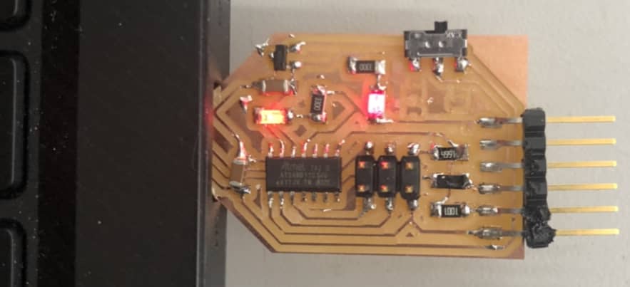
After I converted the Arduino UNO to a boot loader I needed to solder the AT Tiny 412 Chip, A LED, 6 Headers, a 499 Ohm Resistor, a 4.99KOHM Resistor, And a capcitor to a small pre-milled board. The first challange of this process was actually interpreting the board. contrary to what I thought the quote unquote wiring is not what was milled but what wasent milled. After learning this I was able to orient the board and gather my supplies easly. The soldering went without much trouble and I was able to finish it quickly and efficetivly only needing to re-solder one of the 6 headers. Here are some images depicting the process I went through to solder the board together.
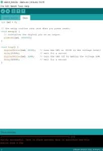
Setting up the BLINK code
This part of the process was very easy as it was basically just copying and pasting the standered Arduino BLINK code and making a few changes. The only changes i needed to make were to change LED_BUILTIN to 0. Below is the code I used for this project.
// the setup function runs once when you press reset or power the board
void setup() {
  // initialize digital pin LED_BUILTIN as an output.
  pinMode(0, OUTPUT);
}

// the loop function runs over and over again forever
void loop() {
  digitalWrite(0, HIGH);   // turn the LED on (HIGH is the voltage level)
  delay(1000);                       // wait for a second
  digitalWrite(0, LOW);    // turn the LED off by making the voltage LOW
  delay(1000);                       // wait for a second
}
Running the Program
Before I could run the blink code I needed to change the board from Arduino UNO to the 412 chip. Of corse it wasent that easy. I got a error message that gave me absolutly no idea what went wrong. It just said Error compiling sketch. The sketch would verefy so i knew it was not an issue with the code. After 20 minuites of re doing everthing i decided to try a dffrent Board and it worked. Turns out I just had a bad board that needed to be fixed.
Assignment 2: Milling a programmer.
Now that I had my working At-Tiny board, I needed to create a programmer for it. However this time I also needed to mill it. Luckily we were given the files to do so which was helpful because i did not need to do anything in Ki-Cad to make it. This Board would be the replacement for the Arduino and would behave similarly as it even took code from the Arduino editor. Thanks to Dr.Dubick For providing us a workflow on the Bantam Millers.
Step One: Milling the board.
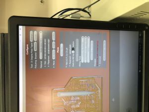
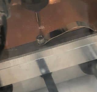
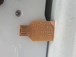
First i needed to mill the board before I could do anything else. After opening the Bantam software, I imported the board file from google drive. Huge thanks to Dr. Harris for designing the board file. Next I used the vacuum to clean the milling machines bead. Then back in the editor I selected the FR1 material. After adding all values related to the material I used Nitto tape on the back of the board to stick it to the bed of the miller. I held the material down for a good 45 seconds to make sure it had a solid connection with the bed of the miller. Then I added the .005 engraving bit onto the machine. Next i configured the machine by verifying and locating the tool position. This tells the machine where the bit actually is. Then i probed the material thickness. I did this by sliding the bit breaker onto the material and setting it to probe thickness under the bit breaker drop down. I actually forgot to remove the bit breaker on my first mill so i accidentally started the mill and managed to stop it right before the bit breaker was milled. Now, With the bit breaker removed I started the milling process. The milling process went smoothly and once it finished engraving i swapped the bits from the .005 to the 1/32 inch bit and continued the milling process. Again no issues came up and when it finished I vacuumed and removed the freshly milled board. Here are some pictures of the milling process.
Step Two: Soldering the Board:
After the board was milled I then needed to solder the components on it. Again huge thanks to Dr. Harris as he made a parts list and a schematic depicting how to solder the components. Thanks to all the time i have now spent surface mount soldering I was able to do this quickly and effectively as it only took around 20 minutes. Here are some Pictures of the soldering process.
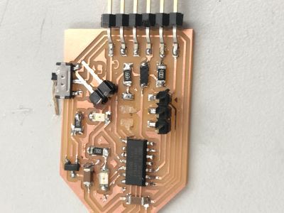

Step Three: Testing The Board:
I’m gonna be honest and say that i gave my board a 2 out of 5 chance to work. And some how it actually worked. One of the i structures showed me how to make it a programmer using a Atmil Ice and a specific set of code. I was able to get photos and videos of it blinking the onboard LED and programming the LED for the At-Tiny board. However this is where things go downhill. And i mean downhill. Because the teacher was showing me how to program the board i could not get a screenshot of the code running in the cmd. As i was walking over to my computer to get the last screenshot i needed i dropped the board and ripped the trace.
Step Four: Milling the Board Again:
Now that i broke the board i needed to mill another one. However to save time i milled 4 at once Instead of just one. However this time I altered the trace clearance settings to give the traces more room between each other. The milling process itself was identical to when i first milled the boards.
Step Five: Soldering the Boards Again:
Soldering the boards was an issue as because of the new trace clearance the traces were a lot thinner. This caused 3 of the 4 boards to break when cleaning them and the fourth one to break when soldering the chip on.
Step 6: Milling again:
This time i milled the board with the original settings and the board came out much better. Milling was identical to the first step and no complications arose.
Step 7: Soldering and testing the board again:
Soldering was easy and without struggles and when it came time to plug it in it actually worked. And i was able to get the last screenshot that I needed.
Thoughts:
Although this was the Bain of my existence for the past week, It was not as hard as it was frustrating. In the end I was happy with the final result and learned just how fragile traces actually are.
How I Tested The Board:
First to make the board readable via usb by the computer I needed to connect it to my computer Via USB and an Atmil-ICE. Then i downloaded 3 files which are all listed on Dr.Harris’s Site along with an in depth guide on how to program your board. Here is a Link To His Site.
Next i needed to open the windows CMD and cd over to my desktop because that is where i had saved the three files. With the CMD now set up correctly i would run this command.
edbg-windows-r24.exe -bpv -e -t samd11 -f sam_ba_Generic_D11C14A_SAMD11C14A.bin
Then I got a screen that looked a bit like this.
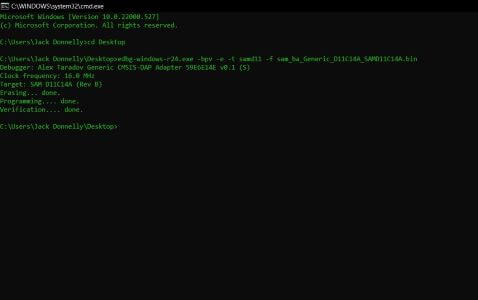
This means that the board has been programed to communicate with my computer via the built in usb. Next i tested to see if it worked with a program to blink the onboard LED light.
Here is A Photo of the code and the chip blinking.

Here are the SAMD11C programmerfile.
Group Project:
The Last Assignment for this week was a group project. As a group we needed to make a workflow depicting how we milled these boards on out other mill bantam machines. Additionally we needed to mill a test board and see how specific settings effect the outcome. Here is a Link to the group site.