7. Electronics design:
This Week I needed to Design, mill, and test a echo AtTiny Board.
Making The Schematic:
Before I could do anything else, I needed to make the schematic for my board. I started by adding the main microcontroller AKA the AtTiny 412 Board. After that I added a 3 pin horizontal header as this was (in my opinion) the next most important thing. Then I wired the UDPI, VCC, and Ground pins together. I made the VCC pin the center header so if i were to put them on backwards I would not fry my board. Next I added a LED, Momentary push button, 330 and 4.99k ohm resistor, and a 1uf Capacitor. Then I wired everything up in a way that the button would not act as a kill switch. Next i needed to tell KiCad to ignore looking for a power supply. I did this by adding VCC and Ground Stoppers on the VCC and Ground pins of the microcontroller. Additionally I set all the unused legs on the AtTiny to disconnected so the miller would know to disconnect the unused legs from the rest of the traces. After that I reviewed everything one last time and took it to the PCB editor. Here is a photo of what my schematic looks like.

Making The PCB:
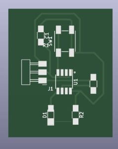
With the board now in the PCB editor, I needed to organize it in a way that no traces would have to cross. I’m gonna say this now, This is a lot harder then it seems. It was like a puzzle in a way. I would spend 10 minutes moving things around and drawing traces thinking it would work. To get to the last trace and realize it wont work. Other that that i just needed to set the trace width to .5 so they would come out nice. Eventually i got it to work and it came out looking something like this.

Milling the Board:
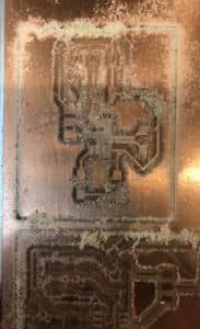
Milling was the same as it has alaways been. I would export my PCB from KiCad as a gerber and mill it on the other mills as always. If you would like to know more about the milling process check out my Electronics Production Week.
Soldering The Board:
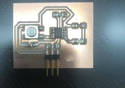
Soldering the board was not difficult as I can surface mount solder quickly now. It only took me 10 minutes to solder and there were no issues that came up.
Testing the Board:
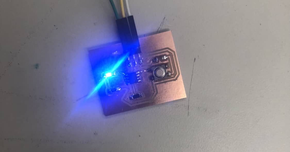
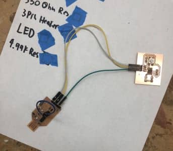
To test the board I hooked it up to my programmer and upon trying to upload the code I got an error. After a quick google search I realized that the error was happening because there was no signal actually getting to the AtTiny. I knew immediately that the issue was because of the 4.99k resistor. This was happening because there was already a 4.99k resistor on the programmer so there was no power actually getting to the AtTiny. I solved this by replacing the 4.99k resistor on the AtTiny with a 0 ohm jumper and it worked. With the test code working i was able to use the pull up and pull down resistors in the AtTiny. Here are some pictures showing how it works.
Here is the code I used for the Pull Up Resistor
void setup() {

  pinMode(2, INPUT_PULLUP);
  pinMode(3, OUTPUT); // I had to set my button as an output since I had done by button wrong


  }

void loop() {
if(digitalRead(2)== HIGH){
  digitalWrite(3, LOW);
  }
else{
  digitalWrite(3,HIGH);
  }
 }
Group Project:
For our group project we needed to learn how a oscilloscope and a multi meter measure electronic currents. Here is a link to the group documentation.
What I Learned:
So this week I learned how to design a pcb and use the schematic to solder components on in the correct orientation. Additionally I learned how to tell which pins do what on the AtTiny Board as I wasent able to orientate it using the divot. Overall I thought the process was realy cool and it felt goot tp be able to make a board from scratch.
Here you can download my Pcb Files.