11. Input devices
This week our assignemnt was to crete an input that would (if possible) be used in some way for your final project.
Chosing what to do:
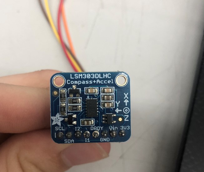
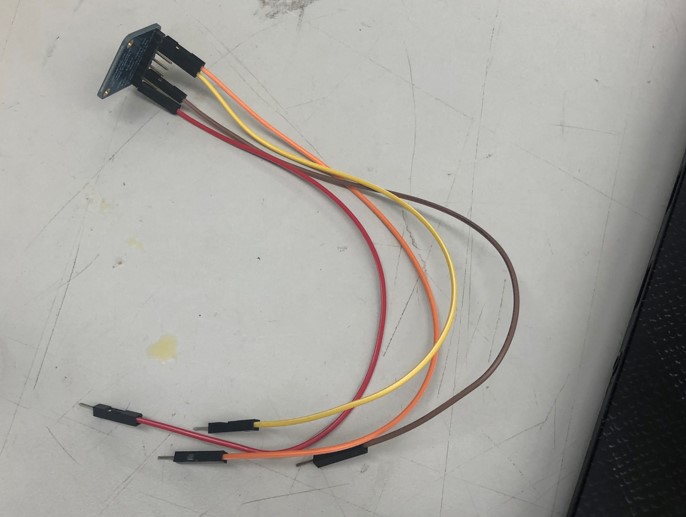
I started by breaking down all the inputs that would need to be present in my final projct. There would need to be a transmitter, altimiter, position holder, spedomitor, ect… After a bit of searching in the lab I found a LSM303DLHC accelemoter sensor. The way it worked was by logging its x, y, and z posiitons based on where it was powered on. With this method of logging I was able to take care of 3 of my inputs, the spedomitor, altimiter, and position hold feature. The sensor would be running of a typical 3.3v power supply, an SDA, and SCL pins for reading and writing via the serial monitor. Here are some photos of the sensor I am using.
Now that I had my sensor all wired up, i connected it to an Arduino using this photo on adifruits page as a reference. Because this was an adifruit sensor, it was explained in great detain on how to use it, set it up, and what it does. Here is a Link to the product page. It is important to note that the exact model of the sensor I was using was outdated and discontinued so I was using a guide for a more modern version and altering it as I went. Here are some photos of the Guide I was using.

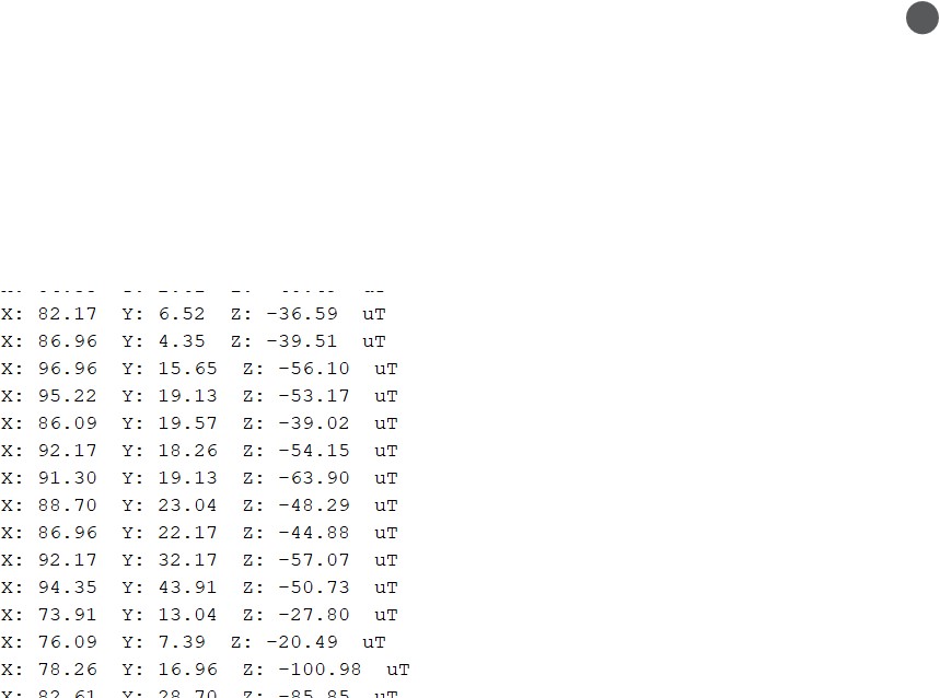
After downloading the LSM303DLHC library’s along with its dependencies which were all listed on Adifruit, I wired the sensor up to an Arduino and ran the example code. Then i opened a 11500 baud serial monitor, and to my surprise it actually worked first try. Here is a photo of what the sensor was printing out on the serial monitor.
Here is the Code I used
#include <Adafruit_LSM303_Accel.h>
#include <Adafruit_Sensor.h>
#include <Wire.h>

/* Assign a unique ID to this sensor at the same time */
Adafruit_LSM303_Accel_Unified accel = Adafruit_LSM303_Accel_Unified(54321);

void displaySensorDetails(void) {
  sensor_t sensor;
  accel.getSensor(&sensor);
  Serial.println("------------------------------------");
  Serial.print("Sensor:       ");
  Serial.println(sensor.name);
  Serial.print("Driver Ver:   ");
  Serial.println(sensor.version);
  Serial.print("Unique ID:    ");
  Serial.println(sensor.sensor_id);
  Serial.print("Max Value:    ");
  Serial.print(sensor.max_value);
  Serial.println(" m/s^2");
  Serial.print("Min Value:    ");
  Serial.print(sensor.min_value);
  Serial.println(" m/s^2");
  Serial.print("Resolution:   ");
  Serial.print(sensor.resolution);
  Serial.println(" m/s^2");
  Serial.println("------------------------------------");
  Serial.println("");
  delay(500);
}

void setup(void) {
#ifndef ESP8266
  while (!Serial)
    ; // will pause Zero, Leonardo, etc until serial console opens
#endif
  Serial.begin(9600);
  Serial.println("Accelerometer Test");
  Serial.println("");

  /* Initialise the sensor */
  if (!accel.begin()) {
    /* There was a problem detecting the ADXL345 ... check your connections */
    Serial.println("Ooops, no LSM303 detected ... Check your wiring!");
    while (1)
      ;
  }

  /* Display some basic information on this sensor */
  displaySensorDetails();

  accel.setRange(LSM303_RANGE_4G);
  Serial.print("Range set to: ");
  lsm303_accel_range_t new_range = accel.getRange();
  switch (new_range) {
  case LSM303_RANGE_2G:
    Serial.println("+- 2G");
    break;
  case LSM303_RANGE_4G:
    Serial.println("+- 4G");
    break;
  case LSM303_RANGE_8G:
    Serial.println("+- 8G");
    break;
  case LSM303_RANGE_16G:
    Serial.println("+- 16G");
    break;
  }

  accel.setMode(LSM303_MODE_NORMAL);
  Serial.print("Mode set to: ");
  lsm303_accel_mode_t new_mode = accel.getMode();
  switch (new_mode) {
  case LSM303_MODE_NORMAL:
    Serial.println("Normal");
    break;
  case LSM303_MODE_LOW_POWER:
    Serial.println("Low Power");
    break;
  case LSM303_MODE_HIGH_RESOLUTION:
    Serial.println("High Resolution");
    break;
  }
}

void loop(void) {
  /* Get a new sensor event */
  sensors_event_t event;
  accel.getEvent(&event);

  /* Display the results (acceleration is measured in m/s^2) */
  Serial.print("X: ");
  Serial.print(event.acceleration.x);
  Serial.print("  ");
  Serial.print("Y: ");
  Serial.print(event.acceleration.y);
  Serial.print("  ");
  Serial.print("Z: ");
  Serial.print(event.acceleration.z);
  Serial.print("  ");
  Serial.println("m/s^2");

  /* Delay before the next sample */
  delay(500);
}
To my luck, the only thing I would need to change on the code would be the Baud Rate of the serial monitor because the only pins that were being used were the SCL and SDA pins.
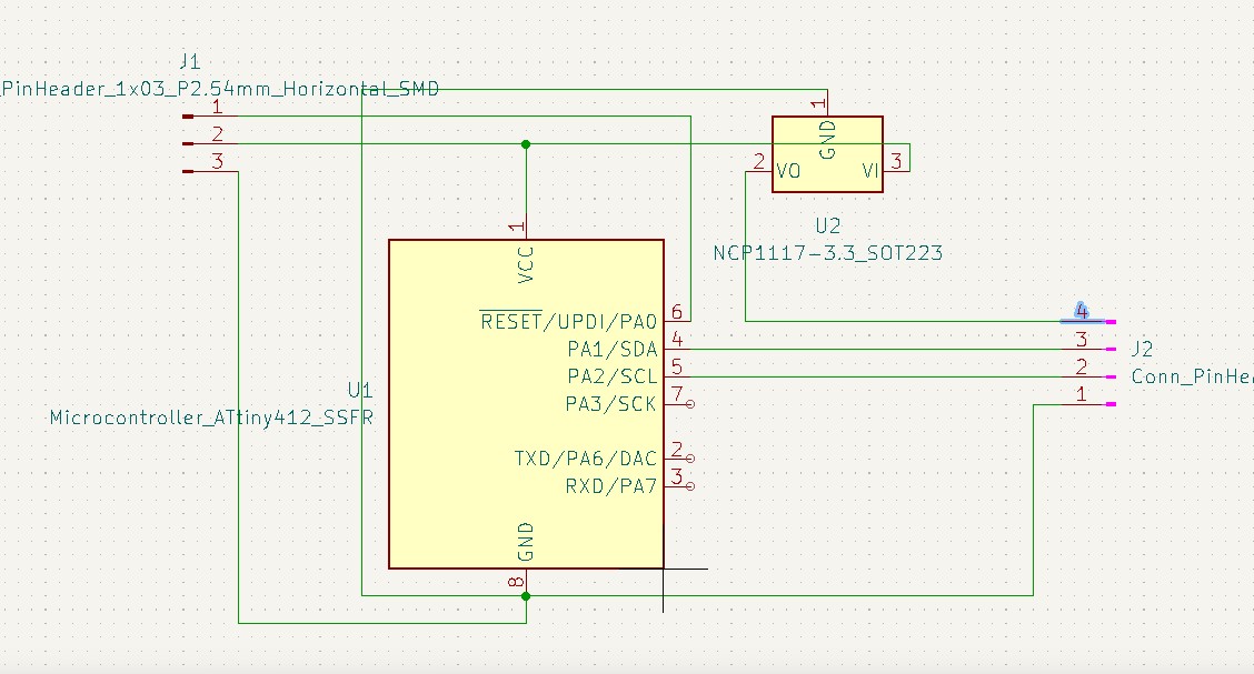
Now that I had my Arduino circuit up and running I was able to begin creating a schematic. This was reletivly easy as I just referenced the Arduino circuit I had connected beside me to create the schematic. However, unlike output week, I actually made sure everything was connected to a ground…. (I lost to much sleep on that week). After around 30 minutes I had a schematic that looked like this.
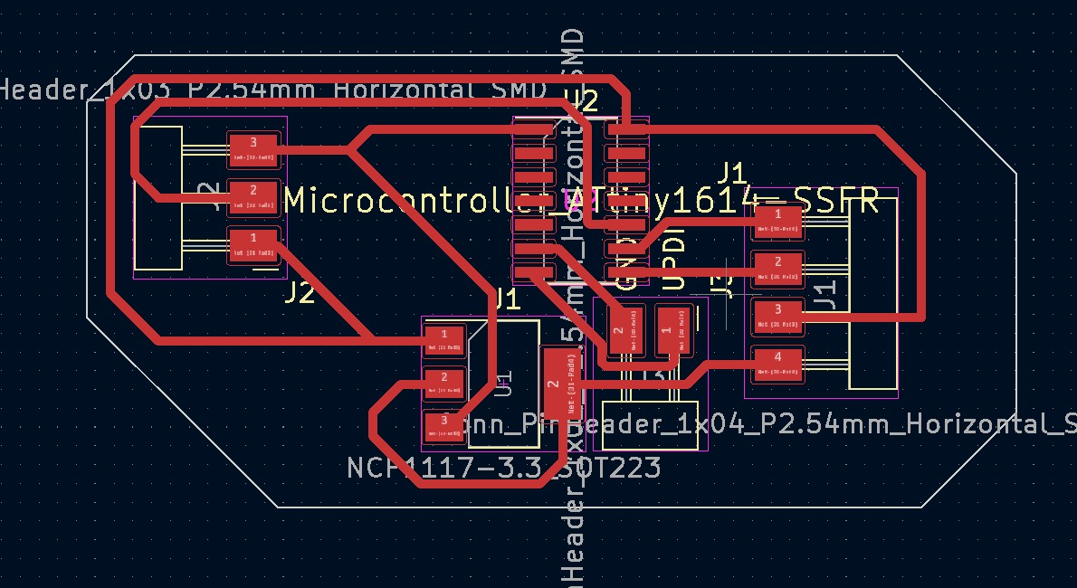
With the Schematic set up, I imported it into the PCB editor and began creating The PCB. I have actually gotten very experienced with this and needed to use no zero ohm resistors. After around 3 try’s in the editor and i bit of adjusting the grid snapping, I had a PCB that looked like this.

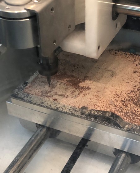
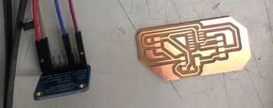
Now that I had the PCB created I exported It as a gerber file and sent it to the Othermill. I milled the PCB using a 1/32 bit for the majority of the mill and the 0.005 for the fine details. Milling has become very easy for me and If you would like to learn more about my milling process please visit my electronics production week. Here are some images of the Milling process.
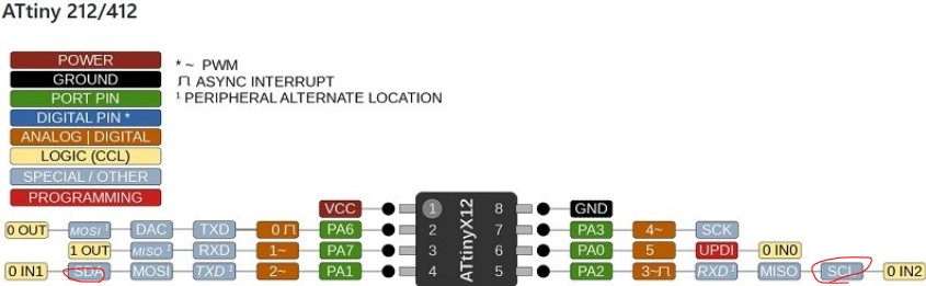
Once the mill was complete, I began soldering the components on. These components were made up of 1 AtTiny 412, a 2 pin vertical header for the RX and TX pins. A 3 pin header for UDPI, Power, and ground, a 4 pin header connecting to the sensor, and a 3.3v regulator to prevent the sensor from exploding. The soldering process was not hard and after a bit of time, I had this.
I proceded to wire everything up and after consulting the 412 pinout sheets. And once i hooked it up to my computer I got this error stating “Failed to compile for chip AtTiny 412.” After a bit of research and talking with Dr. Harris, I figured out that the hardware in the attiny 412 was not sufficient to read the library’s data. After a bit of googling and thousands of results for AtTiny 85s, I learned that the library’s were compatible with the AtTiny 1641 chip which we had in stock at the lab. With a quick edit to my schematic and PCB i ended up with something looking like This.

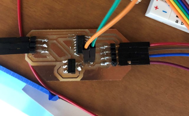
Next I milled and soldered the New PCB using the same materials as before with the exception of replacing the 412 chip with a 1614 chip due to the library compatibility issue. Heres a photo of what the finished product looked like.
I wired the sensor to the board the same way I had before and then plugged it in. I uploaded the code. It was a bit funny at first because It was printing to the serial moniter but it was comming through in random characters insted of the correct format. I knew immideatly what was wrong and after fixing the Baud rate, It worked!!
Takeaways:
Overall I learned alot about TX and RX pins and how serial moniters work. I had fun working on this week and I also learned how important it is to check hardware compatibility before starting anything.
Link To Group Site:
Comming ASAP