10. Molding and casting
This week our assignment was to design an object of our choice, turn it into a mold, CAM, and mill the mod on the othermills, and then mold and cast our object.
Chosing what to make:
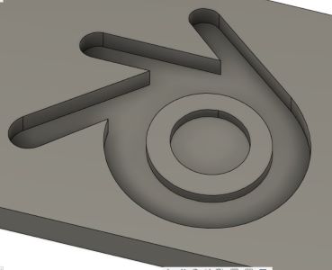
First I had to pick what I wanted to make. Being a part of Team Blender, I decided to mold the blender logo. I decided to design it in fusion (I Know Its Hypocritical) because it was a simple design and fusion would be easy as I would not have to import an STL. Designing the logo took around 20 minuites as i just imported a refrence image and traced it using 3 point splines. After the logo was designed I was ready to CAM it. Here is a photo of the finished CAM:
Camming My Design:
With the Blender logo Finished It was time to begin the CAMing process. CAM stands for Computer-Aided Manufacturing so it was only reasonable that this would be done under the manufacturing tab in Fusion360. Once imported into the manufacturing tab, I needed to make a setup. In the setup window I needed to configure things like the position, origin, stock, and type of machine. I set the machine to a standered xyz miller. It was the autodesk fusion 360 standered. Next i set the x, z, any y axis in the correct orientation. The be beds run on the Y axis while the bit moves left and right on the x axis and up and down on the z axis. Next i needed to set the origin. According to the bantam website, the origin needed t be set to the top left corner of the model. Here is a photo of the design in the manufacturing tab and the setup window:


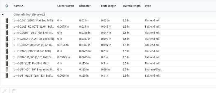
Before i could continue I needed to import the bantam tools library. This would allow me to set specfic bits that we currently had in the lab. This way I could accuratly simulate the milling process. Adding the Library was easy as it was as simple as clicking import tool library under the preferences menue. Here is a image of the tools included in the Library.
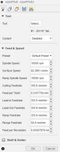
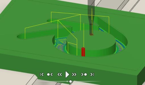
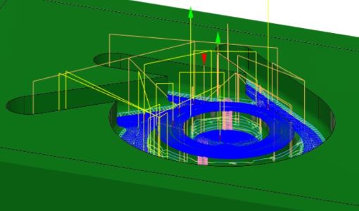
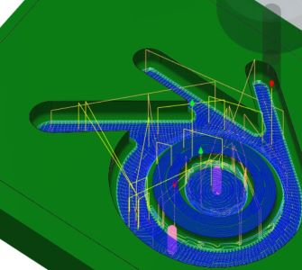
After I finished the setup portion of the CAMing process I needed to add the toolpaths. In total I needed to have 2 toolpaths made. The first one would be a 3D adaptive Clearing toolpath that would act as the roughing pass. The second toolpath would be a 3d Horozontal that would act as the finishing cut. Addidionally I decided to use a 1/16 flat endmill for the roughing bit, and a 1/8 ball endmill for the finishing pass. Basically the flat end mill would take out the bulk of the material, while the ball end mill would take out the creases and rough patches made by the roughing pass. To begin I first added the adaptive toolpath. This was very similar to the setup as the options were very similar. All I needed to do was select the 1/16 flat endmill and then uncheck 2 checkboxes. Then i hit ok and it caluculated the toolpath. I then simuilated it to make sure there were no visible errors. With the exception of the simulation almost bluescreening my laptop there were no errors. Next I needed to set the toolpath for the finishing pass. This was the exact same as the adaptave cut except I chose the 1/8 ball bit insted of the 1/16 flat endmill bit. The hardest part of this whole process was analizing what errors would not ruin anything. There was one collision error where the stock was colliding with a part of the model but after re-watching the simulation a couple hundred times a decided to take the risk and if i ruined the was block i can always try again! (Turns out my gess was correct as you will see later.) Here are some images of the toolpaths and the setup menue for the toolpaths.
Exporting Toolpaths And Milling:
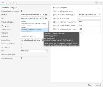
With the toolpaths approapitly configured and no visible errors I was ready to export from Fusion360 to Bantam tools. In orded to export my file as GCODE I needed to do something called post-processing. I set the machine to the Othermill and thats really all I needed to do.
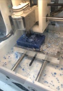
Next I opened the toolpaths in the bantam software and began setting everything up. I set a 1/16 flat end bit for the roughing cut and a 1/8 ball bit for the finishing pass. I also set a generic material and made it the same size as the wax block I was using. I then Located the bit and taped the Wax block onto the machine Bed. The other process of changing the bit was the exact same as before. If you would like to learn more about how I mill on the othermills please refer to my Electronics Production Documentation. Here are some images of the milling process:


Casting My Design:
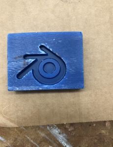
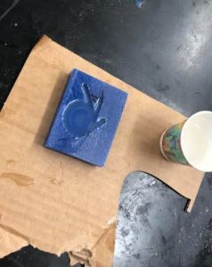
With the design milled out I was ready to begin casting. Because I had no real use for this mold i decided to use dragonskin resin. The only reason being because it sounds cool. After grabbing some gloved and my materials I started by spraying easy release into the mold. This makes it easy to remove the cast from the mold once it has fully cured. Next I began reviewing the https://www.smooth-on.com/tb/files/DRAGON_SKIN_SERIES_TB.pdf for the dragon skin mold to make sure i was not doing anything wrong. The majority of the information was on page one of the datasheet. I began preparing the mixture. Dragon skin was a one to one ratio so i put the same amount of each in seperate cups. Then i poured the cups into one and mixed for around a minuite. Then I poured the mixture into the mold and let it set. Here are some photos of the Casting Process:

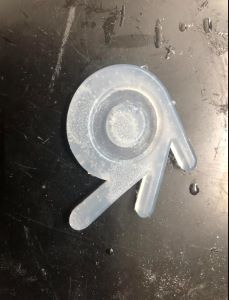
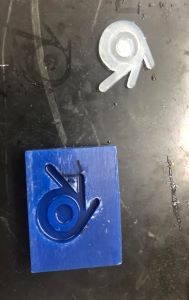
After Letting the mold sit and cure overnight it was ready to be removed. I used some needel nose tweesers to get under the cast and with one pry it was released. Upon analizing the mold i relized that there were a few tacky spots. This was because I did not mix substance A and Substance B together well enough before I poured them into the Mold. Also i relized that because i did not mirror the mold, the logo came out reversed. Im not quite sure how I managed to overlook That. Here are some images of the Final Mold.
Learnings:
So I thought this week was interesting and fun but with the applical side to using this in my final and future projects, im not sure i will do this again. I did get to learn how to cam and fusion and am sure i will use that feature often in the near future.
Group Site
Here is the link to our group site for this week. Nick and I worked on experimenting with different types of resins. I did the more rubbery and flexible resins while Nick did the harder and more rigid resins.
Files:
Here you can download my GCODE Logo Files