3. Computer Controlled Cutting:
Assignment 1: Computer Controled Cutting:
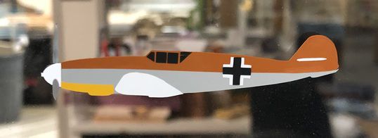
The first task for assignment 1 was to cut out a multi layered/colored vynal sticker that would be put up on the wall. I decided to make one of the most iconic fighters from World War II, The Meshershmit BF-109. The software I used was Corell draw as it has some key features that will make this alot easier.
First I scowered the web for a good refrence image that I would use to create the basis for the sticker. I found several images that I tried to trace using Corell’s Bitmap trace function but nothing came out good. After about 30 minuites of trial and error with different images I decided it would just be quicker to manually trace it. I started out by tracing the silloute of the airplane which would act as the base for the other colors. Also thanks to a fellow fab academy Aaron Logan who gave me the idea to put a star in the same position on every layer. This would make it easier for me to line up the layers accordingly. Here is a link to his site. After finishing the silloute of the body i would duplicate it and edit the duplicate to look like a specfic section that would be a diffrent colors. The main sections i had were the propeller, the nose, yellow paint on bottom of nose, wings, roundel, top tan paint, bottom grey pant, and canopy. everything was going well untill I attempted to export the files from corell to siloutte. for some reason everything lost its scale and each section was out of porportion.this wasent to hard to fix it just took a really long time. I had to copy and paste a resized version of the fuesalage onto each skech and manually resze them. Aarons trick with the star really helped so big shoutout to him. After everything was resized I was able to begin cutting them out which went smoothly with no issues. Then i put each layer on the wall starting from bottom to top. I think the end result came out looking good.
The Second task for this assignment was a group project where we had to find how Power, Speed, Focous, and Frequency alter the final result of the laser cut. here is a link to the Group_Site which contains more information and the perspectives of other groups. Additionally we needed to find the kerf and joint clearece. As a whole group we needed to test thest things on all 3 types of lasers that are in the lab. Each laser was a diffrent wattage with the smallest being 30 watts, the middle being 50.. watts, and the largest being 125 watts. There were 4 overall groups so we had 2 of the groups use the big laser and find everything on plywood and cardboard, while the other 2 groups ran the same tests on the other 2 lasers but only used cardboard. I was in the group that tested the 2 smaller lasers. How we woud find the power, speed, focous, and frequency was self explanitory as we would just run test with each run being at increments of 10 %. For example if we were testing power, speed, focous, and frequency would be set to the normal values while power would increase by 10% for every test. It was a similar setup with the speed and frqency aswell. Here are the results of finding speed, power, and frequency.

Here is a folder contaning all the files I created for the sticker:
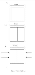
Next we needed to find kerf. I made a sketch/guide on how I thought we should do it. First we would cut a 3 inch by 3 inch square and then mesure it. Then we would take calipers and measure the width of the square. we would use the ruler attached to the calipars to make sure it was lined up perfectly. Once we got the mesurment of the width, we would mark the side of the square perpindicular to the side we mesured. If we were using plywood we could find kerf this way but since we were using cardboard the calipers woud sink into the divits on the side making the measurments inaccurate. Then we would put the square back into the laser cutter with the marked side facing the top of the laser cutter. Then we would cut a line down the middle of the suqare. Both sides of the square would then be pushed together and we would re mesure the new width of the square. then we would subtract new width from old width and that would be our kerf. Here are some photos of the kerf tests and the final cuts of speed power and freq tests.

Here is a photo of my Ultmate Guide to Finding Kerf:
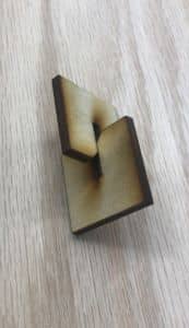
Lastly for the group project we needed to experiment with joint clearence. Neil gave us a picture depicting several joint shapes and we picked 2 of them to try. Here are photos of what both joint types looked like.
We chose plywood for our cutting material as cardboard would bend under a bit of pressure making it a bad material to test on. We had to cut a total of 7 joints before we found a width that allowed the joints to fit together sungly while not being to tight. the first 4 were to lose while the 5th and 6th ones were to tight. The seventh one fit just right as it wasent to lose or tight. The first style joint does allow fior stronger connections but the second type is much easier to assemble due to the angle it has. Here are some images showing the failed tests along with the final working joint.


Press Push Kit
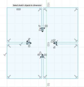
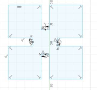
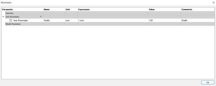
The final part of this this weeks assignment was to use parametric design to make an assortment of cardboard peices that would fit together like legos. By using paramaters I would be able to change the width of the slits to fit a diffrent material. for example if i needed to cut on a thicker material i could change the value of te paramater from the tickkness of cardboard to the thickness of this new material. Paramaters are incredibly helpful as thel allow me to alter all slits by changing one value insted of changing each one individually. The creation of the shape wasent to difficult as it just involved creating a square with slits on each 4 sides. From here on out it was the exact same thing as joint clearence as cutting them out was very similar due to using the same material and lazer. Here are some photos of the design process.
Here is the file i created: