8. Computer controlled machining
This week I needed to design and CNC something that was around a meter in size and was assembeled without using bolts and glue (Press Fit).
Chosing my design:
Recently I have gotten very into a metroidvania type game called Hollow Knight. In this game benches are used as save points so I decided to make a Hollow Knight themed bench. I started of by looking for some nice refrence images online. I ended up basing my design off the white palace bench from the game.
Planning My Design:
Now because this bench is from a fantisy metroidvania, its not exactly structually stable in the real world. To begin I sketched the top part of the bench in fusion. This part would be close to a meter long as that was the requirement for this week. Additionally I needed to make it in a way so it would require no screwes or glue to hold it together. I started out using the face of the Hollow Knight as the centerpiece of the bench. Then used vyne type lines to connect the face to the actuall part of the bench. I Ended Up With Something Like This.

I played around with it a little more and added these spires on each side to make the height a similar size as the Hollow Knights Head. It turned out looking something like this.

Next I designed the bottem of the bench. In the game a nial is the equivilant of a sword so i decided to use the Hollow Knights Nail and embbed it into the design of the bench. I designed the bottem in a very similar way as the top. I started with a outline of the size I wanted it to be, Then designed the centerpiece/Hollow Knights Nail, then added vine like patterns that not only looked cool but also were structually sound. The end result came out looking like this.

Next up were The Archs. There would be 2 types of archs that would help support the bottem of the bench. 2 of the archs would have a tab on the top that extends into the bottem while one would not have a tab and just act as a brace for the bottem. Additionally I Also designed 2 brace beams that would brace the back of the bench and keep it from bending. Both the beams and the archs were easy to design and they came out looking something like this.

After the archs were done I Started designing the legs for the bench. I went with a similar stile to the top of the bench. I mesuered the legs to be a bit shorter then my legs so it would be a decent sized bench. After designing one leg I duplicated it to make the other one. Here is what the leg came out looking like:

Test Cuts:
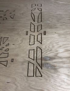
With the Files Designed I started a test cut. I had some issues sendig the dxf’s to corell draw. after a bit of research I learned that this was happening because corell could not understand splines in a dxf. So i put it through a dxf to svg converter and it worked fine. I ran the first test cut out of cardboard on the laser cutter and came across a few issues. Mostly the fact that the bench looked way to tall. Here is a photo of what the test cut looked like:

After seeing what needed to be fixed I altered the height of the legs and they now looked like this:

With the height fixed i ran another test cut and It came out looking great. All the files were the same with the exception of the new legs. Heres What it came out like:

Preparing For CNC Via Aspire:
Now that I knew all pf my files were working, I measured the thickness of the wood I was using. The Thickness came out to around 0.721 inches. I altered the paramaters controling the tabs in fusion to set them to the correct width. Then I Uploaded the altered files to aspire. In aspire I would add the Dogbne fillets on the tabs and create the toolpaths. I set the material Thickness to 0.721, disabled the offset, and instructued it to zero on the bed of the machine insted of the material. This is important as the material is not consistant so a zero off the material would not be accurate. Here is a photo of what the top of the bench looked like in Aspire:
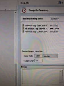
With the material settings updated and all the files added and positioned I could begin adding dogbone fillits and tabs. To my supprise this was reletivly as I just clicked on the add dogbone button, and then clicked where I wanted to add them. Then I needed to add the toolpaths. I had the option to chose if the bit would mill on the inside, outside, or on the line. For the interior cuts I had it cut the inside but for exterior cuts I had it cut the outside. I needed to do this because this would keep the tabs the appropiate size without making them to big or to small. Additionally I needed to add tabs to the toolpaths. Tabs would prevent a peice from being lifted up and flung around the room when it was fully cut. I would need to chissel the tabs when it was finished but its better then destroing the entire cut in the process of cutting it. Lastely I needed to add a toolpath that would mark where I needed to drill the board in. This was so the board would be really secure while it was cutting. Here is a photo of the first 3 Toolpaths:

Preparing The ShopBot
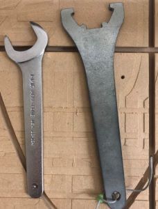
This is actually the first time I have done anything with woodworking with the exception of small things on the laser cutter so I was a bit nervious going into this as I have never used the Shopbot before. Before I did anything I needed to warm up the spyndle so it wouldnt break when it started spinning. This process was easy and it only took 10 minuites to warm up. Next I needed to insert the bit I wanted to use. I decided to use 1/4 inch Upsprial Bit. I chose this because I Had these small peices that I would need to be pulled up and not pushed down. Additioally I did not want the wood to warp due to sawdust becoming trapped under it. Here are some photos showing how I changed the drilling bit.
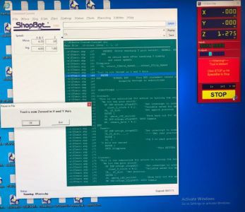
With the bit prepared and the shop bot warmed up i net needed to set its home position and calibrate its z axis. First, under the Zero tab on the shopbot application i clicked on zero X, Y. This caused the shopbot to move to the bottem left corner. Next i typed Z2 in the command line. This Set the Shopbots current position as its origin. To make sure the origin was correctly set i typed j2, 0, 0 in the command line and the shopbot did not move. This showed me that the origin was correctly set. Here is a photo of the shopbot at its origin and the shopbot application:

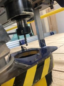
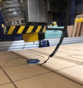
Next I needed to zero the Z axis. As I mentioned before the Z axis needed to be zeroed off the machine bed and not the material. This is because the material is not consistant. To zero the Z axis i needed to position a metal plate connected to the shopbot below the spindle of the machine. Here are some photos of the plate that I used to calibrate the Z axis:

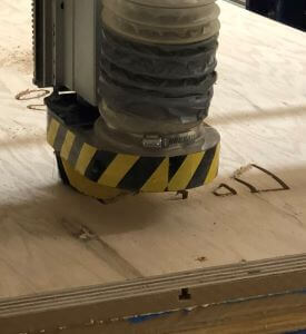
To actually start the calibration process I went into the Shopbot Application and under the zero menu, selected Zero Z Axis. The Spindle then slowly went down towards the plate on the machine bed. When it made contact with the plate it paused for a second and then procedded to rize around 1.25 inches above the plate. Here is a picture of the Spindle touching the plate:

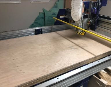
Now that the shopbot was zeroed on all 3 of its axies, I needed to mount the wooden sheet. I lined up the corners of the wood with the edeges of the machine bed and then bolted it in with a few screws along the edeges. Here is A photo of the board on the Machine Bed:
Cutting The Bench:
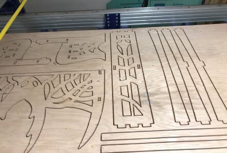
Now that the Board was secured into place on the machine cut I could begin the Drill Marking Cut. This cut would put a small divot in the wood. The divits were markings of where I would need to screw the Board into the machine bed. However, Before I could actually cut, I needed to run an air cut to make sure everything was working properly. An air cut is when the machine acts like its cutting but never actually touches the board. I can perform an air cut by setting a 3d offset to a toolpath before it runs. With My toolpath imported and ready to aircut, I needed to start the drill bit. I did this by pressing the green button on the panel next to where i was standing. Once the spindle was spinning I could start the air cut. Here is a photo of the Air Cut and the Panel:


The Aircut finnished with no issues and now I was ready to actually cut. This process was the exact same as the aircut, However i did not set an offset in the options menue. Here are some photos of the cut running.

After around 2 and a half hours my cut was finished and I was ready to begin assembely.
Assembeling The Bench:
The Asembely of the bench was not all that hard but it was time consuming. First i propped the wood up against a wall and began chissiling each peice out of the wood. After everything was removed i began sanding each peice with a handheald rotery sander to make the edeges smoother and prevent splinters. After all of the sanding was done I could begin assembeling the bench itself. Here are some photos of the process:


When I tried to slide the back of the bench on I relized that I overlooked one key factor. Plywood does not bend when its almost an inch thick. My designe had been designed with the intent that i would slightly bend the back i order to slot it into the bench itself. This was no problem with the test cuts as they were made out of thin materials, however it was not possible to do with the plywood. I got around this by sawing off the 2 tabs that woult help secure. Turnes out, they were not needed anyways.

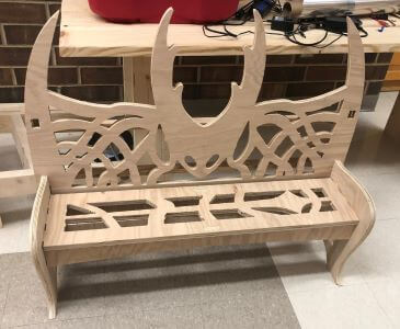
After I got around that the final result came out looking good, albeit a bit small, but nonetheless still meeting the requierments and using no screws or glue.


Takeaways:
Throught the corse of this week I learned how to cnc using the shopbot and aspire and how to designe something that not only looks cool but is also stable. I learned to take into account what material am using and more then just its strenghts and limitations but what it can do. Woodworking is fun for the mostpart, however I dont see myself using it all that much for my final project as I am not using balsa and something of shopbot scale it was to big for my project.
Files:
You can download my Hollow Knight Bench Files here.
Group Work:
Here is the Group Site Like where we documented the characteristics of the shopbot. I documented different ways to fixture the materials onto the bed of the shopbot.