10. Molding and casting
Group Project here.
Download pass 1 file here and pass 2 here.
Designing the Cast
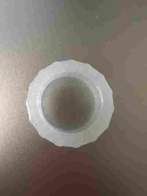
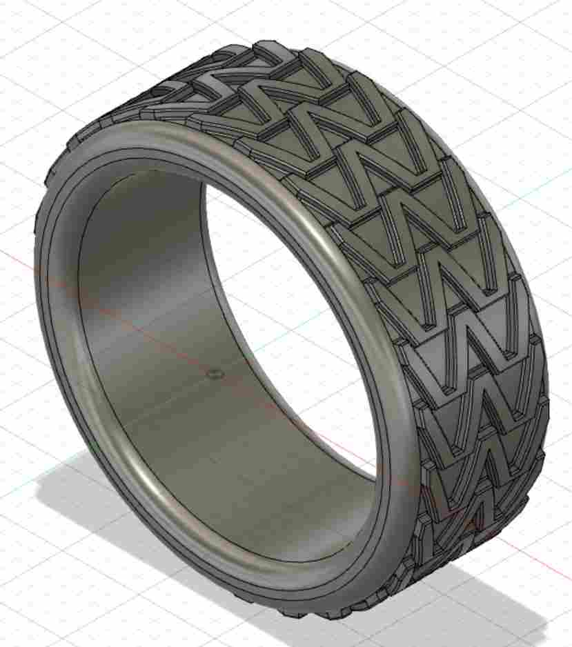
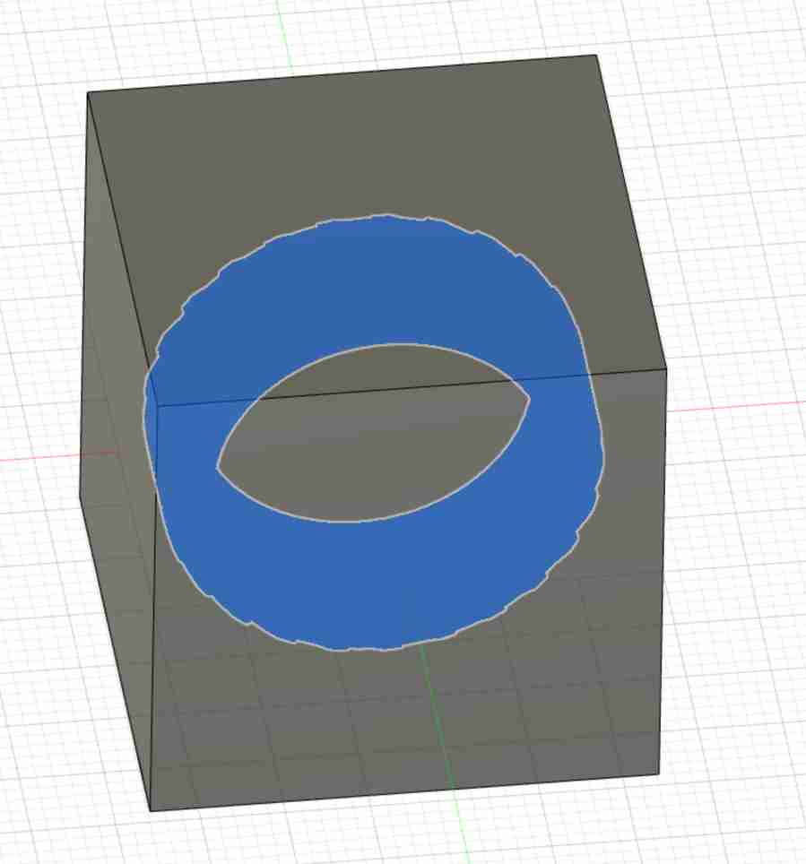
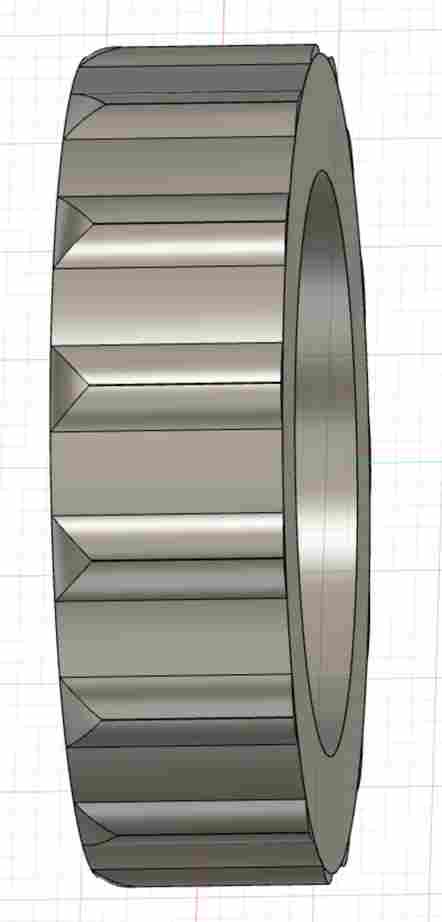
It took me awhile to decide on what to mold. I really wanted to do something for my final project but many of my parts will need multiple iterations and “molding” and “iterating” just seem like oxymorons. I decided against molding a component for my final project, but that didn’t mean I couldn’t still get a better understanding of the materials I will need for it. The material on the wheel below:
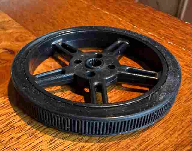
seems to move a football well when I tested it with a servo (see here for why that is applicable for my final project). The material feels like rubber but I theorize that the texture, or pattern, has a lot to do with the friction it creates with a football, too. I will need some sort of timing belt or wheel for three processes:
1) Slowly spinning the football to find the laces 2) Move the football up the to the wheels via a conveyor belt 3) Throw the football
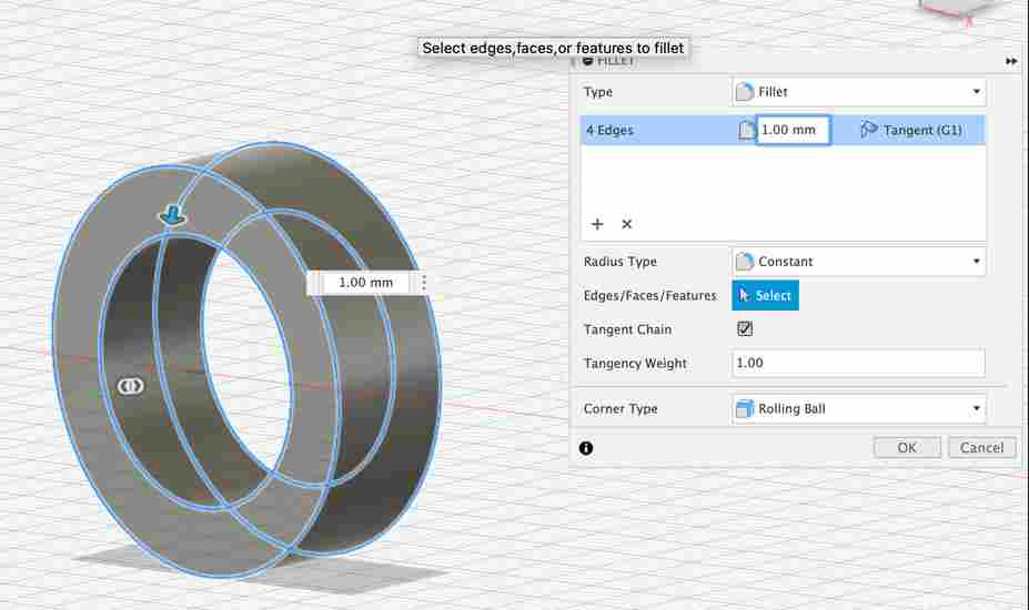
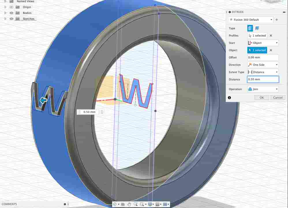
The wheels to throw the football will be quite large and will need to be very precise so I don’t think molding will be useful for that for now. However, I can ues this week to test different patterns and materials for (1) and (2). In addition, molding a tire is a good chance to learn how to extrude patterns on surfaces. So, I begin to design my tire by drawing two circles, extruding, and then adding a fillet to the edges:

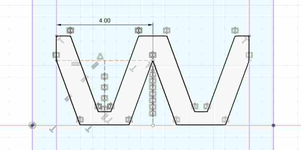
At first I wanted to test out a different pattern than the wheel I have at home (you’ll notice why I don’t in a bit) but here was my first tire track sketch and extrusion:
Like before, added a fillet to the edges:
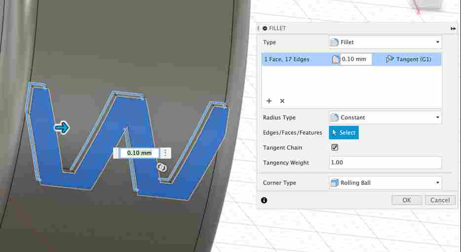
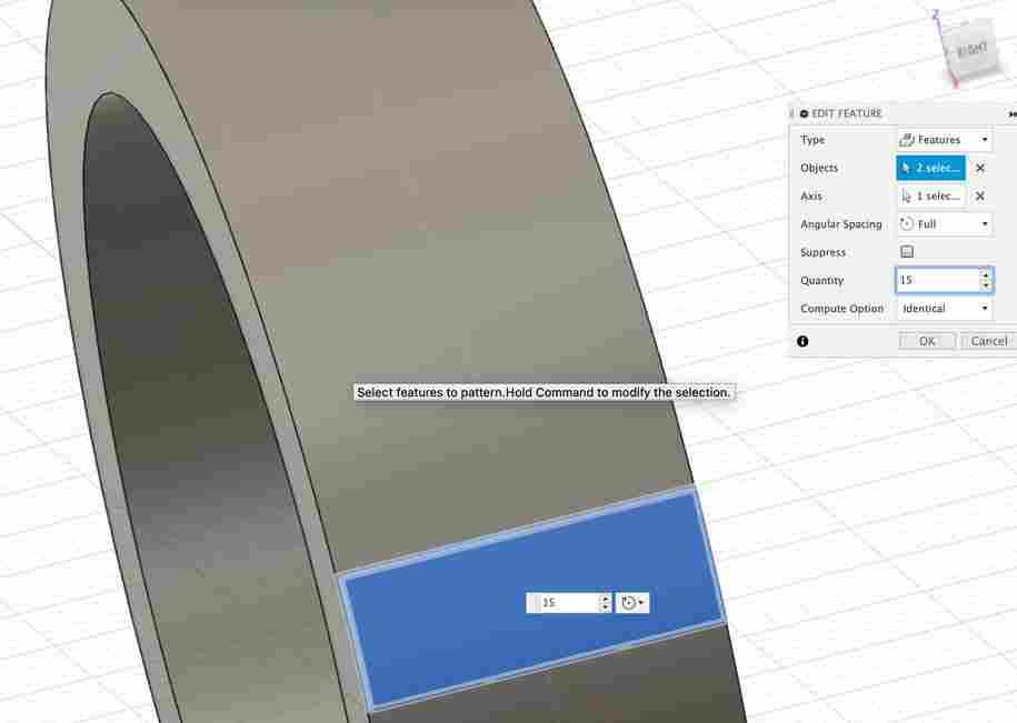
and repeated this pattern around the tire’s “profile”:
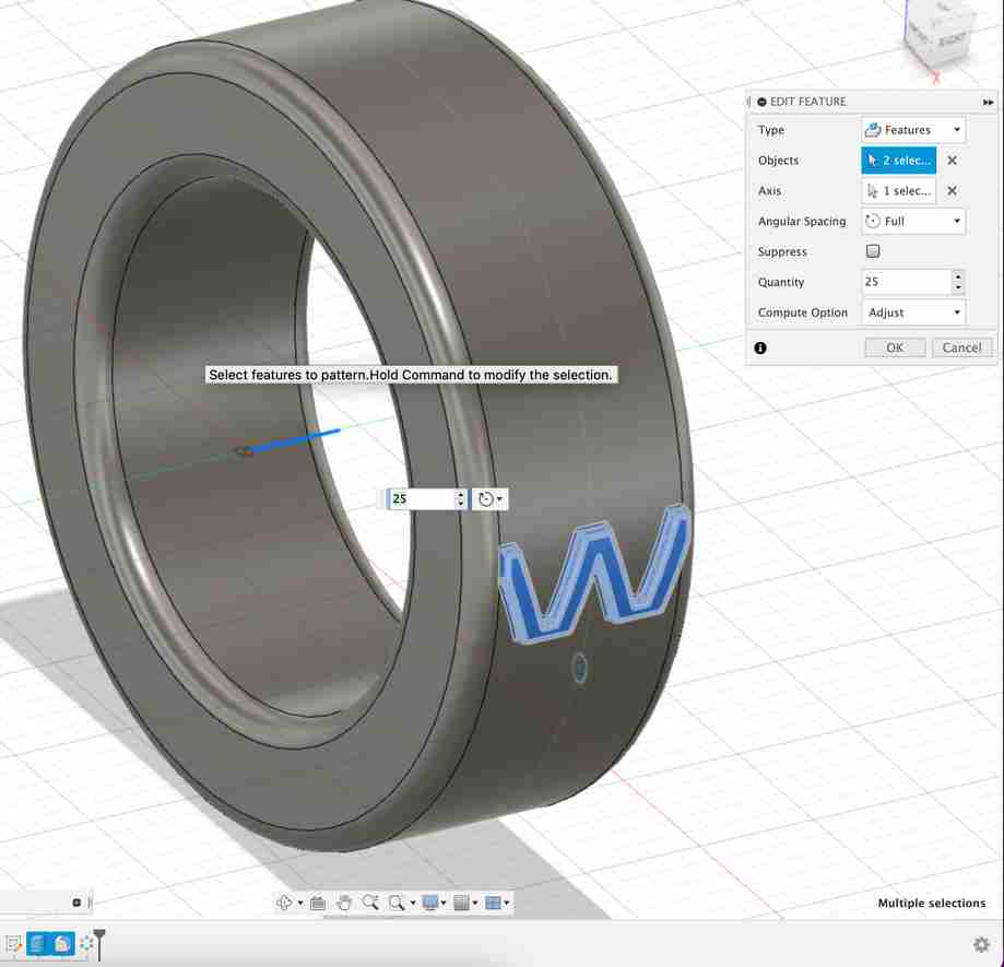
But, then I saw it…
Our Bantam mill cannot cut this design because of its the dovetail cuts I would have to ask it to do:
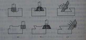
This would be easier is we had a bit that was wider at the bottom or had a mill that is more than just 3-axis (as shown in the bottom right of the picture above). In the interest of time, I decided to go with a pattern similar to the tire I have at home because I could not think of another useful design that could easily be milled.
So, I sketch a line and extruded that:
Designing the Mold
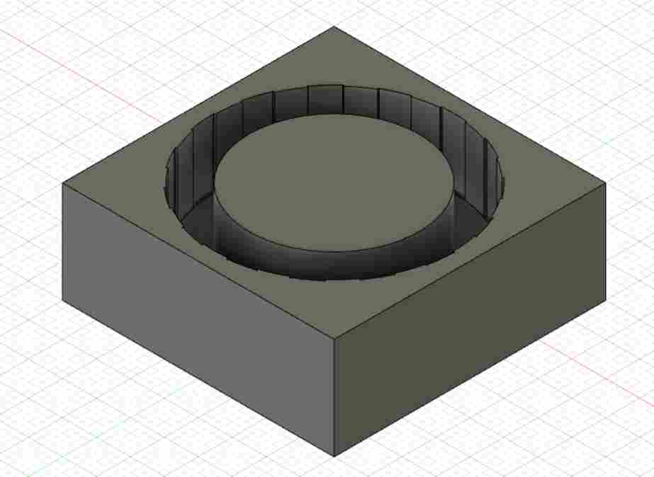
To design the mold, I first put a box around my tire, combined the two bodies, and extrude-cut the tire out of the box:
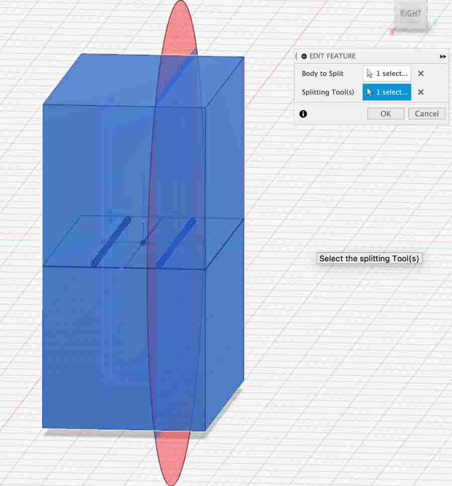
My first instinct was to put a plane directly in the middle of the box for splitting the mold. Then, I would have two identical molds. But, when I thought about the process of filling the molds with the liquid material, I wasn’t sure how I’d get the liquid in each the molds and press them together without any liquid spilling out. Instead, I put a plane near the top of the tire and split the box there:
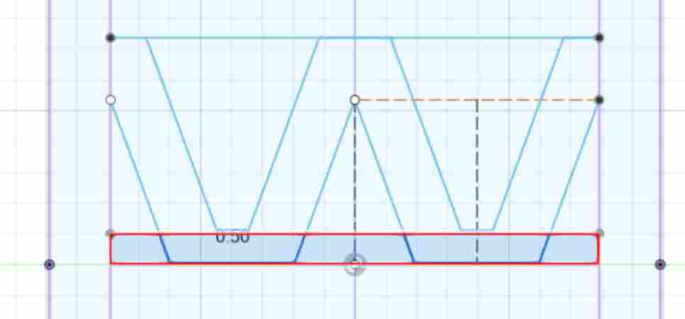
Unfortunately, I was told that my two mold design wouldn’t be successful. It would need a pouring hold and some sort of vent? I’m still not totally clear on what is necessary for a two mold design but in the interest of time I decided to just use one mold. After all, this assignment is just for getting the hang of molding and casting. So, I deleted the fillet on the edge of the tires - removing the need for two molds. In addition, I was worried that my tire tracks were too small (0.5 mm) so I decided to make those much bigger:
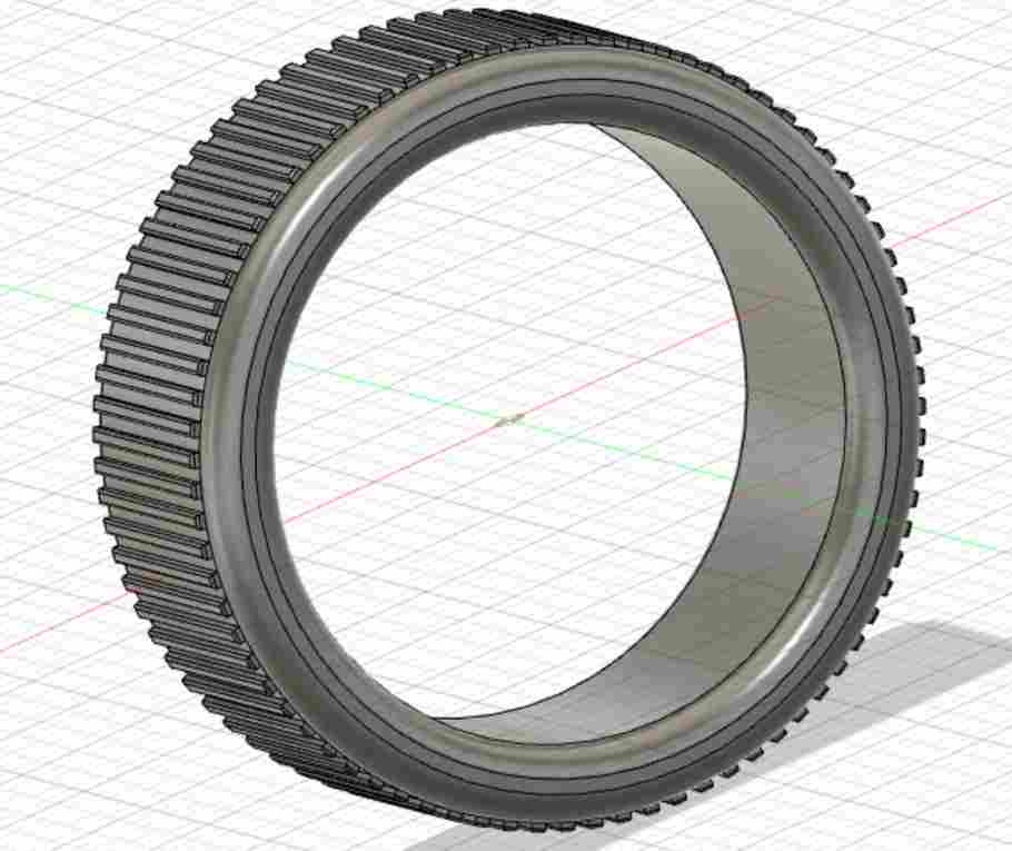
And finally, my brother charlie was worried that my design did not fulfill the 3D milling requirement so we added a larger fillet to the tire tracks:
We were pretty sure the mill would be able to mill these curved tracks as opposed to those tiny edges I had before. In addition, this design demonstrates the 3-axis milling. Whew!
CAM
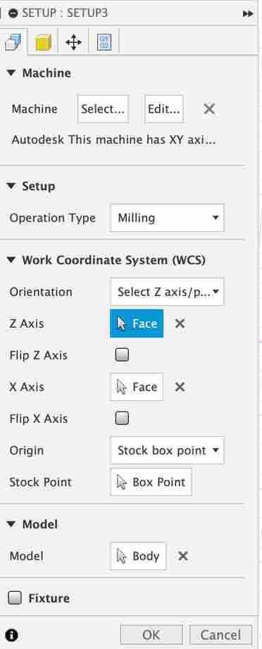
I followed these guidelines for the manufacturing setup:
Some steps seemed to be missing a little more info so this link also was useful.
One step that took down my machining time was to position the body at the top of the block that I measured:
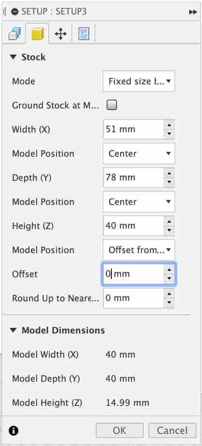
My other setup settings are shown below:
However, after following the Adaptive Clearing Steps in the link above, I was still getting this warning:
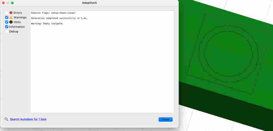
After some google searching, I saw here that some reasons for this error include: 1) Machining boundaries do not allow enough room for the tool to cut the desired part geometry. 2) Model selections in the CAM setup accidentally include stock bodies or omit the bodies to be machined.
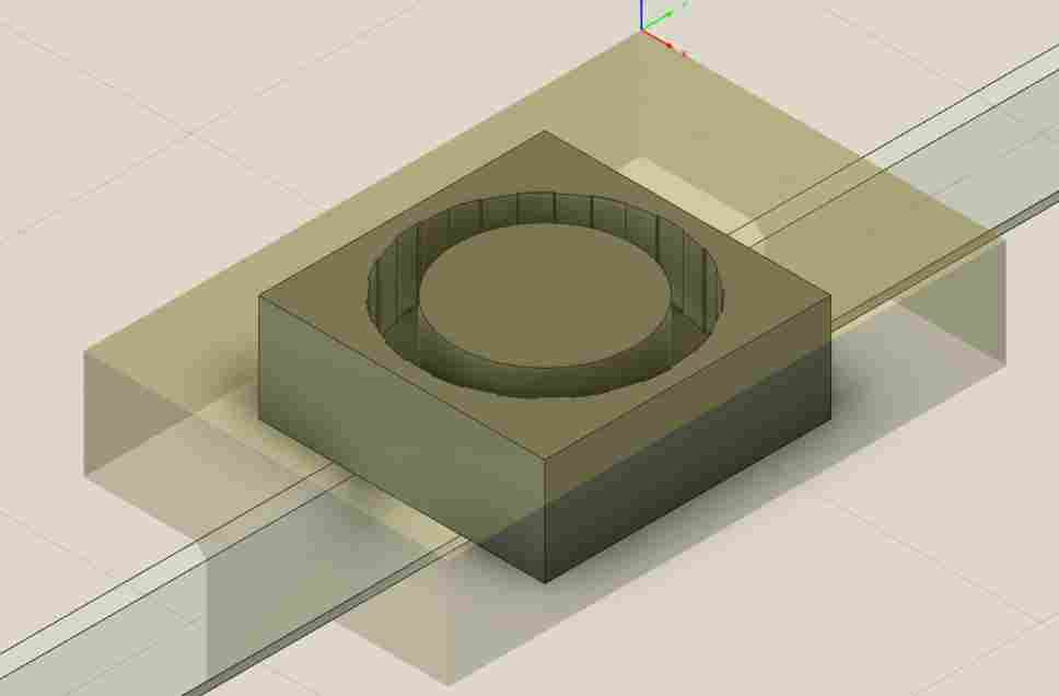
So I changed the width of the tire:
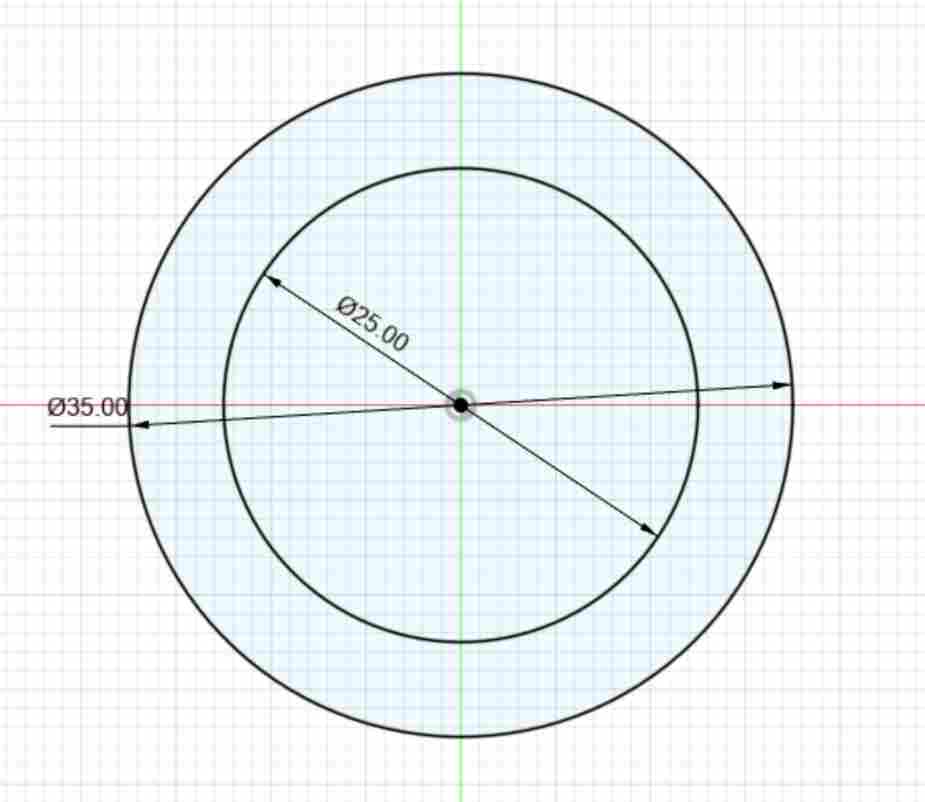
and immediately I was able to see the toolpaths right after:
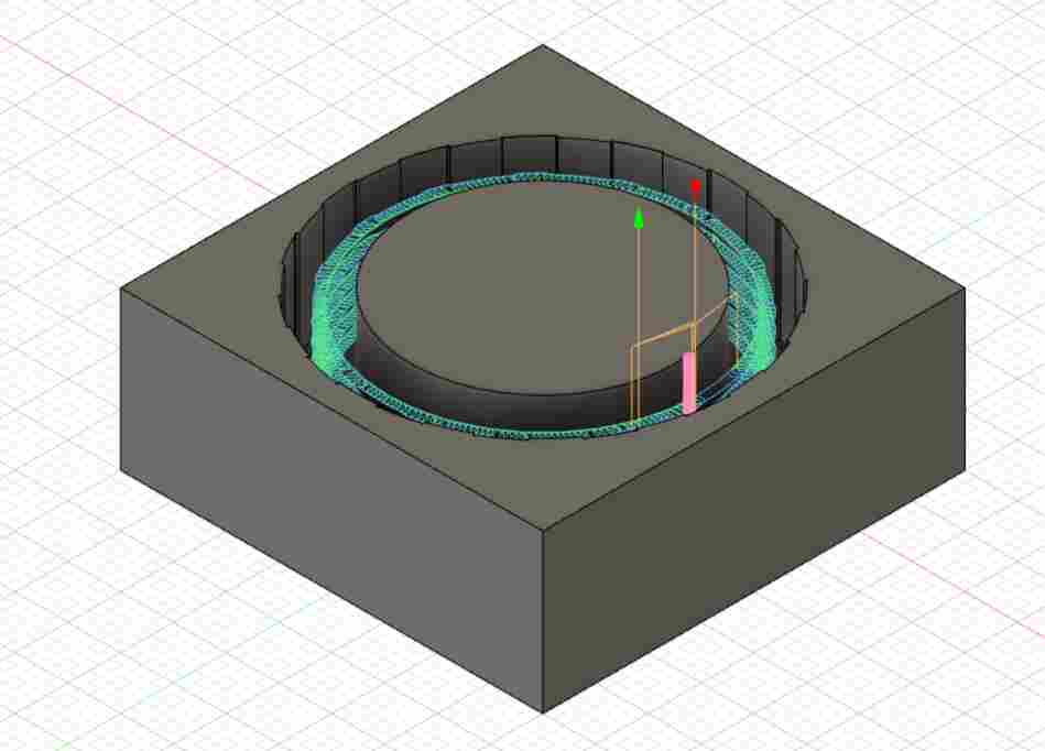
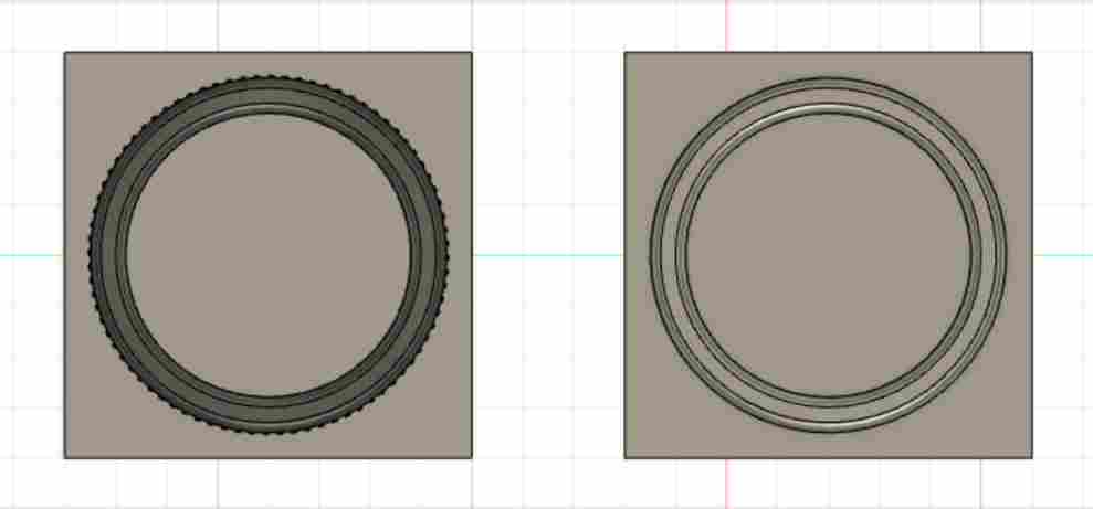
For the first pass, I left stock to leave:
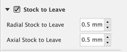
But then for the finishing pass, I made stock to leave 0. Also for the finishing pass, I selected Rest Matching so that it wouldn’t try to remill what it already had done:
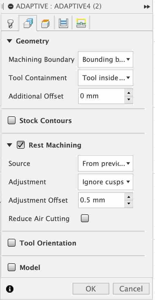
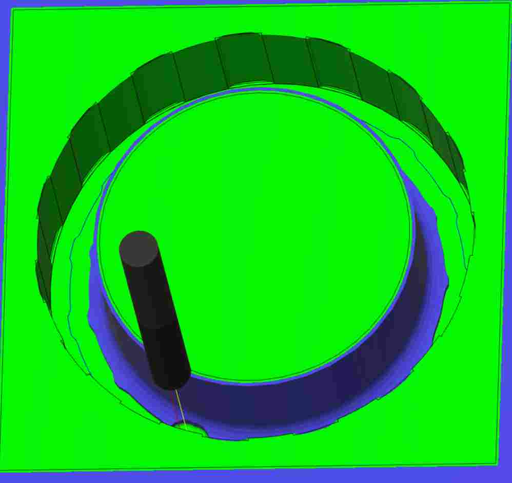
Otherwise, the two passes were identical. Both of these are using the 1/8 ball-end tool. I wanted to use a 1/16th or 1/32nd bit but the 1/16th bit was nowhere to be found and the flute of the 1/32nd bit was too small. After simulating both passes (right click –> Simulate):
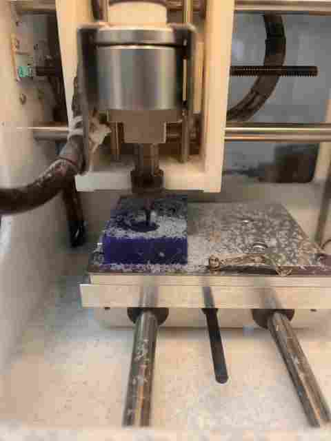
Bantam Mill
The original wax block was too tall for the mill unfortunately so I had to saw and sand the block in half and adjust the height of the gcode imported into Bantam.
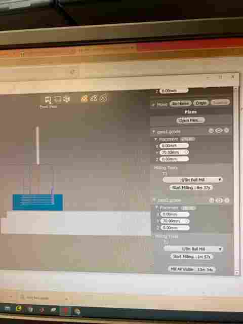
Then, I proceeded to follow the same steps I did for electronics week. However, probing the tool was not necessary when using wax.
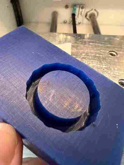
I used silicone rubber for mixing because my mold is hard and therefore, I needed to use a soft material for the cast. In addition, this seemed to be the most similar material to the wheel shown in the first image. I followed the steps detailed on the buckets - stir A and B separately using the folding technique to prevent air bubbles, mix A and B together with a 1:1 ratio, and then pour in the mold.
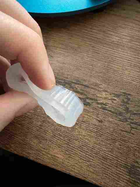
And using tweezers I was able to pull it out after 30 minutes!