5. Electronics production
For our group project work on defining our laser cutter’s specs, see here.
Before building our own pcb board, Charlotte Latin students completed baby steps to understand what is going on and what it means for something to be a “Programmer”.
What is a programmer?
I learned the programmer is what you use to program your processor. The code sits on the processor but the programmer is needed to send code to that processor.
What is a UPDI pin?
A UPDI pin is where you connect your programmer - it is the means at which you send your code.
Simple Hardware, Simple Software: Using arduino as the programmer and a bread board for the circuit
First step is to solder the ATtiny412 chip to the to the circuit board as shown below.
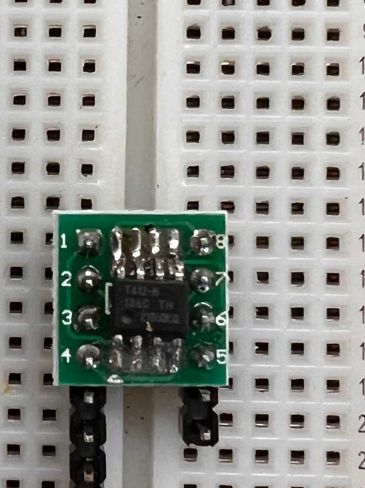
I discovered it was best to solder the input pins first and then the legs of the 412 chip. I also discovered soldering pins on opposite ends first helped keep the chip and circuit board in place. When soldering the 412 chip down I struggled to clear a bridge between two legs. I discovered heating the tips of the tweezers via the soldering iron and using the tweezers to clear out the bridge was the best approach. Next time I will use less solder to prevent such a large bridge from forming. After soldering was complete it was time to wire and program the circuit using the Arduino as the programmer.
To do this we followed these steps.
Problems encountered while following these steps:
- When downloading jtag2udpi as a zip file (step 2 under MAKE THE UPDI PROGRAMMER in the link sent above), it will download as
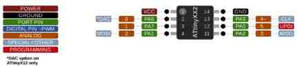
jtag2udpi-master.zip. We struggled to access the examples from this library so we unzipped the file, renamedjtag2udpi-mastertojtag2udpi(though this step shouldn’t be necessary), and then opened up thejtag2udpi.inofile in the Arduino IDE by double clicking it. This will open up a blank script, which confused us at first but uploading this script will set the Arduino Uno as the programmer. Before uploading, we needed to change Tools→Boards was set to Arduino Uno, rather than Arduino Nano as stated in the directions. Since the Arduino was plugged into the usb port on my computer, it was necessary to change Tools→Port to the one withusbserialincluded in the name. - When setting up the circuit board, I set up the circuit board using the wrong inputs. This in turn caused the LED light to stay on, rather than blinking. I learned that the input pins connect to the legs of the 412 chip by following the lighter green lines as shown below:
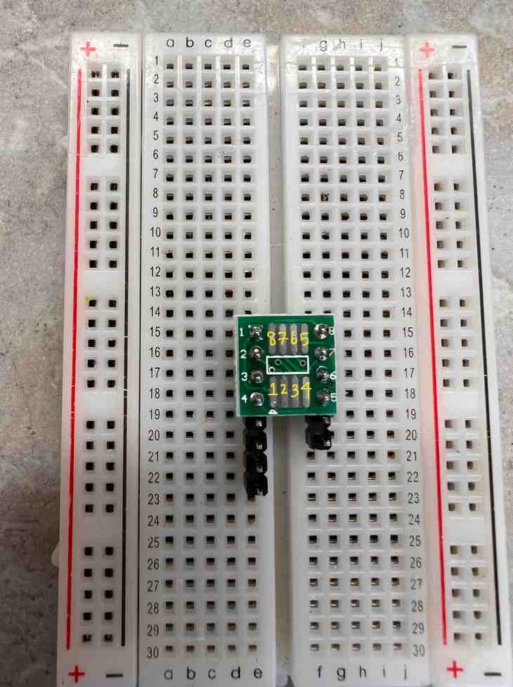
Then using the diagram of the circuit board shown in the link above, I correctly found which pin was the correct VCC, GND, and which digital pins I could put LED in. It is also important to note that the VCC is denoted by a circle on the 412 chip, so if you want your VCC input to be pin 1 then the 412 chip should be set up as two images above (412 chip soldered onto circuit board). -To make sure the 412 chip was soldered properly (i.e. no bridges) and ensure the power from my arduino was working we ensured the voltage between the VCC and the GND was ~5V as shown below.
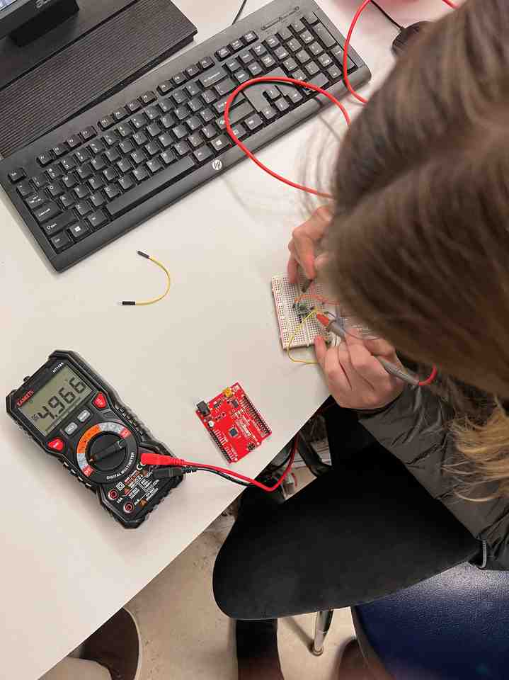
-
Instead of using a 4.7 kOhm resistor as shown in the instructions, we used an LED and uploaded File–>Examples–>Basics–>Blink to the 412 chip.
-
The last change I had to make before successfully getting the LED to blink as wanted was to change
LED_BUILTINin the code to whichever digital pin the LED was connected to. As shown below, my LED was connected to input pin #2
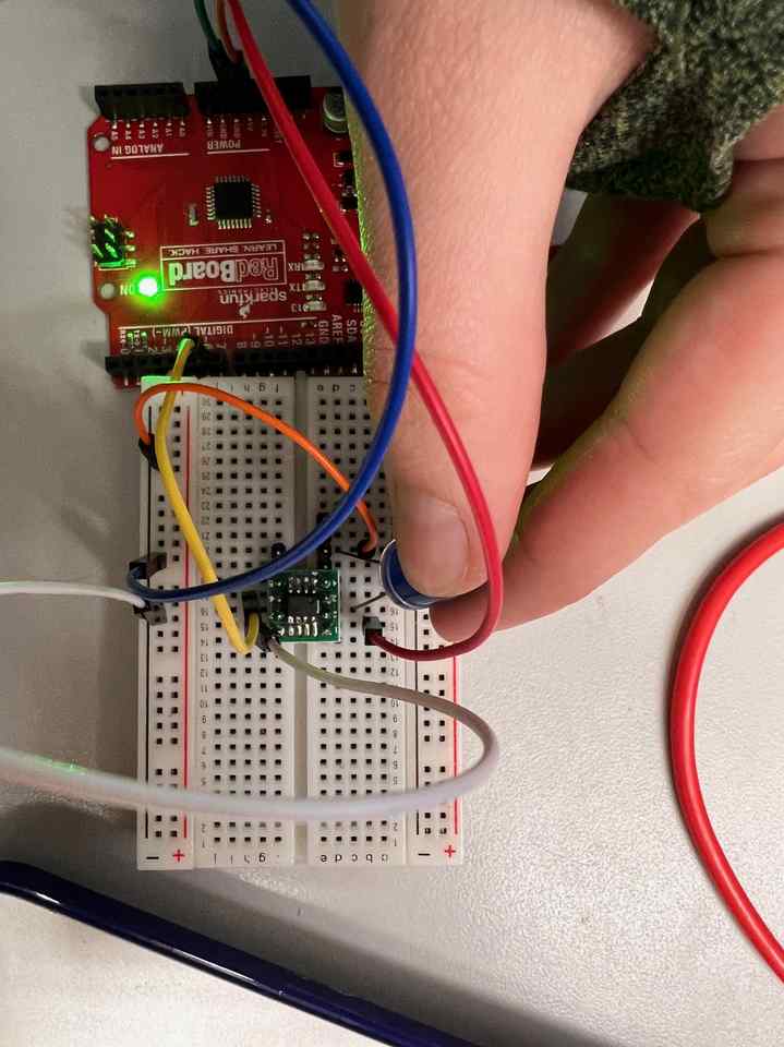
- But matching this to the diagram shown below and specified in the link above
I changed LED_BUILTIN to 0.
Below shows my LED blinking every second.
Click here if embedded video is not showing!
Complex Hardware, Simple Software: Making AtTiny412 General Purpose Blinky Board and UPDI Programming
We were given boards that were already milled at this step. Then, we followed these steps.
Problems I ran into/Things I learned:
- Once the arduino sends the code to the 412 chip (the processor) then all the arduino is doing is providing power
- Struggled to solder one leg down of the 412 chip but that leg is not being used in the circuit so it’s alright
- Had to remove 412 chip with the solder sucker tool and resolder when my circuit was not working
- White part of resistor goes down, black side faces up. Resistors don’t have polarity, LEDs do
- When making the Arduino the programmer, the avr “Programmer” needs to be selected as shown below:
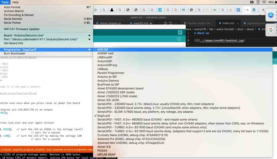
After this step, Arduino is the programmer and processor so wouldn’t need to be a UPDI programmer if this is all we needed. But, for this project we want to use the ATiny412 chip as our processor. So, once the Arduino is your programmer then changing the programmer to jtag2updi (as shown above (converts AVR microcontrollers - which includes Arduino) to a updi programmer.
Tips/Tricks:
- In order to tell which side is cathode (negative) and which is anode (positive) for an LED use the multimeter - if LED lights up then the multimeter’s red leg is on the positive end the black is on the negative. Also the green strip on the LED denotes negative
- To make sure code is good set up circuit from last week on breadboard and reupload
- Use multimeter across various parts of the breadboard to see what is getting voltage
- You could see the blinking code was working on various parts of the breadboard because the voltage readings on the multimeter were alternating between 5V and 0V. However, this was not the case when reading across my resistor, so I replaced the resistor and then my circuit worked as shown below:
Click here if embedded video is not showing!
*Complex Hardware, Complex Software: Making Our Own Arduino & Milling Our Own Board
Milling the board*
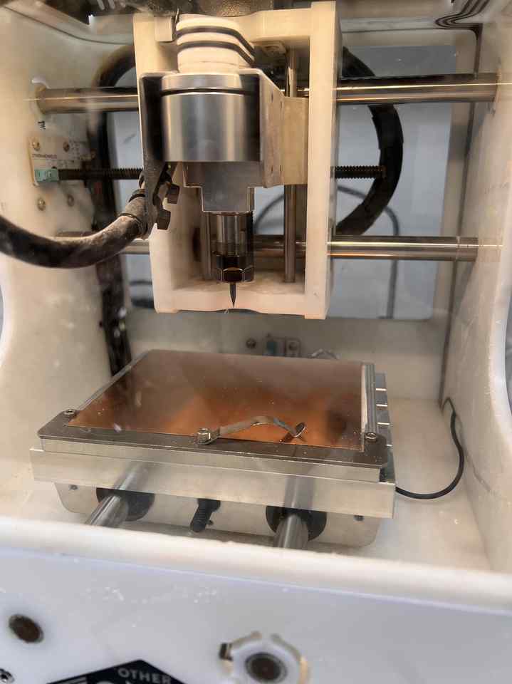
CNC
These were the steps we followed for CNC machine: Then, follow these steps:
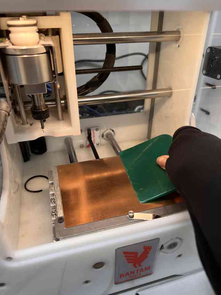
We used FR1 material and used a tool shown below to ensure that the FR1 was flat:
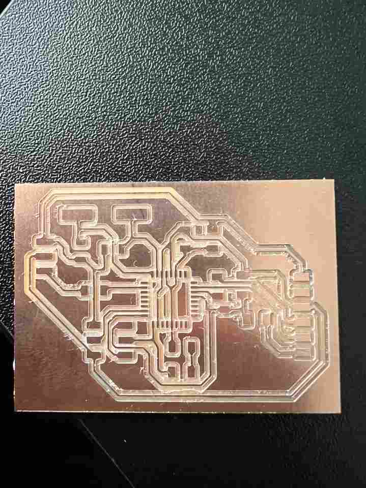
And uploaded this file to bantam. For this circuit, we needed two different tools for engraving and cutting. Bantam made this obvious because it will show red spots on the circuit if the listed tools are not capable of cutting that area. Bantam also tells you when you need to change your bit. For this project we used a 0.0005 bit and a 1/32 bit.
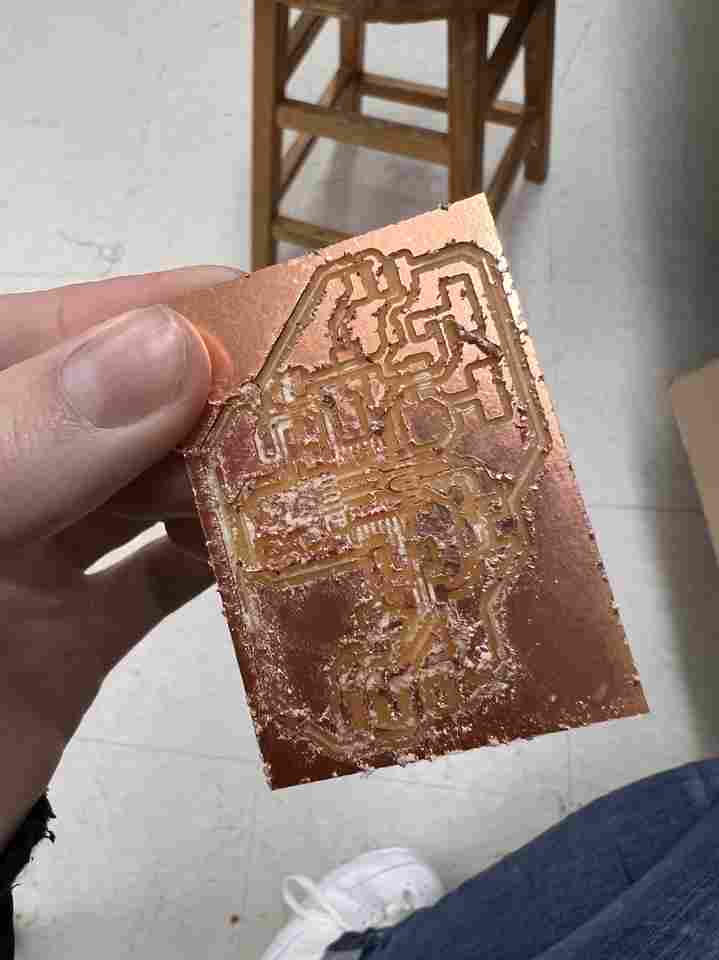
Once I correctly followed the steps listed above, I got this beautiful thing:
Problems I ran into/Things I learned:
- Always Locate the tool before probing and make sure to change material (basically make sure you actually read each step listed above haha)
- On the Bantam Software, to turn something off you highlight it
- My first attempt, I accidentally skipped the Probing step listed above and this was the ugly result:
- In order to probe, the metal clip needs to be touching it like below:
Using Board as the Processor
I soldered the components in place based on this circuit.
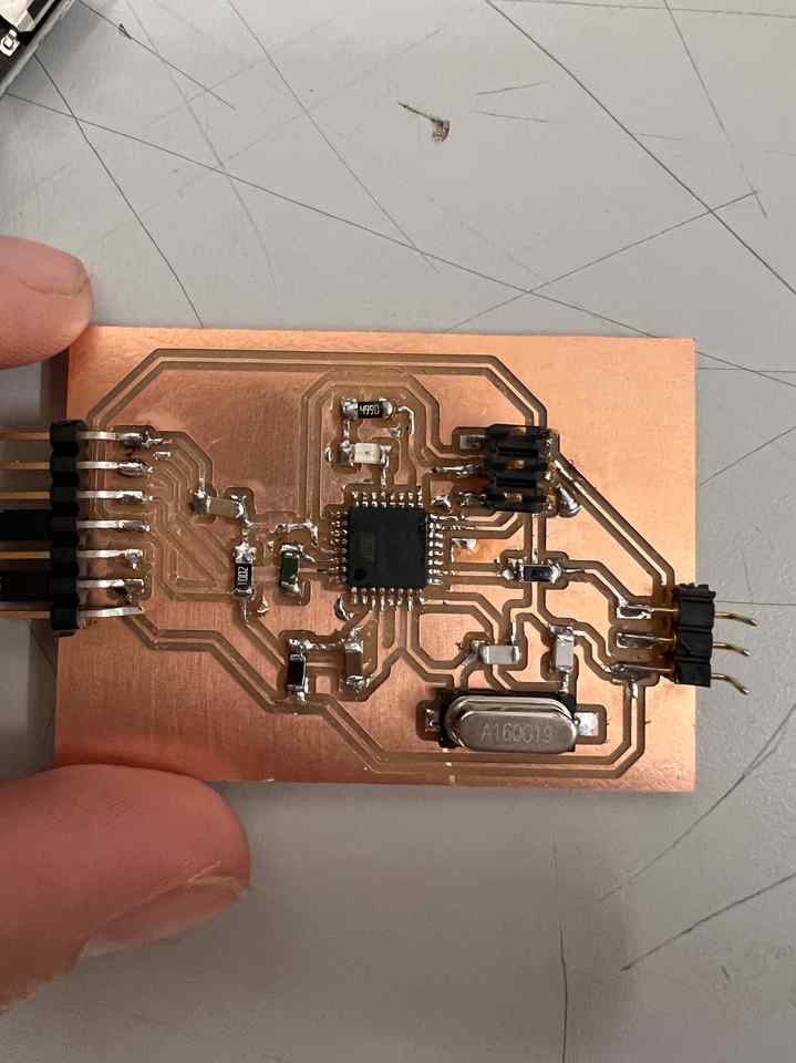
First I uploaded the Blinky code to the Arduino by itself with the LED_BUILTIN as the pin, the Arduino Uno as the Board, and AVRISP mkII as the programmer. This ensured the arduino was functional. Then, I changed the pin to 6 in the code and connected the 6th digital pin on the arduino to the UPDI pin on my board (found out later UPDI pin isn’t the correct pin to connect to). Unfortunately, this became quite a headache because my LED wasn’t lighting up. However, I got pretty good at debugging with the multimeter :) - The UPDI pin was alternating between 0 and 5V as expected. I moved along the circuit to ensure each component was doing the same. Eventually, with other student’s help, I realized I was supposed to connect to the SCK pin, not the UPDI pin, and the LED started blinking immediately:
Click here if embedded video is not showing!
What we did above is not using our board as a processor (I think), it just shows components are soldered properly (though the UPDI components aren’t tested with this LED test), the 328 isn’t fried, and we can program our AtMega328.
I then used this link to convert my board into a programmer with the Arduino as the ISP. In other words, the ArduinoISP.io code sits on our Arduino Uno, the jtag2udpi.io sits on our ATMega328 board, and then we can use our ATMega328 board to program. In order to burn the bootloader, I had to change BAUDRATE in ArduinoISP.ino to 115200:
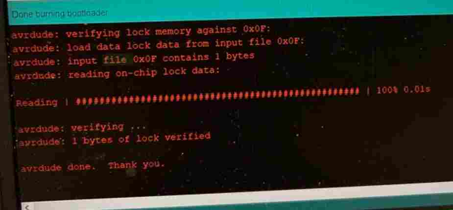
After I completed the steps above (used Arduino as ISP with 115200 baudrate and burned bootloader), I wanted to make sure it was working by sending the Blink code from my board to the Blinky board in the section above (Complex Hardware, simple software).
In doing this, I still had trouble with the baudrates. The Arduino Uno default baudrate is 115200 and the AtMegas is 9600. I tried messing with the rates specified within ~/Library/Arduino15/packages/arduino/tools/avrdude/6.3.0-arduino17/etc/avrdude.conf and the boards.txt file, but everytime I tried to upload blink the board, the verbose output said the baudrate was 19200. I believe this is the reason that I couldn’t upload code to the processor.
The Atmega328 datasheet was very helpful for this project.
SAMD Programmer
Since everyone was having trouble with the ATMega328 board, we all decided to follow these steps to create a simpler programmer. I was pretty fed up having to start over after all the work above so I didn’t document the milling & soldering process but it went relatively quick and smoothly and I had a working programmer within a couple hours.
Below is a video of the programmer working: