9. Embedded programming
Our group project can be found here.
This week we were tasked with using our programmer to program our board.
I followed the exact same process that I detailed in the electronics production assignment for programming a 412 board.
The programmer I made in the electronics production week is shown below:
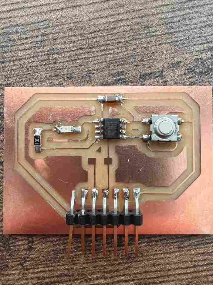
Programming Week 5 Board
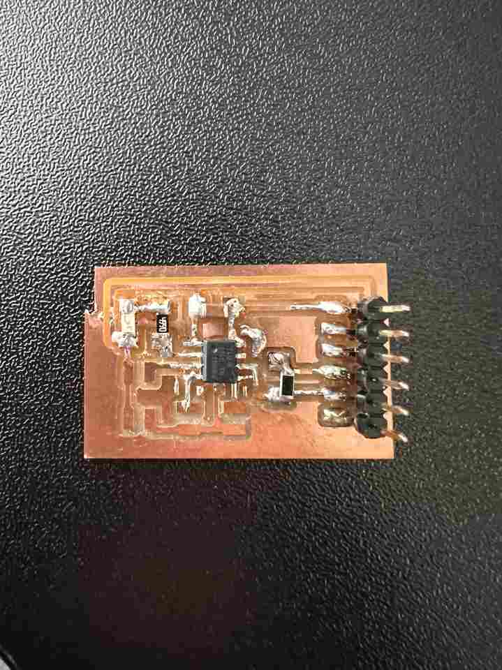
Below is an image of the board I made in week 5 (and boy have I gotten better at soldering since then!):
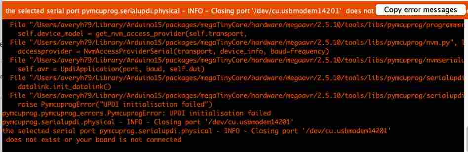
Everytime I tried to program a board using my computer I received this error:
Here are two videos of my programmer programming a board on two computers other than mine:
As you can see, something seems to prevent my computer from being able to program my board! The other two computers were windows so I expected it to be a Mac vs. Windows issue. However, this fab academy student ran into the same problem and he was able to rule out the issue being Mac vs. Windows based. This student’s issue was that he had something called wacom installed, which is not the case for me :( so my google search continued!
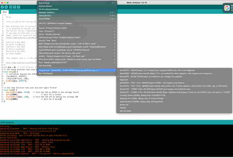
I exhausted google with all my searches and thought I was just flat out of luck. BUT, what happened next I cannot explain. I decided to try changing the programmer to a faster baudrate option:
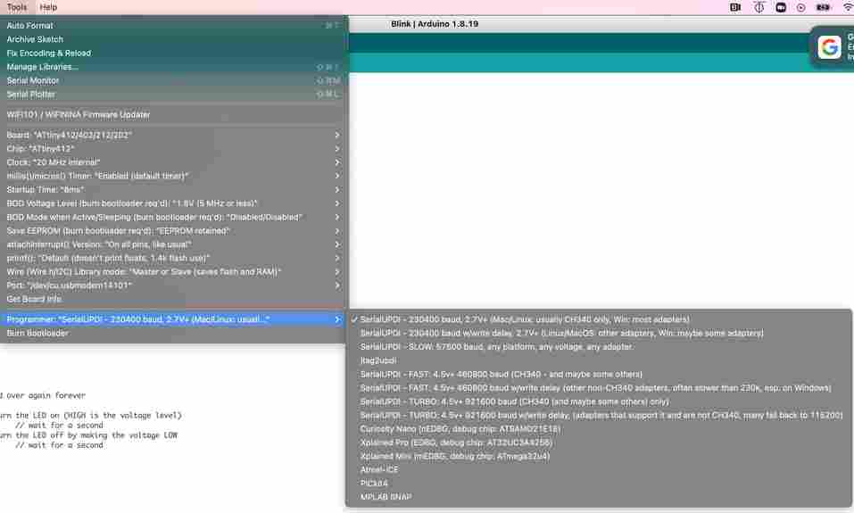
and my code uploaded properly!
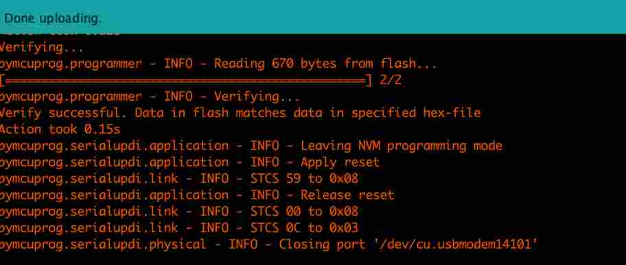
and my board was blinking every second like I asked it to! For documentation purposes I wanted to go back and copy and paste the error message that made me think I should test another programmer option, so I went back and reverted the change I just made (see Programmer in image below). To my surprise, the code uploaded again!
So for some ODD reason, selecting a different programmer once allowed me to upload the code properly and continue to upload code properly even if I reverted back to the programmer the instructions above say to choose. I never saw the error again once I did this! Yup…I don’t know…
Programming Week 7 Board
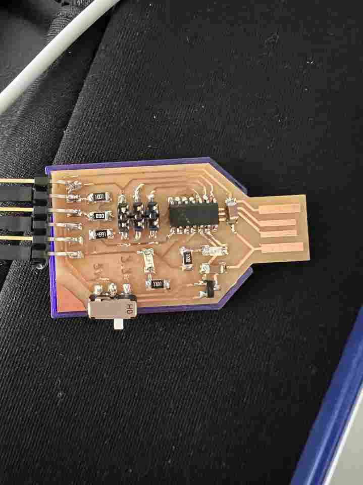
Below is an image of the board I made in week 7:
The other problem was that when I tried to program the board I made in electronics design, the LED would properly turn off when the button was pushed (aka the board was programmed) but then the LED would take awhile to turn off and occasionally turn off and on sporatically:
I expect this has something to do with clock frequencies; or, maybe because I don’t have the 4.9K resistor on the board. Turns out though, it was just a bad breadboard I had (which I had to use because I didn’t have male to male wires avaliable). UGH, that was quite a headache and it turned out to be a very simple fix but I feel like I should have figured this one out in less time. Once I used a different one, all was well:
SAMD11C Datasheet
Part of our assignment was to read the datasheet of our microcontroller chip. Although most of it was over my head, I was able to pick up a few key details. As always, the most useful part for me was the pictures and diagrams :) Below is a diagram of the SAMD 14 pin chip, used for our microcontrollers:
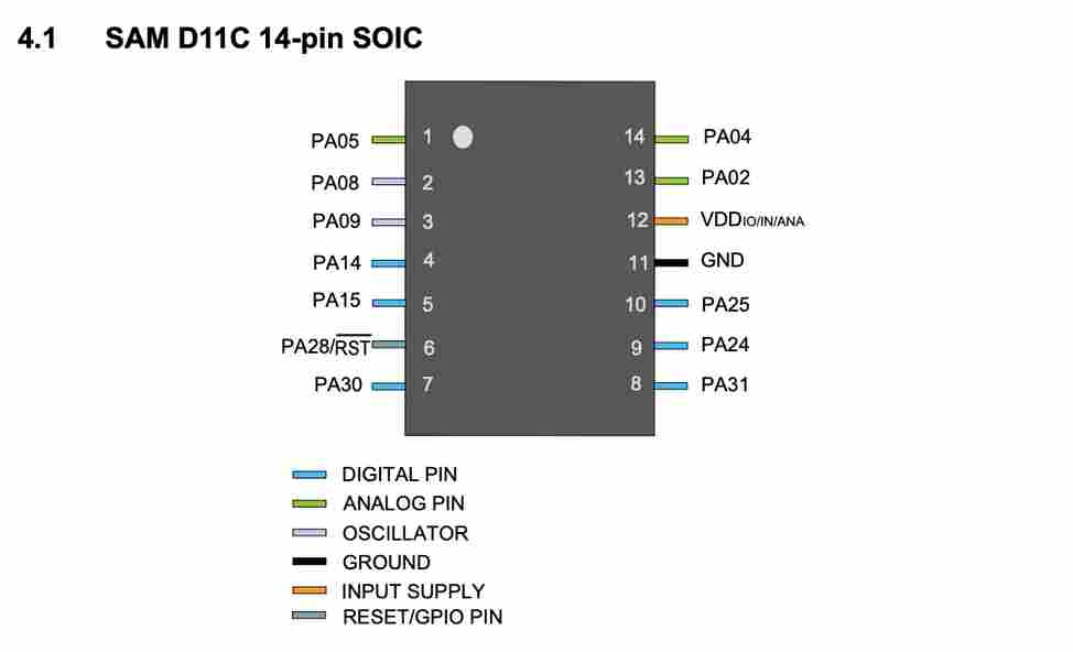
Some key specs I learned from skimming this datasheet are:
- 16 KB Flash Memory (Programmable Memory Size)
- Max CPU speed of 48 MHz
- Internal Oscillators: 32KHz, 32KHz ULP (Ultra Low Power), 8 MHz
- Maximum Voltage of 3.63V, Minimum Voltage 1.62 V, and so if the SAMD is interfaced with any signals higher than this supply voltage a current limiting resistor must be used. This explains why we had to use 3.3V to program our SAMD chips. However, Dr. Harris says the SAMD chip can still output 5V to a target board - which is why we put a sliding switch on our programmers between 5V and 3.3V.
- -40 to 85 degrees Celsius temperature range
- Supports ADC (Analog to Direct) and has a ADC resolution of 12 Bits and ADC sampling rate of 350 K Samples/Second
- 8 PWM channels
- USB support
This chip is capable of multiple communication types: * USART (Universal Synchronous and Asynchronous Receiver and Transmitter) - i.e. RX and TX * SPI (Serial Peripheral Interface) - MOSI, MISO, SS, SCK * TWI (Two Wire Interface - I2C) - SDA and SCL