Football Catch & Throw
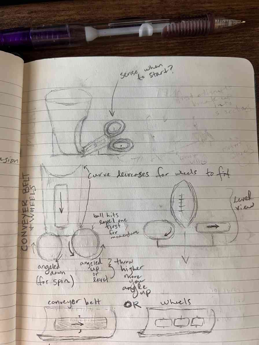
Although football throwing machines already exist, they all are over $2500 and require you to manually position the football in the machine for it to throw it back. An example of one currently on the market is shown below:

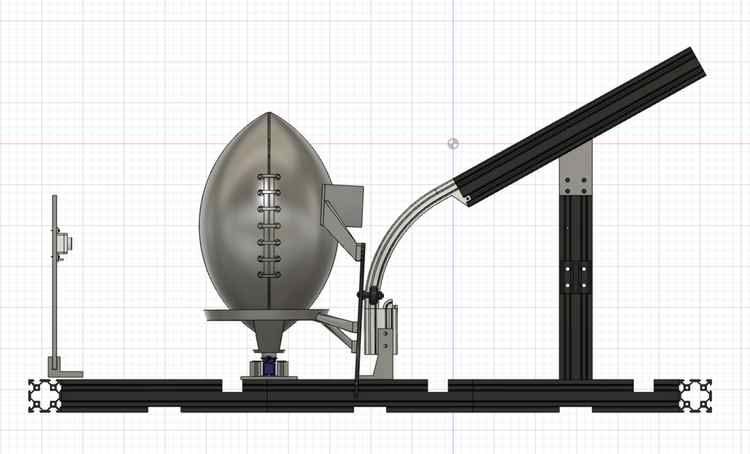
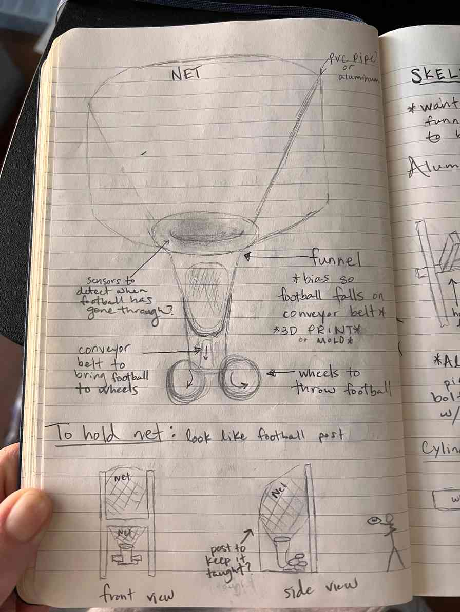
A similar design to this will be used for the throwing of the football but additional design is needed for automating the positioning of the football to catch and throw back. The idea is that a person throws a football into a net, this machine funnels the football down, and the football moves up a small conveyor belt to the two wheels that will throw the football with spin.
Short Term Problems to think about:
- Cheapest/Best Method to position the football with the laces pointing up (mechanical or sensor solution?)
- How to minimize the number of components?
- What is the cheapest way to build and iterate?
- How can I make sure I am safe at each step
Long Term Problems to think about:
- Can it deal with different sized footballs?
- How to bias the football so it falls correctly on the conveyor belt?
- No current plan for an on/off switch or how to plug it into the wall
- Could we mold a case so there are no exposed electronics and the machine is rain/weather proof?
- How to make the structure easily storable and compact
- How to make the structure easily movable and adjustable to the user for different sized footballs, throwing at different angles, throw it further, etc.
Spiral Design / Order of Design for FabAcademy
- Conveyor Belt: After a football has been caught, this apparatus spins the football to find the laces and then moves the football up to the throwing wheels
- Sensors
- HC-SR04 Ultrasonic Distance Sensor: Detects if a ball is present and ready to be positioned. Also detects where laces are.
- Two Stepper Motors: One 28BYJ-48 stepper will spin the football for finding the laces and the other taken from an Ender 3 will be used for bringing the football up the conveyor belt
- 1-2 Limit Switches
- Pulley System
- 3D printed cup to spin the football while finding laces
- 3D printed ring to push the football up the ramp
- 3D printed guide rail to bring the football up the ramp and guide the football from a vertical position to a horizontal position
- 3D printed V cup to hold the football as it moves up the ramp
- Sensors
- Throwing Wheels
- Catching Funnel
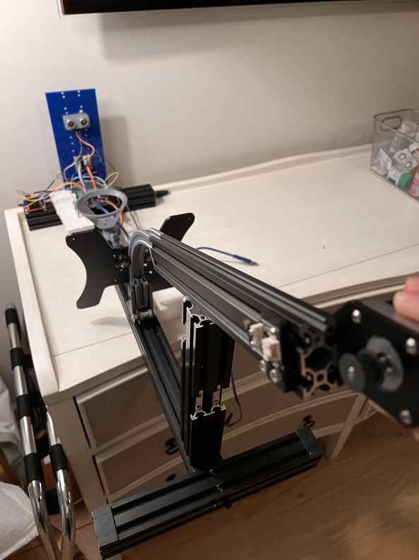
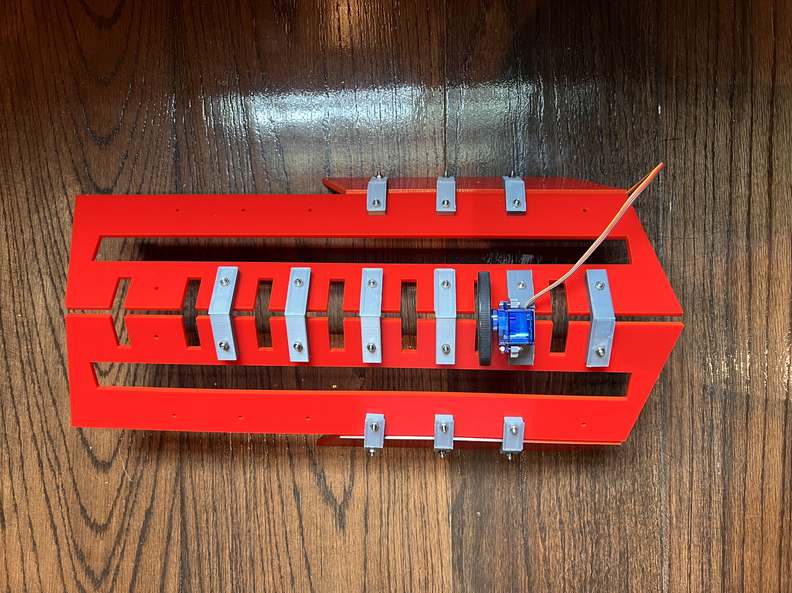
Current State of Design
DON’T WORRY THESE HECTIC WIRES WILL BE FIXED BY NEXT WEEK
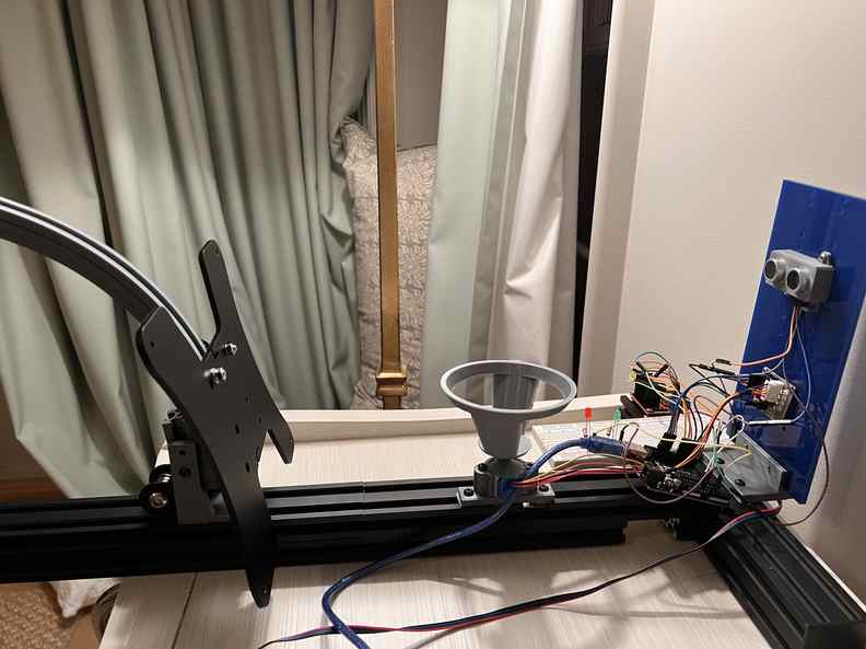
Finding the Laces:
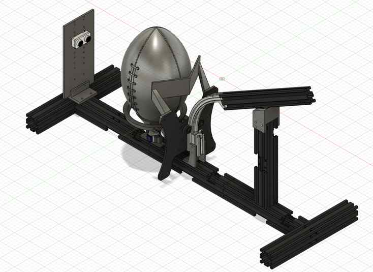
Full Aperature Design Iterations

The Iterations of Each Component
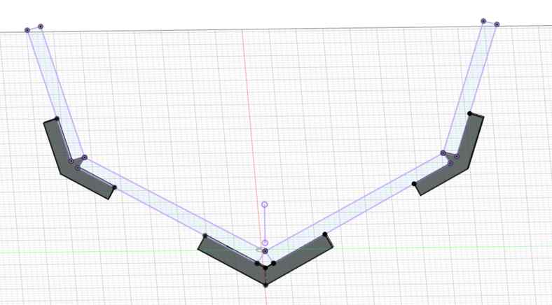
Funnel: Catching the Football
After using a blender physics simulation, the opening of the first funnel design (see here) would not allow a football to fall through:
So the opening needed to be redeigned. See how this was redesigned here:
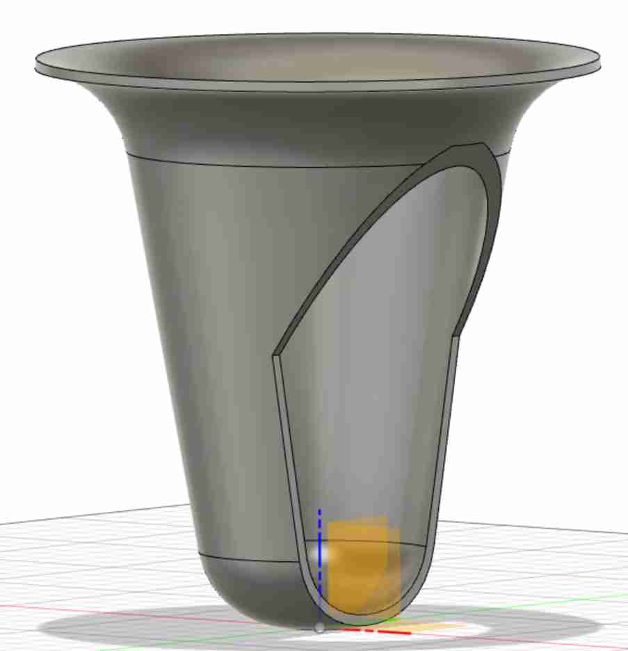
Although the shape would allow the football to fall through, the football would get stuck leaning against the side of the funnel:

Conveyor Belt: Positioning Football and Moving Football up to the Wheels to Be Thrown
A more detailed look at the conveyor belt and wheels is shown below:
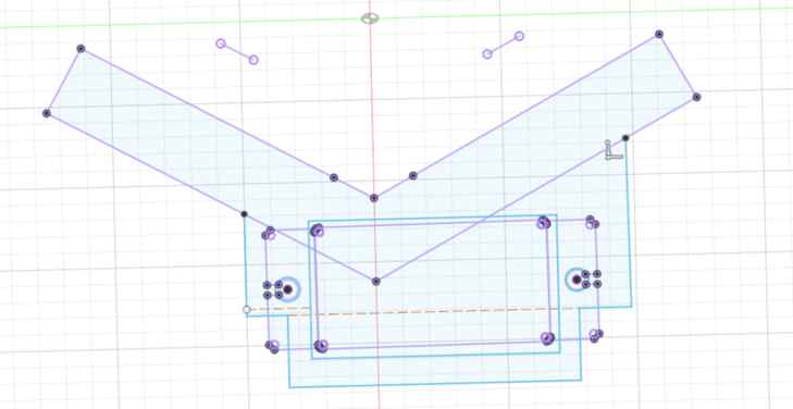
In the next iteration, I changed the shaft V shape to help keep the football in place:
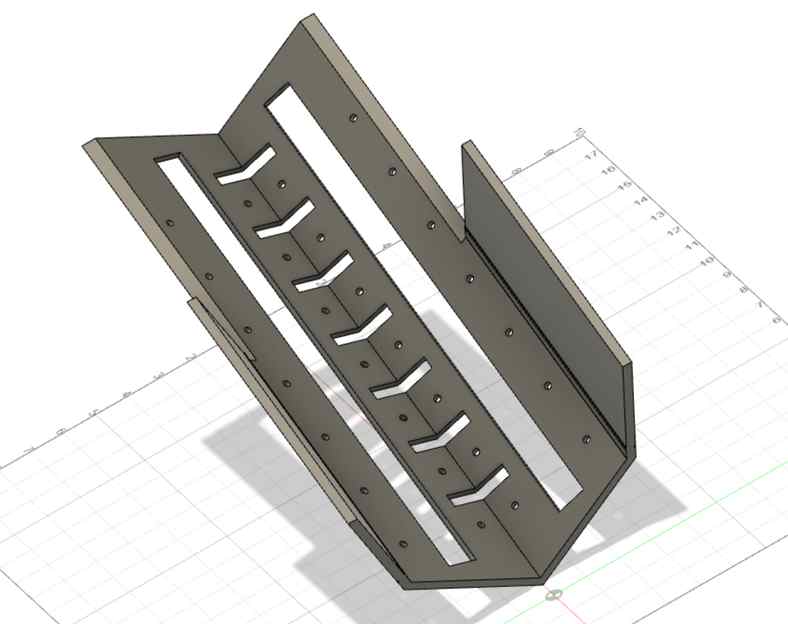
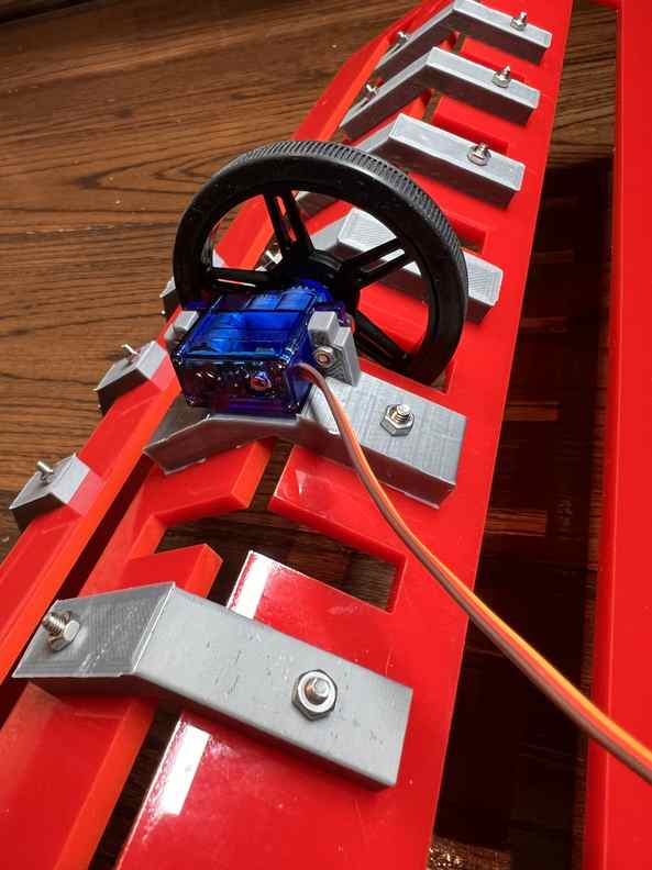
The horizontal slots in the design above are for placing the FS90R servo with a wheel:
There are numerous horizontal slots so that the placement of the servo can be adjusted. The vertical slots are for the pulley system to bring the football up the belt.
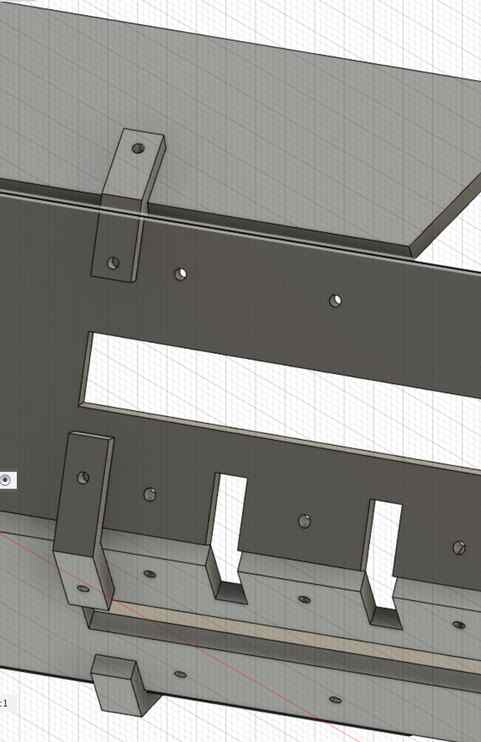
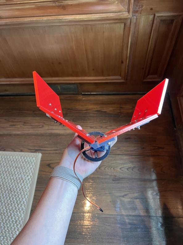
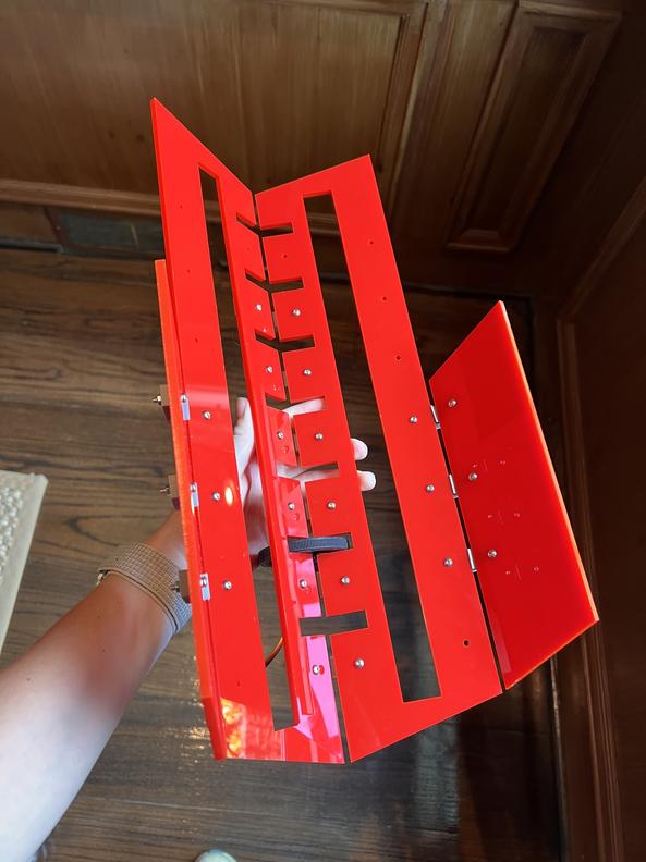
I exported an outline of each sketch as a dxf, laser cut this design on 0.25” acrylic, and the result is shown below:

As you can see each part is screwed together. In order to do this, I had to design joints:
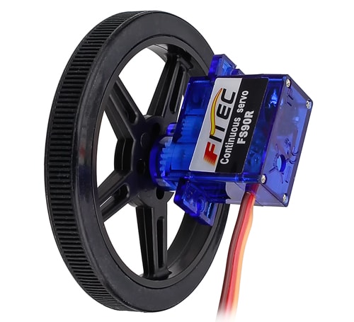
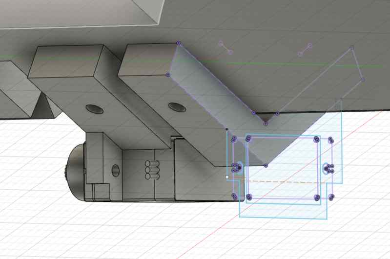
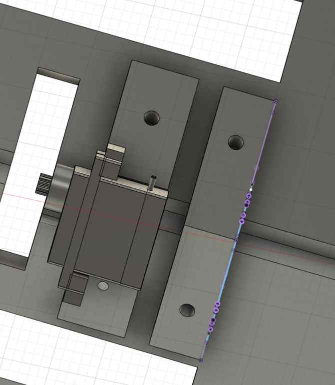
I also imported the FS90R CAD design that I used for the pulley system (see below) into the fusion design to design a joint that will also hold the servo. First I had to position the servo correctly relative to the conveyor belt so that the end was poking out of the belt’s slot:
And then extrude a combination of the projected joint and servo sketches:
After 3D printing these joints, I used M3 screws and nuts to put everything together:
As shown in Inputs Week and Outputs Week below is a video showing the FS90R servo moving when the HC-SR04 Ultrasonic sensor senses an object within 8cm of it:
A football weighs a little less than a pound so two to three of these little servos should be able to spin the football. However, the more I thought about it I didn’t think it was a great long term solution. Instead, I theorized that the ball could be pushed up the ramp. My design shouldn’t have to change that much but instead of the FS90R servos, I can use a stepper motor with a belt in a similar fashion to how the Ender 3’s designed. To do this, I needed to change the slots of the laser cut apparatus to be open at the end and I could remove the slots for the wheel since that would not be needed anymore:
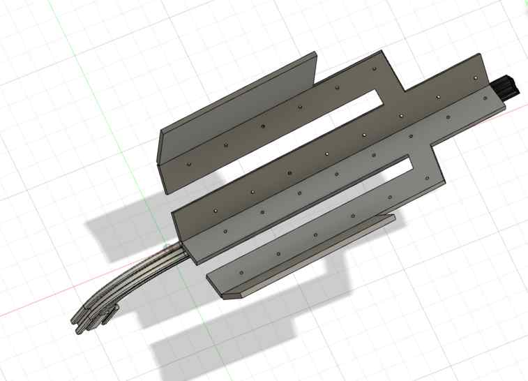
As you see above, I also made the end of the belt slimmer to leave room for the wheels. The aluminum extrusion beneath serves multiple purposes: 1) hold up the ramp 2) The belt connected to the stepper and ring will move along this extrusion, similar to the design of the Ender 3. 3) Guides the football from the stepper that rotates the football for finding the laces to the ramp
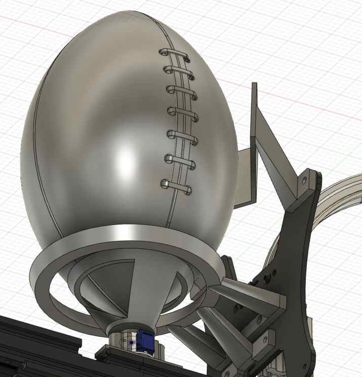
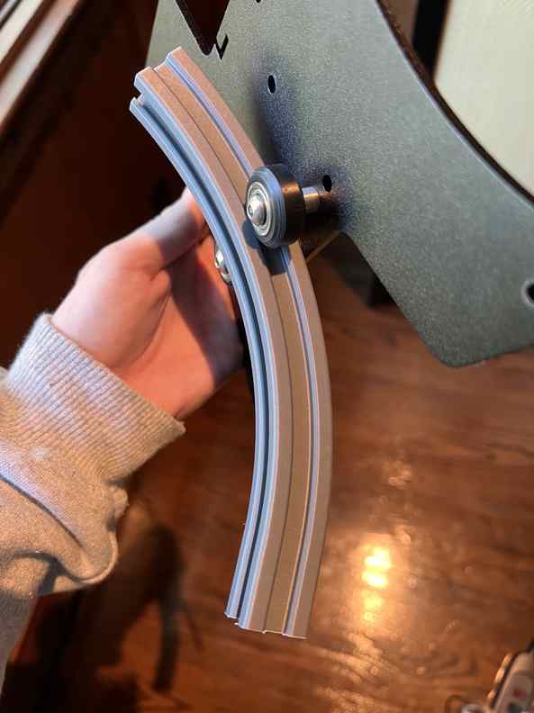
The 3D printed, curved portion (see below) of the aluminum extrusion takes care of (3). This curved “guide rail” helps limit the amount of moving parts with this entire aparatus:
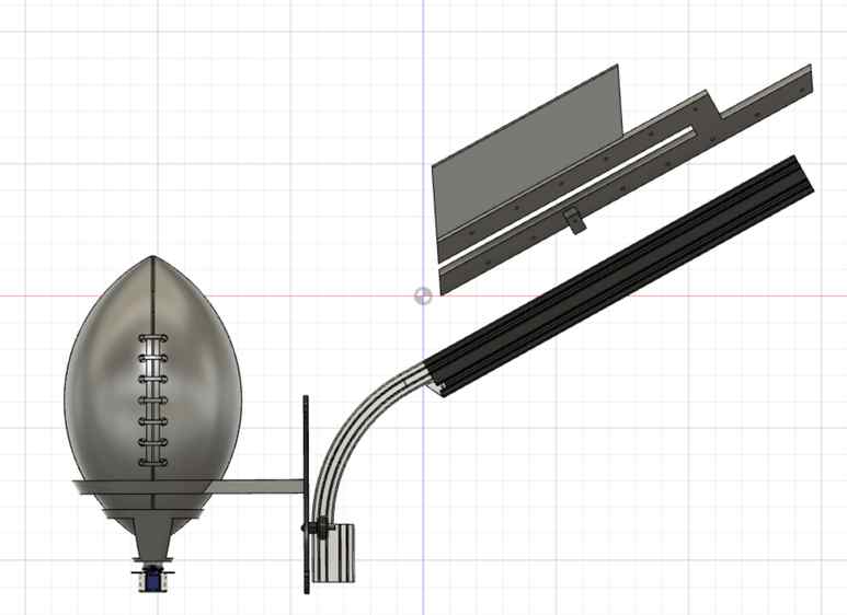
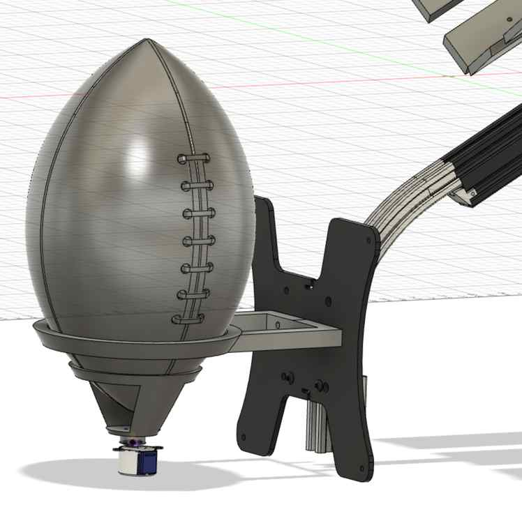
In the last picture above, the cup on the bottom stays in place and is connected to a 28BYJ-48 Stepper Motor. This stepper motor will rotate the football so that the camera can find the laces on the football. Once the laces are found, then the stepper with the cup will stop and the stepper that moves the ring and football up the ramp will begin:
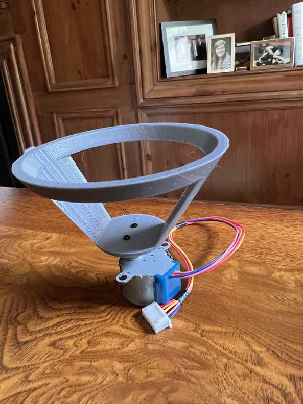
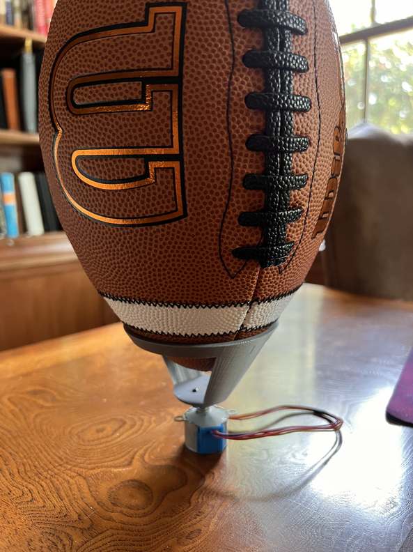
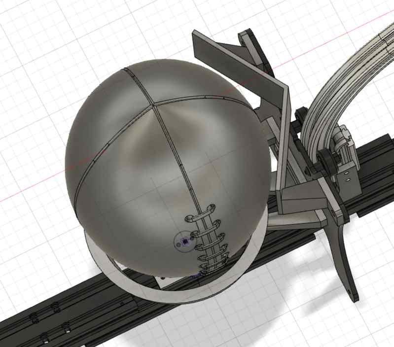
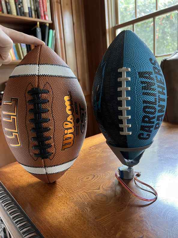
It was a lucky accident but turns out the cup works for multiple sized footballs!
As you can see, this stepper spins the football just fine!
Pulley System: Pushing Football Up System
Finding the Laces
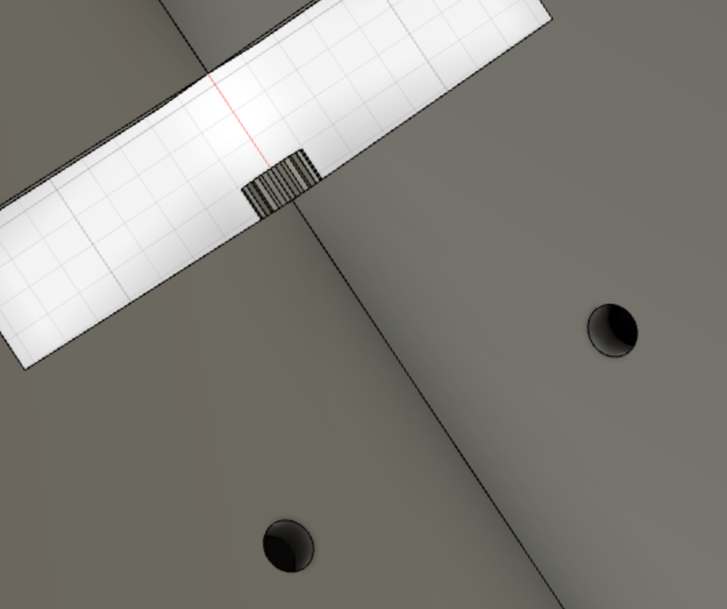
I had a few HC-SR04 Ultrasonic sensors laying around so I decided to follow this tutorial and see if there was a noticable difference between the distance to the laces and the distance to the ball where there are no laces. Aaaannndd nope. The sensor only measures in integer centimeters so it is not precise enough to see the difference in these distances. I almost didn’t even try to run the sensor across the laces when I noticed its precision. But, I tried just for the heck of it and WOW. To my surprise, there was a HUGE spike everytime the sensor came across the laces! And no, not because the sensor is detecting the milimeter difference between the laces and the ball but because of this concept:
Ultrasonic sensors do not work well on “bumps” because the sound signal it transmits may be reflected in a different direction. So, virtually every time the laces pass by the sensor the receiver doesn’t “receive” the signal and thus outputs a huge distance: