4. Computer controlled cutting
This week I worked on vinyl cutting, 2D software, parametric design, and laser cutting.
For our group project work on defining our laser cutter’s specs, see here.
Vinyl
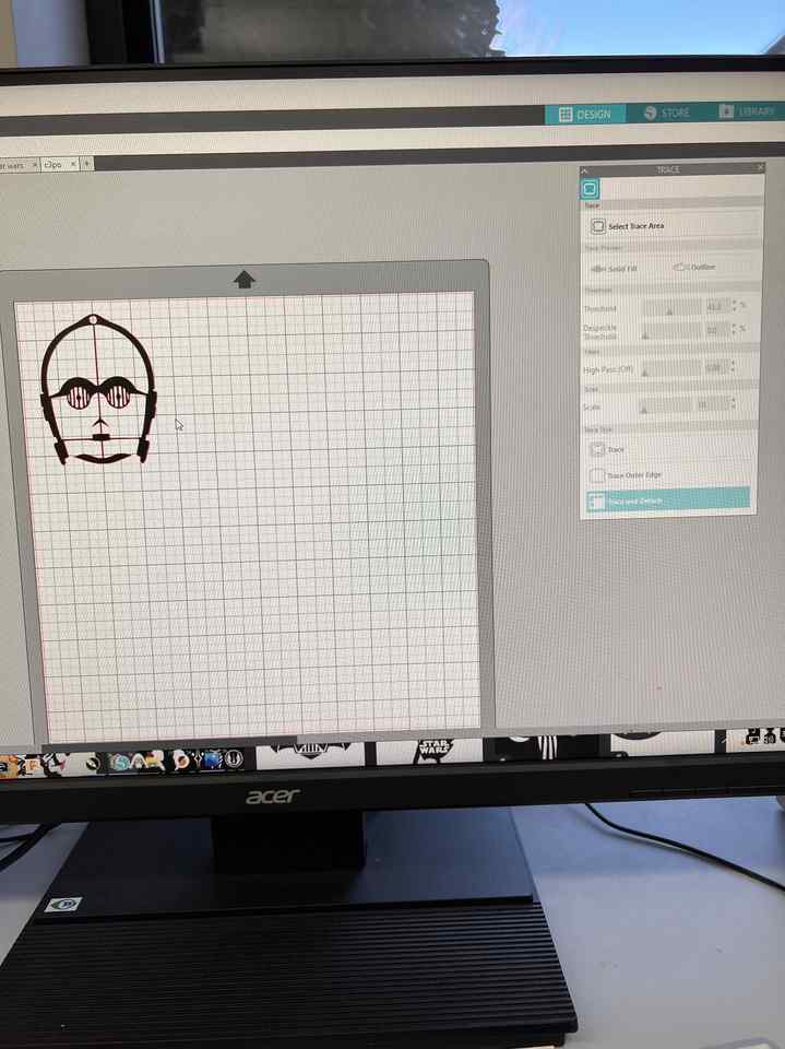
I found the picture of C3PO on google images that I wanted to vinyl cut. I saved the image on the computer connected to the viynl cutter and imported it into Silhouette Studio.
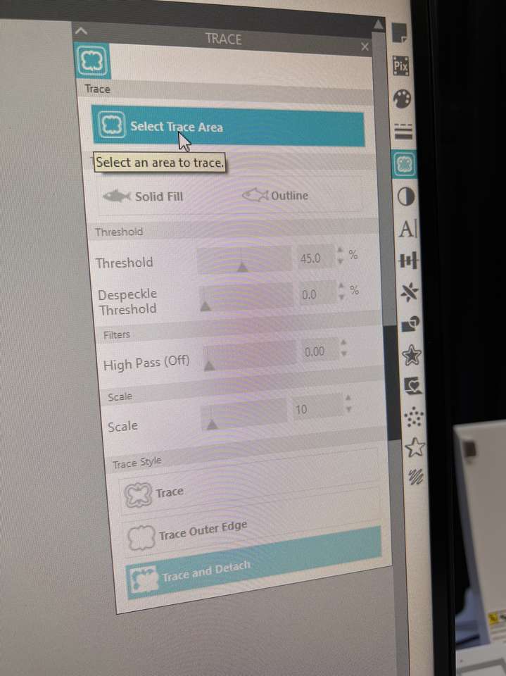
I clicked the butterfly looking symbol on the right hand side, clicked Select Trace area, put the trace area around my image, selected Outline, and Trace and Detach as shown below:
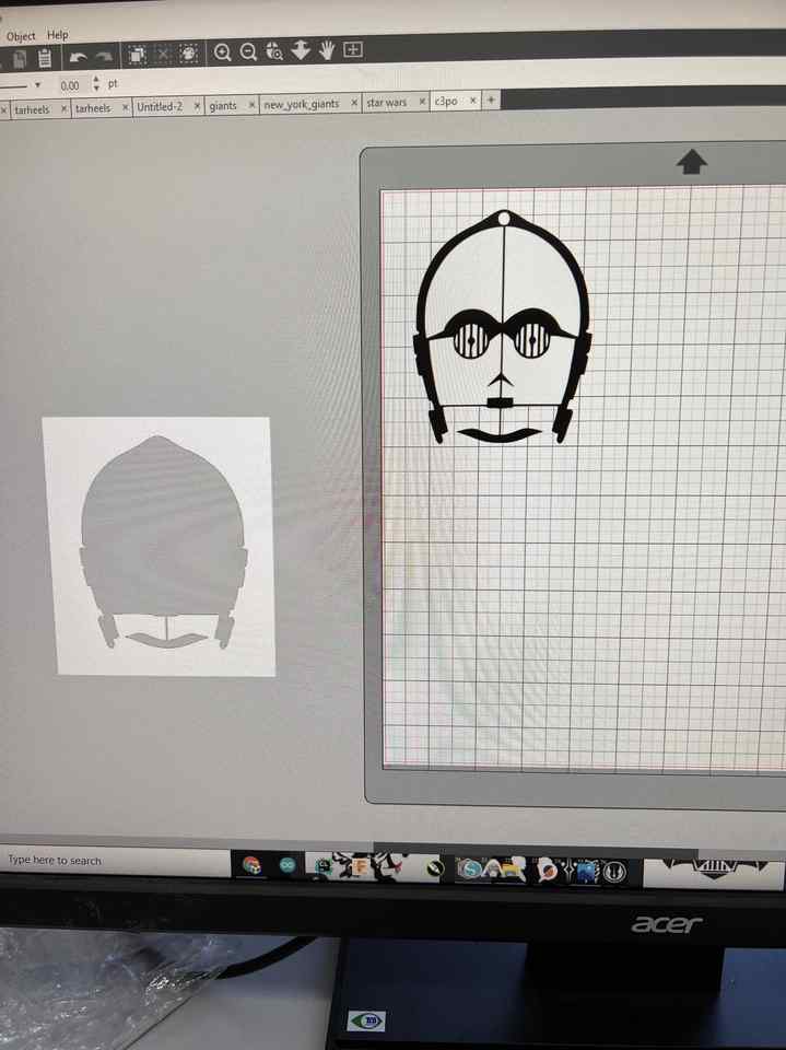
However, once I detacted the trace there was still unwanted white area in the middle as shown below:
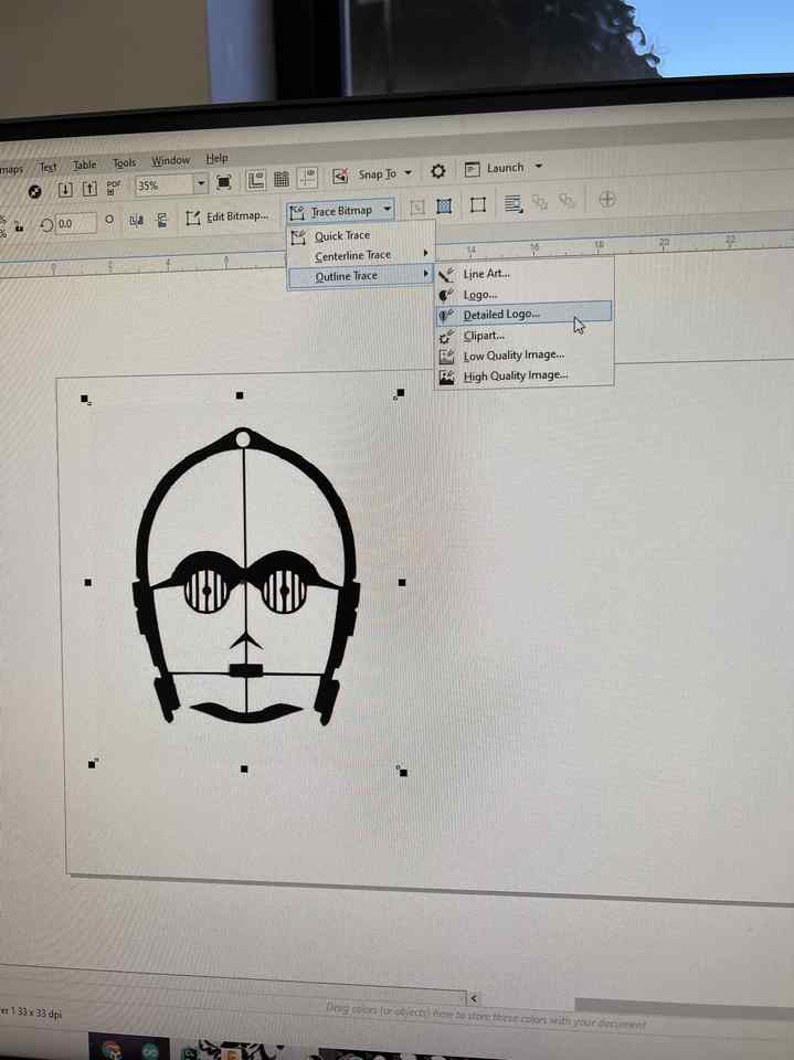
To fix this, I opened up the image in CorelDraw and Selected the dropdown option shown below:
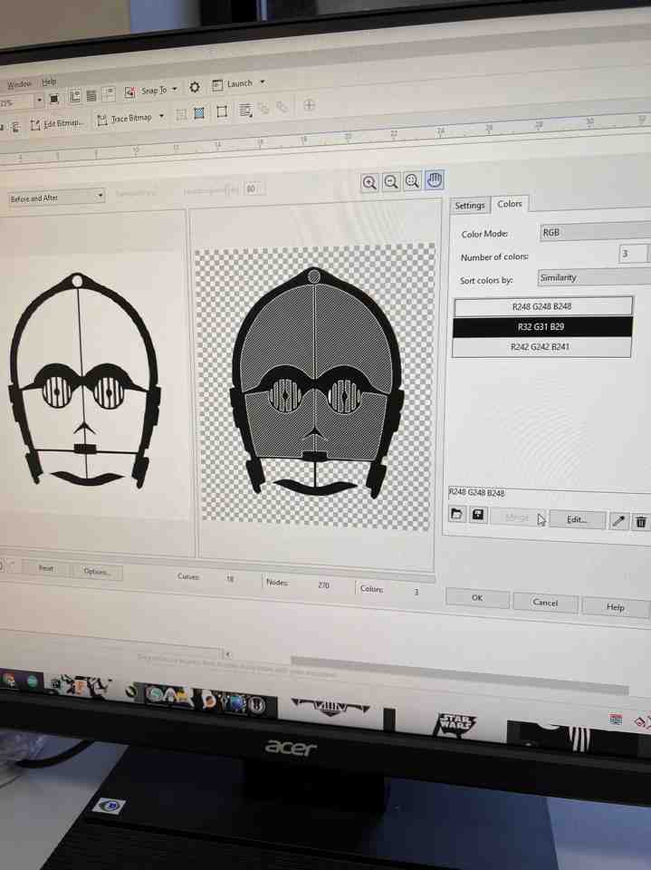
Turns out the problem was that there were slightly different shades of white so I had to Ctrl Click the different shades of white shown below in RGB format on the RHS and use the Combine Color option.
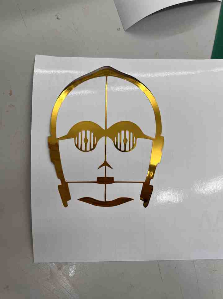
After that, I exported the image as a png and imported this png back into Silhouette. This time and scaled him down to 3 inches.
Then, I placed my desired viynl color (gold of corse) in the top left corner of the sticky mat next to the vinyl cutter. I selected “Load Board” while feeding the cutter the sticky mat and clicked “Send” on the Silouette software. Then I used tweezers to pick out the unwanted areas.
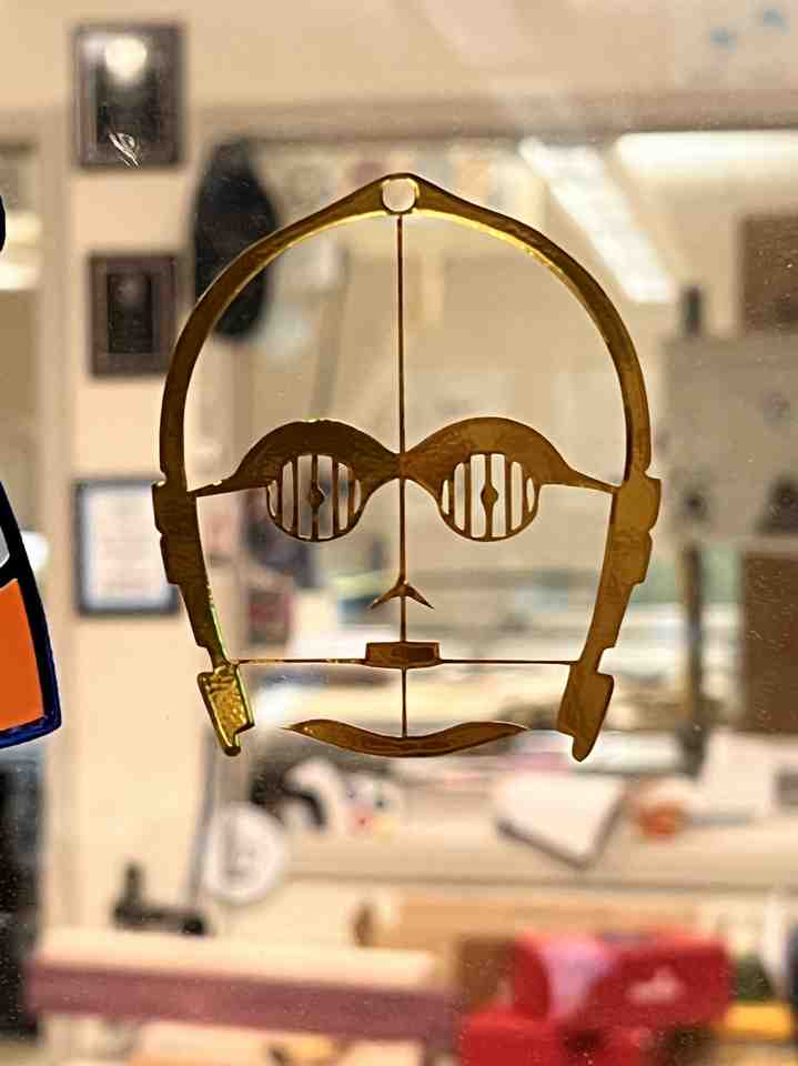
I then placed the clear sticky material on top of what is shown above. Once I want to put C3PO somewhere, then this clear sticky material will pull him off of the white backing. Finally, I placed the sticker where I wanted it - on the Charlotte Latin sticker window.
The final png can be downloaded here.
Parametric Modeling for Laser Cutting
I decided to make a finger joint box for the parametric construction kit assignment.
How will it be parametrically designed?
I would like for my final project to be parametrically designed so that if I want to make a certain part bigger, then the necessary parts will also get bigger. So, for this project, I want to make sure that if I change one dimension of the box, every other dimension will scale appropriately and both sizes will cut without needing to change anything else. I also wanted to make sure that by just changing the thickness of the material, I could print the same box for multiple materials with this design and the corners for each material would be flush.
Building The Box
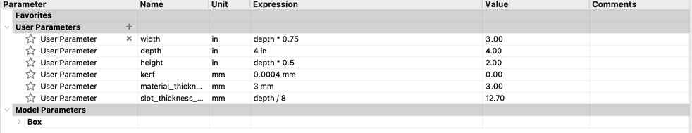
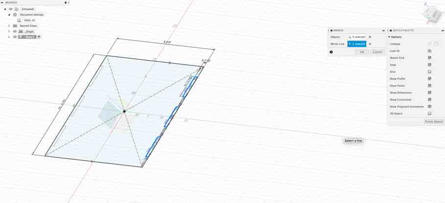
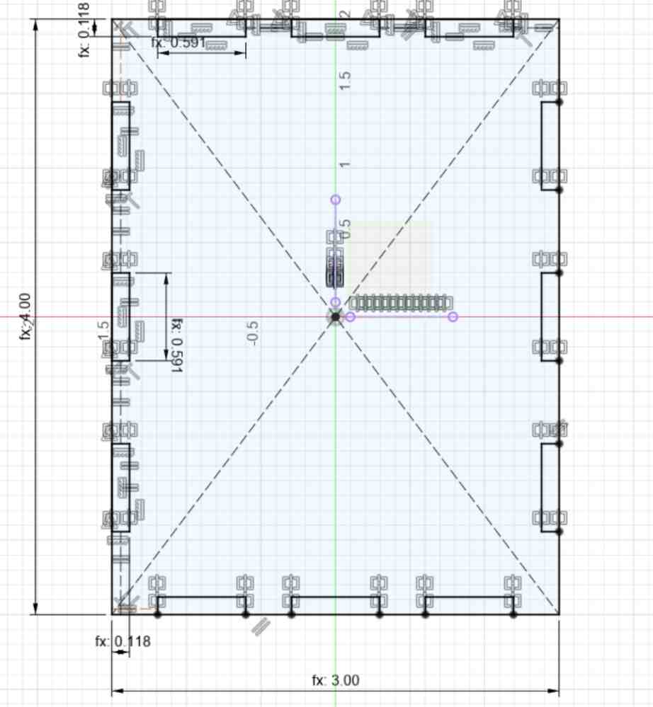
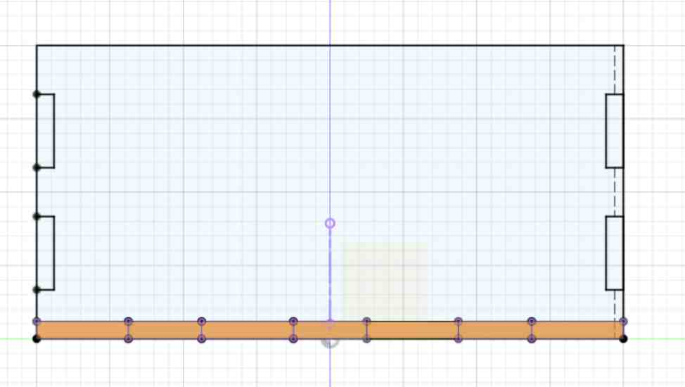
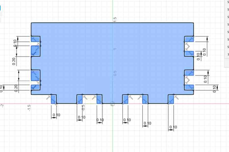
I started out by creating a center rectangle with the center being the origin. If the box is centered around the origin, it makes it easier to use the mirror function later on. I scaled the rectangle by width and depth as defined in the user parameters. I modified the parameters and named them width and depth by going to Modify –> Change Parameters. The final list of all of my parameters is shown below:
Making the slot sizes, height, and width a function of depth is what will make this design scalable. To Draw the slots I made rectangles on the edge of the rectangle and added constraints ensuring that the slots were equal and perpendicular to the edge:
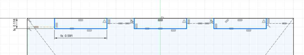
Then I used the mirror function to copy the slots to the other side of the rectangle:
I repeated this process for the other edges of the rectangle and extruded the sketch:
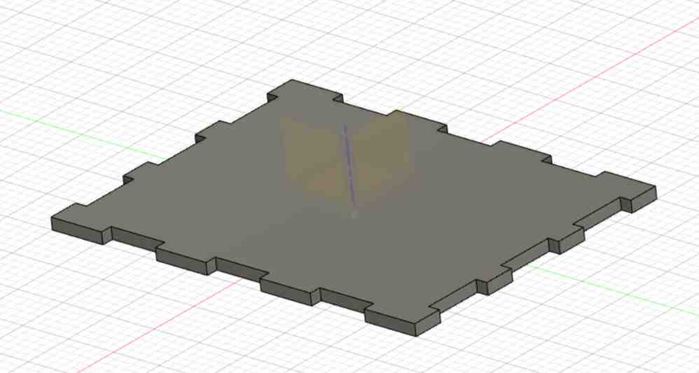
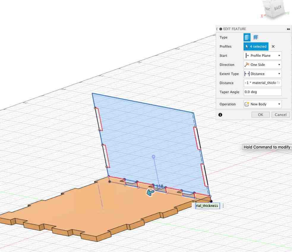
Now I had the base! Time to make a long side using the project function, drawing a rectangle, drawing the slots like before with the mirror function, and then extruding:
I then again used the mirror function to create the other long side. To get the short side, I used the project function so I could unclick the long side’s slots when extruding:
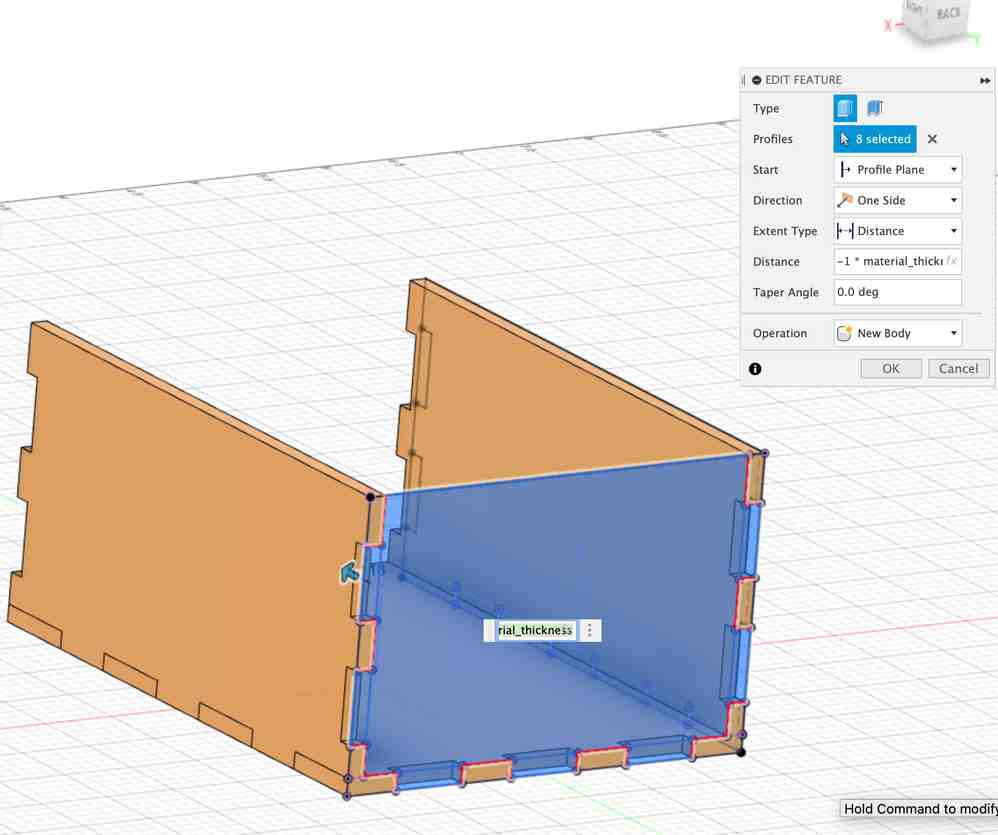
Note while extruding that I extrude a distance of the material (defined in user parameters). This is so that the corners will be flush and I can make this cut work for any type of material. I then went to Modify –> Combine to Select the short side as the target body and the other two sides as the tool body:
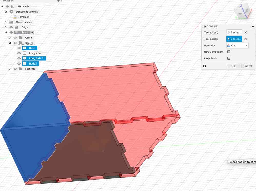
When combining, the target is where the changes will be applied, and the tool is the body that will do the changes. In a cut operation, you remove the overlap between the tool body and the target, from the target body. I did this so that there is no interference between the short side and the other two sides. Went ahead and did this again while making the base the target and the other two sides the tool bodies but I am not sure if this was necessary. I checked that there was no interference with Inspect –> Interference, selected all the sides, then hit compute. Then, I mirrored the short side to make another short side.
I then selected the long side, left clicked, and selected create sketch. Then, I exported the sketch as a dxf by right clicking on it.
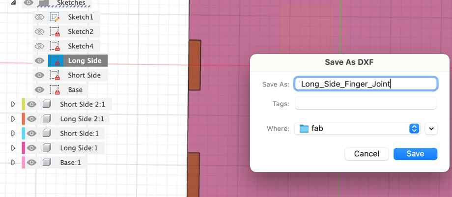
I repeated this for the short side and the base.
Cutting
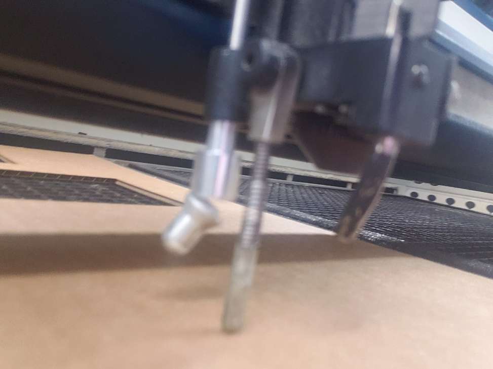
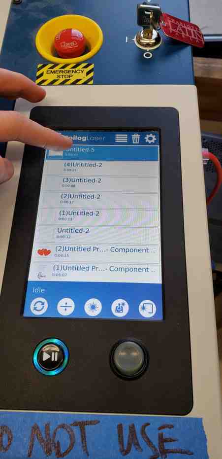
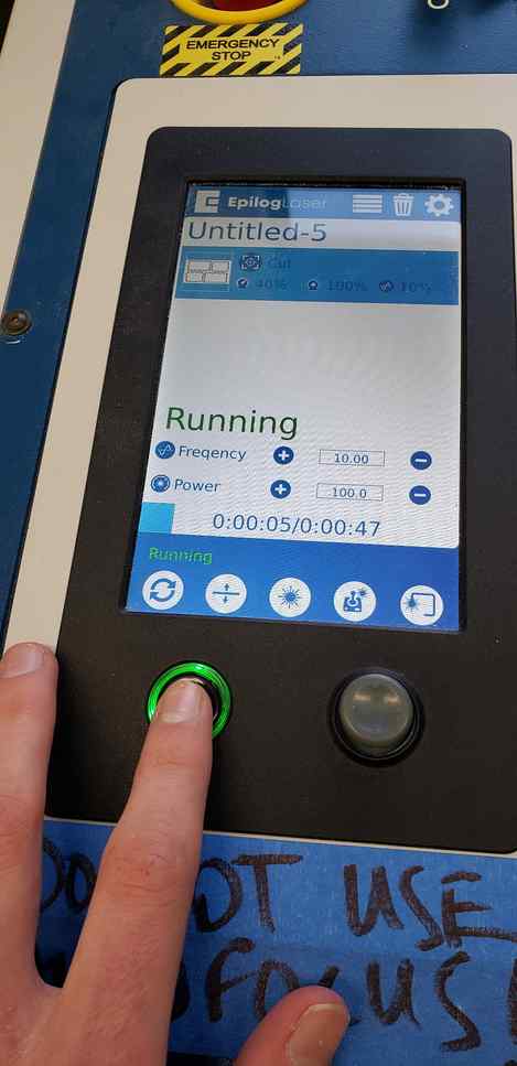
I always forget the steps to the laser cutter so here are them in pictures -
Use “Jogging” feature to move the cutter to the board you want to cut and use the focus gauge to focus the laser.
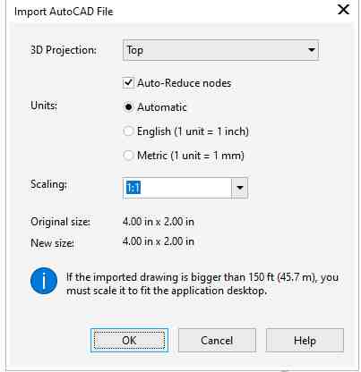
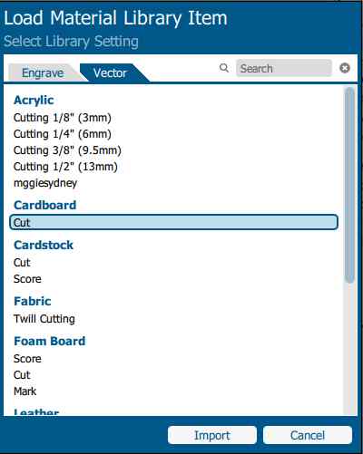
Upload the DXF File(s) in CorelDraw and print with the following settings:
My first attempt at cutting was a little cardboard version. The lab was closing so I did not have time to cut the base:
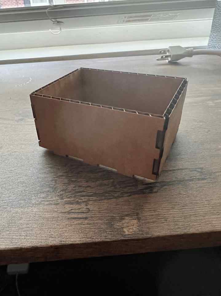
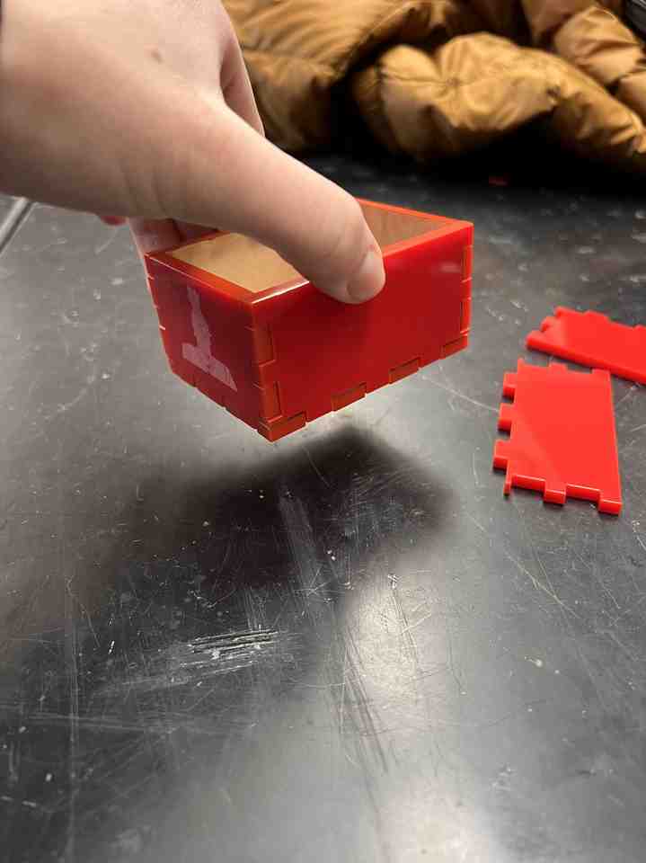
Though the base should help, the slots seem an ounce too big on the long side for the short side’s arms. I decided to try my next cut with a depth of 3 in, not 4 in, to prove this design is parametric and to use acrylic as opposed to cardboard - so I also had to edit the material thickness parameter. Unfortunately, the sides were a little loose again. So I made the slots tighter by the size of the kerf (0.01) in the sketch using the line funciton. It was easiest to make the slots tighter by a large number like 0.1 so that I could see the sections added and then make the dimension kerf/2 after the fact.
After doing this I could pick up the box without anything coming loose:
My Corel Draw file is linked here and my fusion360 file is linked here.