12. Machine Design: Bit Checkout Machine
This week I worked on the electronics portion of our group’s machine - a bit checkout system. In the past, Charlotte Latin has had some problems with people not putting bits back in their rightful place. As a result, there have been numerous bits left out or lost :(
See our group page here for the design of the machine. All code is shown below or can be downloaded here - master arduino code and slave arduino code.
Components
The following components were used for the UI electronics portion:
1) Sparkfun 16x2 LCD Screen 2) 2x Limit Switches 3) Rotary Encoder 4) 2 Arduino Unos (Note: One Arduino controls the lcd screen and the other controls the stepper and listens to commands from the first arduino like when to start and stop)
I wrote the code for the stepper motor, but I did not have part in the wiring of the stepper motor. See Barbara Morrow’s page for info on that.
The pinout chart for the Arduino controlling the LCD is shown below:
  LCD
  ----
  Pin 1 on the LCD is the one closest to the corner.
  Start there and work your way up.

  1 to GND
  2 to 5V
  3 to the 10K resistor, which is connected to ground
  4 to Arduino digital pin 12
  5 to GND
  6 to Arduino digital pin 11
  7 (no connection)
  8 (no connection)
  9 (no connection)
  10 (no connection)
  11 to Arduino  digital pin 5
  12 to Arduino  digital pin 4
  13 to Arduino  digital pin 9
  14 to Arduino  digital pin 8
  15 to 5V
  16 to GND


  Rotary Encoder Pinouts (I don't think there is an necessary orientation?):
  -----------------------

  Three pin Side:
  1 to digital pin 3
  2 to GND
  3 to digital pin 2

  Two pin side-
  1 to digital pin 13
  2 to digital pin 7, also 560 Ohm resistor connected to ground

Limit Pin Door
--------------
V to 5V
S to digital pin 6
G to GND

Limit Pin Home
---------------
V to 5V
S to digital pin 10
G to GND

I2C Bus Slave Board Connection
-------------------------------
A4 to other Slave Arduino's A4
A5 to Slave Arduino's A5
Slave GND must be connected to Master GND
How the UI works:
1) The User will see “Enter Position:” on the LCD screen 2) The User will turn the encoder to until the correct position (1-30) is shown on the LCD screen 3) The User will be asked if the position they chose is the position they intended to choose or if they would like to go back (had to add because it happened to me a few times). The user will push down on the encoder if it is the position they intended. 4) The User will be shown “Click to confirm you will scan bit after wheel moves.” and will click down on the encoder to proceed 5) The Stepper will move to desired location 6) The student will scan the bit, open the door, grab the bit, close the door 7) The Stepper will move back to home as soon as the student closes the door (because the limit Switch on the door is triggered) 8) The screen will be ready for a new user when the stepper has returned home, as triggered by the limit switch at the home position.
LCD Pinout
We found a sparkfun LCD screen in our lab so we thought that would be a fun addition to the UI experience. This LCD is only 16x2 (i.e. can only show 32 characters at once) but boy did it require an infinite number of wires. I hooked up the LCD according to this image below I found online:
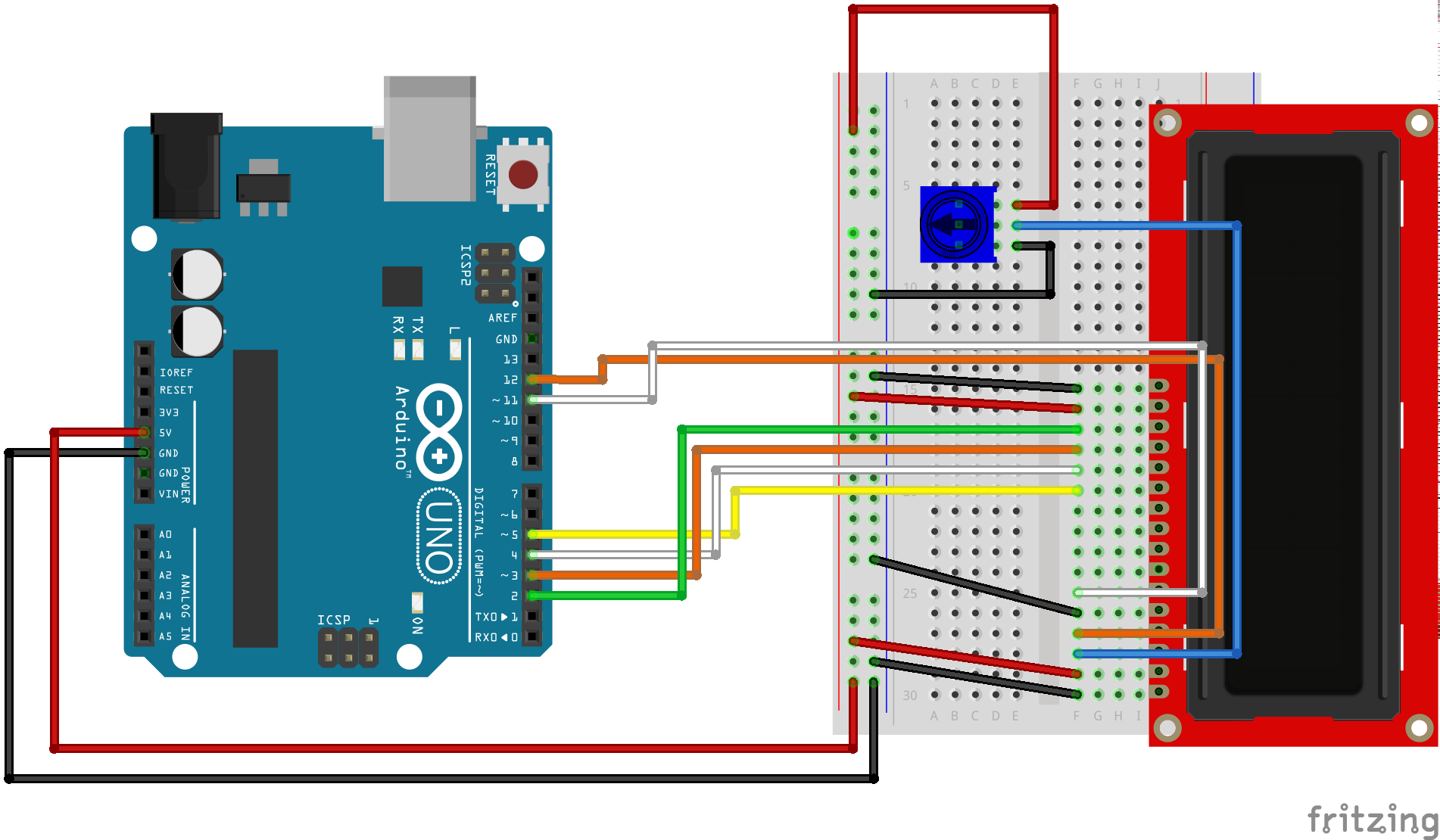
However, I did not have a potentiometer on hand like the picture shows. In addition, the potentiometer here is just for adjusting the contrast, and in reality, once we like how the screen’s contrast looks, we will not need to adjust it again. So, I found a random collection of 30+ resistors at my house and started trying different combinations on pin #3 (contrast pin ) of the lcd. Using a resistor-color lookup site, I found an estimate of each resistor’s value:
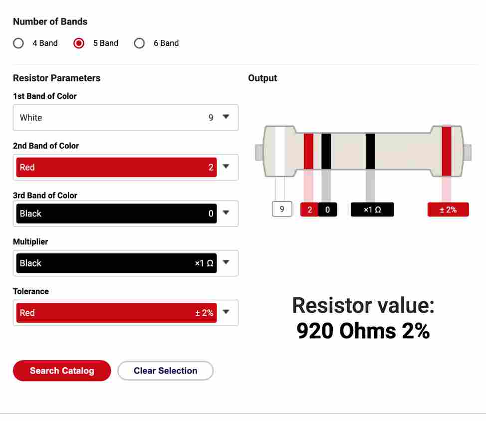
Using this site, I found that my “random” resistors added up to ~10K Ohms.
Rotary Encoder Pinout
My brother found an old rotary encoder:
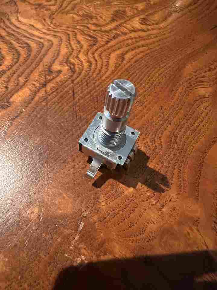
and we thought it’d be cool if the user used this to select the desired location. Since there are 30 bits, the user will scroll through 1-30 and press down on the encoder (since it is a button too) once the correct location is showing on the LCD screen.
The main problem I faced here was that none of the encoder’s pins were labeled. In addition, there wasn’t a part number or text on the encoder that I could lookup (I think they typically come with a breakout board where I can look up all that info). So, I was in the dark on how to connect the pinouts. This image from this site was helpful, though, I didn’t follow it exactly (See pinout list above to see exactly what I did).

The two revelations I had were:
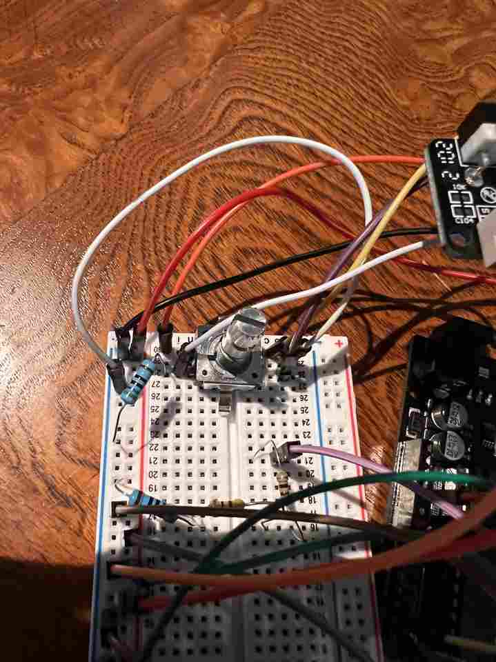
1) On the three-pin side of the encoder, the GND was in the middle of the 3 pins 2) On the two-pin side of the encoder, I needed a resistor also connected to GND on the GND pin.
I couldn’t scroll through numbers until I realized (1) and the button portion of the encoder wouldn’t work properly until I figured out (2). The button worked immediately when I used a 560 Ohm resistor for (2) and I still am not sure I understand why. You can see a closeup of the messy wiring below:
Limit Switches
Unlike the rotary encoder, the limit switches took 2 seconds to get working because the GND, VCC, and Switch (where digital pin is plugged into) is properly labeled:
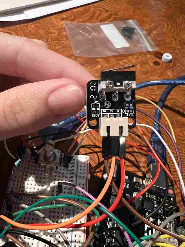
As explained above, two limit switched were used - one for showing that the door was open and another for showing that the stepper had returned home.
Talking between Arduinos
This was by FAR the toughest part. I had used all my Arduino’s digital pins for everything explained above but I still needed 4 more digital pins for the stepper. So, I needed to figure out how to make two arduinos talk. In hindsight, I could have just used the Arduino MEGA, but where is the fun in that?!
The reason this took longer than everything else was because I tried to follow these instructions at first. These instructions used digital pins 0 and 1 (TX and RX) for serial communication between the boards. I’m not sure why but when I couldn’t even send 0 and 1’s from one arduino to another after following these instructions. After multiple headaches, I decided there had to be a better way.
Alas, I found this link which uses I2C bus instead of RX and TX. The downside of this method is that one arduino is the master and one is the slave. The master (arduino controlling components explained above) can tell the slave (arduino controlling stepper) information but the slave cannot respond. Since I had limit switches that could tell the master when the stepper is home and when the door is closed, this wasn’t a huge deal. Really all I needed to do was import the Wire library, use the library’s commands explained in the link above, and make sure the two arduino’s A4, A5, and GND were connected. These instructions made it a piece of cake!
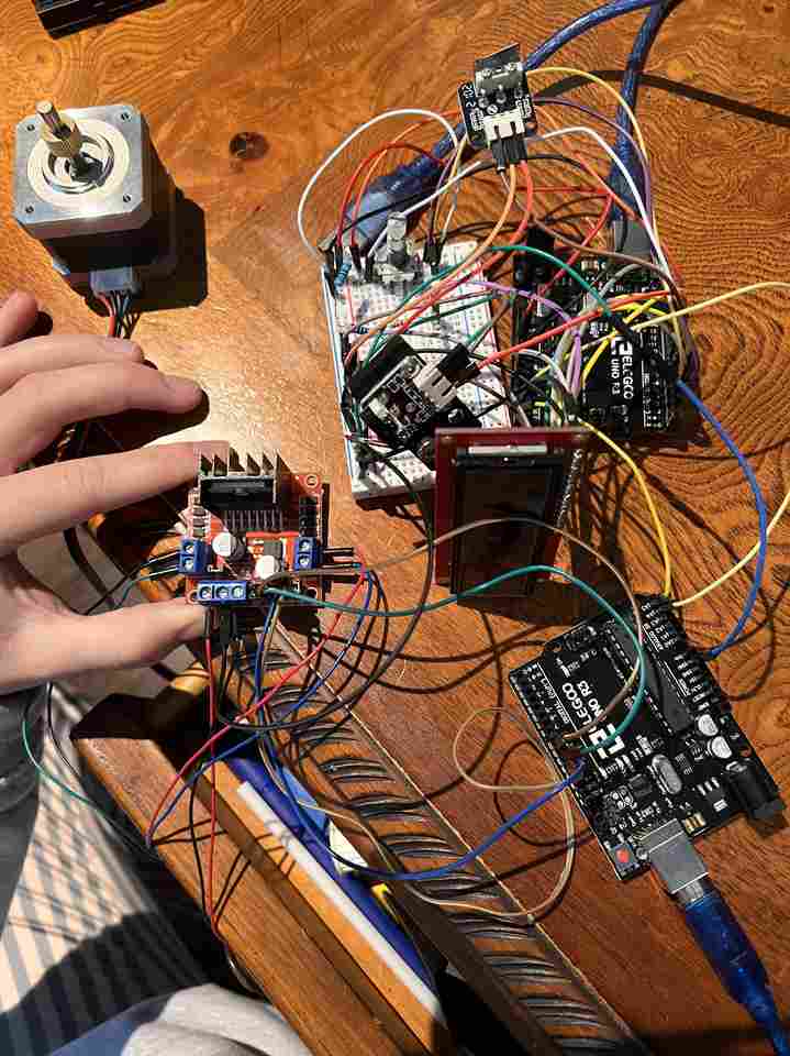
Entire Setup
Here is the horrifying final wiring of all the components:
As explained above, the code works as follows:
1) The User will see “Enter Position:” on the LCD screen 2) The User will turn the encoder to until the correct position (1-30) is shown on the LCD screen 3) The User will be asked if the position they chose is the position they intended to choose or if they would like to go back (had to add because it happened to me a few times). The user will push down on the encoder if it is the position they intended. 4) The User will be shown “Click to confirm you will scan bit after wheel moves.” and will click down on the encoder to proceed 5) The Stepper will move to desired location 6) The student will scan the bit, open the door, grab the bit, close the door 7) The Stepper will move back to home as soon as the student closes the door (because the limit Switch on the door is triggered) 8) The screen will be ready for a new user when the stepper has returned home, as triggered by the limit switch at the home position.
Here is a video showing this:
Master Code
#include <LiquidCrystal.h>
#include <Wire.h>

LiquidCrystal lcd(12,11,5,4,9,8); // Pins the LCD is using
static int encoderPinA = 2; // Our first hardware interrupt pin is digital pin 2
static int encoderPinB = 3; // Our second hardware interrupt pin is digital pin 3
static int limitPinHome = 10;
static int limitPinDoor = 6;
static int buttonPin = 13;
volatile byte aFlag = 0; // let's us know when we're expecting a rising edge on encoderPinA to signal that the encoder has arrived at a detent
volatile byte bFlag = 0; // let's us know when we're expecting a rising edge on encoderPinB to signal that the encoder has arrived at a detent (opposite direction to when aFlag is set)
volatile byte encoderPos = 0; //this variable stores our current value of encoder position. Change to int or uin16_t instead of byte if you want to record a larger range than 0-255
volatile byte oldEncPos = 0; //stores the last encoder position value so we can compare to the current reading and see if it has changed (so we know when to print to the serial monitor)
volatile byte reading = 0; //somewhere to store the direct values we read from our interrupt pins before checking to see if we have moved a whole detent

int desiredPos = 0;
bool b_selectedPos = 0;
String homeStr = "Enter Position:";
bool STEPPER_COMPLETE = 0;
int STEPPER_MSG = 0;
bool b_door_opened = 0;

void setup()
{
  Serial.begin(9600); // start the serial monitor link
  Wire.begin(); // To talk to Arduino #2 via I2C Bus

  // The LiquidCrystal library can be used with many different
  // LCD sizes. We're using one that's 2 lines of 16 characters,
  // so we'll inform the library of that:

  lcd.begin(16, 2);

  // Data sent to the display will stay there until it's
  // overwritten or power is removed. This can be a problem
  // when you upload a new sketch to the Arduino but old data
  // remains on the display. Let's clear the LCD using the
  // clear() command from the LiquidCrystal library:

  lcd.clear();

  lcd.print(homeStr);
  lcd.setCursor(0,1); // Set cursor to column 0, line 1 (2nd row)
  lcd.print("HOME");

  pinMode(buttonPin, OUTPUT);
  digitalWrite(buttonPin, HIGH);
  pinMode(encoderPinA, INPUT_PULLUP); // set encoderPinA as an input, pulled HIGH to the logic voltage (5V or 3.3V for most cases)
  pinMode(encoderPinB, INPUT_PULLUP); // set encoderPinB as an input, pulled HIGH to the logic voltage (5V or 3.3V for most cases)
  attachInterrupt(0,EncoderPinA,RISING); // set an interrupt on PinA, looking for a rising edge signal and executing the "PinA" Interrupt Service Routine (below)
  attachInterrupt(1,EncoderPinB,RISING); // set an interrupt on PinB, looking for a rising edge signal and executing the "PinB" Interrupt Service Routine (below)

}

void EncoderPinA(){
  cli(); //stop interrupts happening before we read pin values
  reading = PIND & 0xC; // read all eight pin values then strip away all but encoderPinA and encoderPinB's values
  if(reading == B00001100 && aFlag) { //check that we have both pins at detent (HIGH) and that we are expecting detent on this pin's rising edge
    encoderPos --; //decrement the encoder's position count
    bFlag = 0; //reset flags for the next turn
    aFlag = 0; //reset flags for the next turn
  }
  else if (reading == B00000100) bFlag = 1; //signal that we're expecting encoderPinB to signal the transition to detent from free rotation
  sei(); //restart interrupts
}

void EncoderPinB(){
  cli(); //stop interrupts happening before we read pin values
  reading = PIND & 0xC; //read all eight pin values then strip away all but encoderPinA and encoderPinB's values
  if (reading == B00001100 && bFlag) { //check that we have both pins at detent (HIGH) and that we are expecting detent on this pin's rising edge
    encoderPos ++; //increment the encoder's position count
    bFlag = 0; //reset flags for the next turn
    aFlag = 0; //reset flags for the next turn
  }
  else if (reading == B00001000) aFlag = 1; //signal that we're expecting encoderPinA to signal the transition to detent from free rotation
  sei(); //restart interrupts
}

void confirmDesiredPos(int desired_pos) {
  bool b_optionSelected = 0;
  delay(1000); // must add delay after every selection or logic doesn't work
  lcd.clear();
  lcd.print("Pos " + (String) desired_pos + " selected:");
  lcd.setCursor(0,1);
  lcd.print("      ");

  while (!b_optionSelected) {
    int contButtonState = digitalRead(7);
    lcd.setCursor(0,1);
    if ((encoderPos % 2) == 0) {
      lcd.print("Continue");
      if (contButtonState == HIGH) {
        b_selectedPos = 1;
        desiredPos = desired_pos;
        b_optionSelected = 1;
        delay(1000);

      }
    } else {
      lcd.print("Go Back ");
      if (contButtonState == HIGH) {
         lcd.clear();
         lcd.print(homeStr);
         b_optionSelected = 1;
         delay(1000);
      }
    }
  }
}

void studentAuthorization() {
  delay(1000);
  bool b_bitChecked = 0;
  String authStr = "Click to confirm you will scan  bit after wheel moves.";


  while (!b_bitChecked) {
    lcd.clear(); lcd.setCursor(0,0);
    lcd.print(authStr.substring(0,16));
    lcd.setCursor(0,1);
    lcd.print(authStr.substring(17,32));

    // Have to use timer here while displaying msg instead of delay so you can still read incoming button state
    int contButtonState = LOW;
    long time1 = millis();
    long time2 = millis();
    while (time2 - time1 < 2000 & contButtonState == LOW) {
      contButtonState = digitalRead(7);
      time2 = millis();
    }

    lcd.clear(); lcd.setCursor(0,0);
    lcd.print(authStr.substring(32, 47));
    lcd.setCursor(0,1);
    lcd.print(authStr.substring(47, authStr.length()));

    time1 = millis();
    while (time2 - time1 < 2000 & contButtonState == LOW) {
      contButtonState = digitalRead(7);
      time2 = millis();
      Serial.println(time2 - time1);
    }

    if (contButtonState == HIGH) {
      b_selectedPos = 1;
      b_bitChecked = 1;
      delay(1000);
    }
  }
}

int checkEncoderPosition(){
  if(!b_selectedPos & oldEncPos != encoderPos) {
    //Serial.println(encoderPos);
    lcd.print("       "); // Erase the largest possible number
    lcd.setCursor(0,1);
    //lcd.print(int (encoderPos*30/256)); // Map values between 0-30 as opposed to 0-255
    lcd.print(encoderPos);
    oldEncPos = encoderPos;
  }
}


void loop()
{

  checkEncoderPosition();
  int buttonState = digitalRead(7);

  if (buttonState == HIGH) { // if position selected
    confirmDesiredPos(encoderPos); // confirm this is the actual position they wanted

  }

  if (b_selectedPos == 1) { // if user confirmed position is correct
    studentAuthorization(); // verify that they have used the checkout system
    // Function: Send to Stepper
    lcd.clear();
    lcd.print("Moving... ");


    while (!STEPPER_COMPLETE) {
     if (b_door_opened == 0) {
          STEPPER_MSG = (int) desiredPos; // Send desired position
          Wire.beginTransmission(9); // transmit to device #9
          Wire.write(STEPPER_MSG); // Tell Stepper to Start
          Wire.endTransmission();    // stop transmitting

     }
      if (digitalRead(limitPinDoor) == 1) {
            lcd.setCursor(0,0);
            lcd.print("Door Opened");
            b_door_opened = 1;

            // if (digitalRead(limitPinDoor == 0)) {
            //  Wire.write(
            // }
      }


      else if (digitalRead(limitPinHome) == 0 and b_door_opened == 1) {

        STEPPER_COMPLETE = 1;
        // Wire.write(-1); // -1 Message Tells the Stepper it is home.

      }  else if (digitalRead(limitPinDoor) == 0 & b_door_opened == 1) {
         lcd.setCursor(0,0);
         lcd.print("Returning Home... ");
         Wire.beginTransmission(9); // transmit to device #9
         Wire.write(0); // 0 Tells stepper to turn left until it is home
         Wire.endTransmission();    // stop transmitting
      }
    }

   STEPPER_COMPLETE = 0;
   b_selectedPos = 0;
   b_door_opened = 0;
   lcd.clear();

   lcd.print(homeStr);


  }

}
Slave Code (Separate File)
#include <Wire.h>
#include <Stepper.h>

// STEPPER_MSG Directions Received From Wire:
// Values 1-30: Go to Position
// Value -1: Turn Left
// Value 0: Stay Put

//Stepper Motor 1
int STEPPER_MSG;
int PREV_MSG;
int MSG;
int POSITION;
const int stepsPerRevolution = 200;
Stepper myStepper(stepsPerRevolution, 8, 9, 10, 11);

void setup(){
  Wire.begin(9); // Start I2C Bus as Slave on Address 9
  Wire.onReceive(receiveEvent);
  Serial.begin(9600);


  myStepper.setSpeed(60);
}

void receiveEvent(int bytes) {
  STEPPER_MSG = Wire.read();    // read one character from the I2C

}

int steps = 0;

void loop(){
  Serial.println(STEPPER_MSG);

  int GEAR_RATIO = 20;
  int STEPS_TOTAL = STEPPER_MSG * GEAR_RATIO;
  Serial.println("STEPS_TOTAL: " + (String) STEPS_TOTAL);


  while (STEPPER_MSG > 0 & steps <= STEPS_TOTAL) {
    Serial.println("Steps done: " + steps);
    steps++;
    myStepper.step(1);
    delay(20);
    // Once you Get to position, stay
   }

   //if (STEPPER_MSG  0 | steps == STEPS_TOTAL) {
   // steps = 0;
   //}

  while (STEPPER_MSG == 0 & steps >= 0) {
    myStepper.step(-1);
    steps--;
    delay(20);
  }


}