11. Output devices
See group work here. In our group work, I learned that power is directly related to voltage and current and as current and voltage increase, power also increases. However, power will increase at a faster rate than the amount that current and voltage are increased. This confirms the P=I^2V formula.
The code is shown below.
This week I decided to really dig into the conveyor belt portion of my final project. The output I decided to use was FITEC’s FS90R servo:
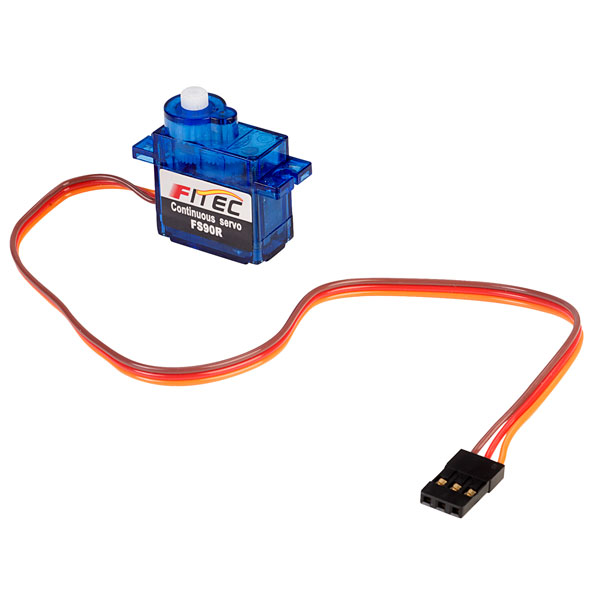
These servos will be used to spin the football while finding the laces and also used for moving the football up the conveyor belt. For spinning the football, I will use this wheel:
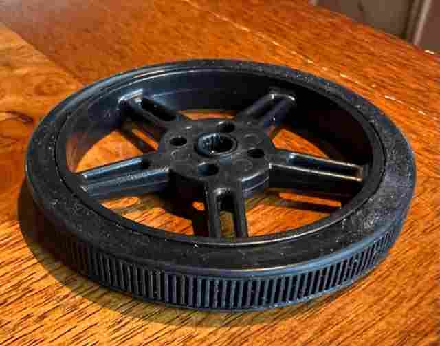
For moving the football up the conveyor belt I will use two servos to drive a pulley system.
First, I wanted to make sure I could turn on the servo with my arduino.
Using this code:
/* Sweep
 by BARRAGAN <http://barraganstudio.com>
 This example code is in the public domain.

 modified 8 Nov 2013
 by Scott Fitzgerald
 https://www.arduino.cc/en/Tutorial/LibraryExamples/Sweep
*/

#include <Servo.h>

Servo myservo;  // create servo object to control a servo
// twelve servo objects can be created on most boards

int pos = 0;    // variable to store the servo position

void setup() {
  myservo.attach(9);  // attaches the servo on pin 9 to the servo object
}

void loop() {
  for (pos = 0; pos <= 180; pos += 1) { // goes from 0 degrees to 180 degrees
    // in steps of 1 degree
    myservo.write(pos);              // tell servo to go to position in variable 'pos'
    delay(15);                       // waits 15 ms for the servo to reach the position
  }
  for (pos = 180; pos >= 0; pos -= 1) { // goes from 180 degrees to 0 degrees
    myservo.write(pos);              // tell servo to go to position in variable 'pos'
    delay(15);                       // waits 15 ms for the servo to reach the position
  }
}
and plugging the orange wire into A0, the red wire into 5V and the brown wire into GND on my Arduino, I was able to turn see the servo rotate clockwise and then counterclockwise repeatedly.
Custom Board
For this week, I was hoping to design and mill my circuit board that will be used for the conveyor belt portion of my final project. This circuit board will need to power and instruct a ESP32-CAM, two groups of servos, and one HC-SR04 sensor. Because I want to power so many components, I needed a chip with enough digital output pins that support PWM (for servo and HC-SR04 sensor) - and so I chose the ATTiny1614 chip. The datasheet for this chip is shown below:
My initial design in KiCAD for my custom board is shown below:
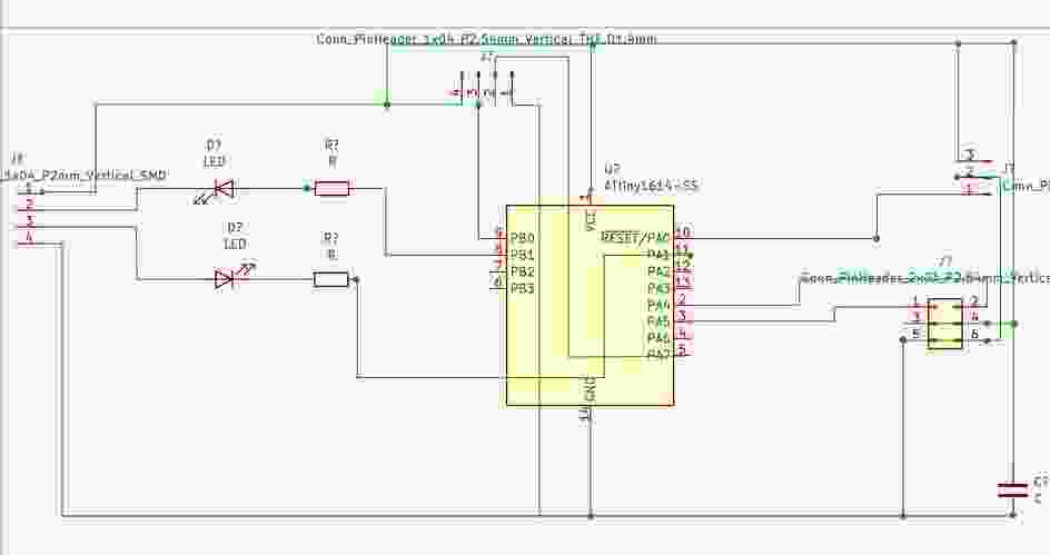
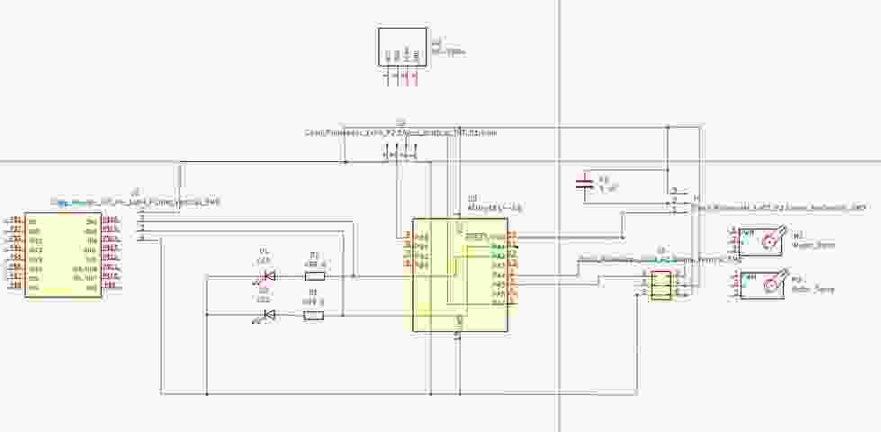
After talking to Dr. Harris, he suggested that I connect the LEDs to ground so that if one isn’t working the communication is not completely cut off. Below shows my updated board:
Together, Dr. Harris and I also contemplated a few other issues with milling my final board now:
1) I could potentially communicate wirelessly between the ESP32 and my board 2) I may end up needing a beefier servo, or may want to switch out the servo with a stepper motor 3) The final location of each component isn’t known yet, so I may not want each component controlled by the same board
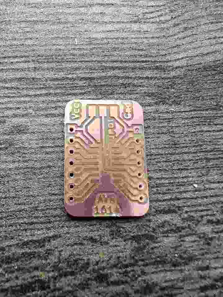
So, instead of milling my final board now, my brother had the bright idea to mill a breakout board for the ATTiny1614 that I would use, wire this circuit above on a breadboard, and then make adjustments as they come up. This seemed to be the most logical solution to save me some time and effort, which we all know fab academy can drain both of those vital resources. Below is the breakout board for the ATTiny1614 that my brother and I are both using for our projects:
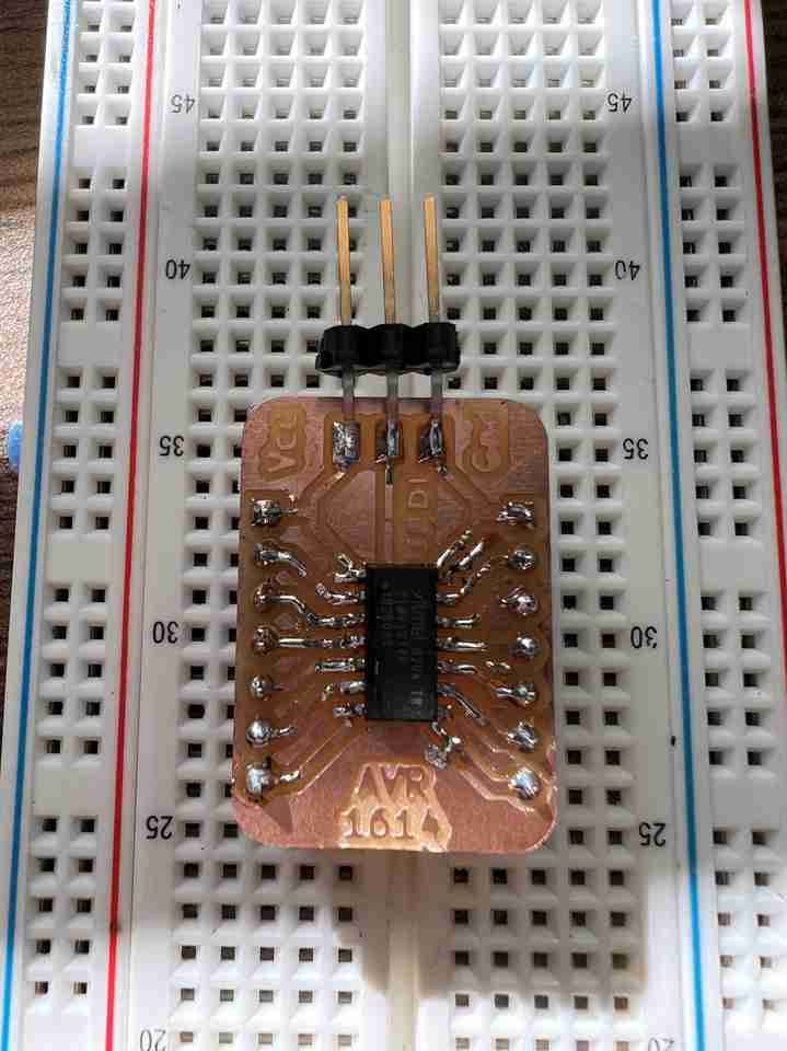
And with the 1614 soldered on:
See my Electronics Production work for a more detailed description of how to program a chip. To summarize, my general workflow is:
- Load jtag2updi.ino onto the Arduino Uno
- Connect the 1614’s UPDI pin to Arduino’s pin 6 (I put a 4.7K Ohm resistor in between but I’m not sure if this is necessary)
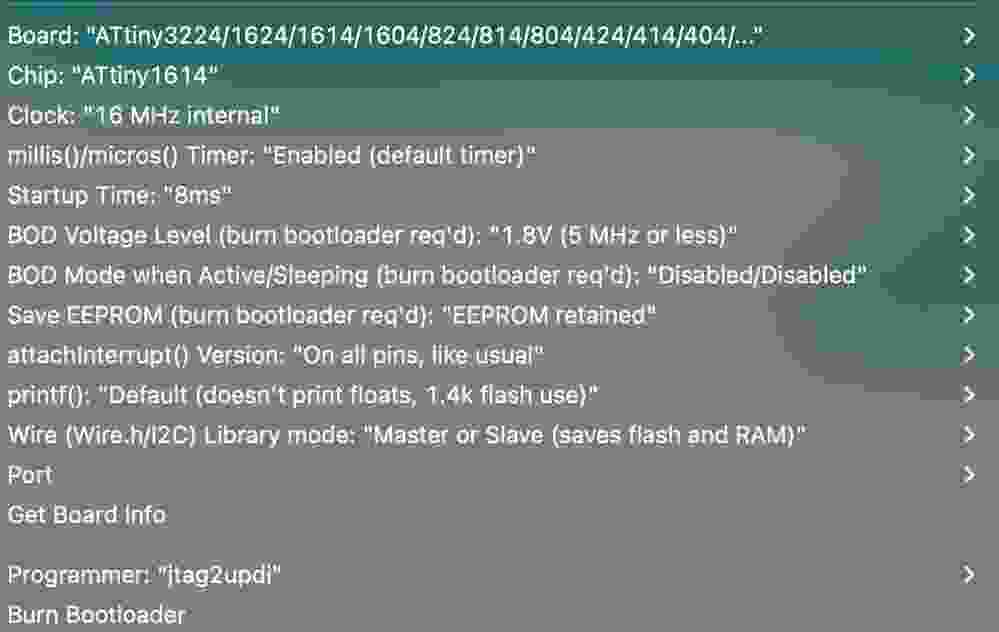
- Load whichever code you want the chip to run onto the 1614 using jtag2updi as the Programmer, and the ATTiny1614 chip as the processor. My code loaded using both 16MHz and 20MHz so I am not sure that setting is important. I did not change any other default setting:
I completed this step after Inputs Week so I chose to run my output, a FS90R servo, after an object was detected within 8cm by the HRS04 sensor. The code I loaded on the 1614 chip is shown below (Note I had to switch the Trig pin from pin 7 shown in the diagram above to pin 1 because I accidentally ripped the traces on the right hand side of the breakout board):
/* Example code for HC-SR04 ultrasonic distance sensor with Arduino. No library required. More info: https://www.makerguides.com */
#include <Servo.h>
// Define Trig and Echo pin:
#define trigPin 1
#define echoPin 3

#define MAX_PWM 2150
#define MID_PWM 1500
#define MIN_PWM 850

int pos = 0;
Servo myservo;

// Define variables:
long duration;
int distance;

void setup() {
  // Define inputs and outputs:
  pinMode(trigPin, OUTPUT);
  pinMode(echoPin, INPUT);
  myservo.attach(0); //attaches the servo on pin 0
  //inMode(pin, OUTPUT);

  //Begin Serial communication at a baudrate of 9600:
  Serial.begin(9600);
  Serial.print("Distance = ");
}

void loop() {
  // Clear the trigPin by setting it LOW:
  digitalWrite(trigPin, LOW);
  delayMicroseconds(5);

  // Trigger the sensor by setting the trigPin high for 10 microseconds:
  digitalWrite(trigPin, HIGH);
  delayMicroseconds(10);
  digitalWrite(trigPin, LOW);

  // Read the echoPin, pulseIn() returns the duration (length of the pulse) in microseconds:
  duration = pulseIn(echoPin, HIGH);
  // Calculate the distance:
  distance = duration * 0.034 / 2;
  if (distance <= 8) {
    myservo.write(1600);
  } else {
      //digitalWrite(pin, LOW);
    myservo.write(1500);
  }

  // Print the distance on the Serial Monitor (Ctrl+Shift+M):
  Serial.print("Distance = ");
  Serial.print(distance);
  Serial.println(" cm");

  delay(50);

}
The key code for the output device is:
#include <Servo.h>#define MAX_PWM 2150,#define MID_PWM 1500,#define MIN_PWM 850myservo.attach(0); //attaches the servo on pin 0myservo.write(1600);myservo.write(MID_PWM);
Using 1600 within myservo.write() spins the servo while 1500 (MID_PWM) makes the servo stop. This was the biggest challenge in this week’s assignment because defining the max, mid, and min PWM appears to be specific to continuous servos, which the FS90R is. Most servo code on the internet are for servos that can only go 180 degrees (as the first code attached above shows). This link is the link that helped me discover this.
Below is a video of the servo moving and stopping when an object is within 8cm:
For my final project I may end up needing a beefier servo or stepper, but I’ll cross that bridge when I get there.