8. Computer controlled machining
See here to download the fusion360 design and here to download the aspire design. See here for our group project work.
Safety and Workflow
We began this week learning safety tips and tricks to using our ShopBot machine. Here is a general rundown:
In addition, the troubleshooting manual can be found here.
Designing a Cup Table in Fusion360
Below shows my first attempt at a design:
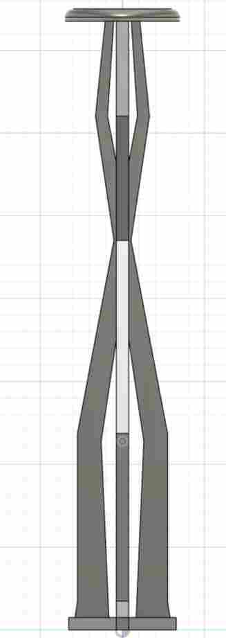
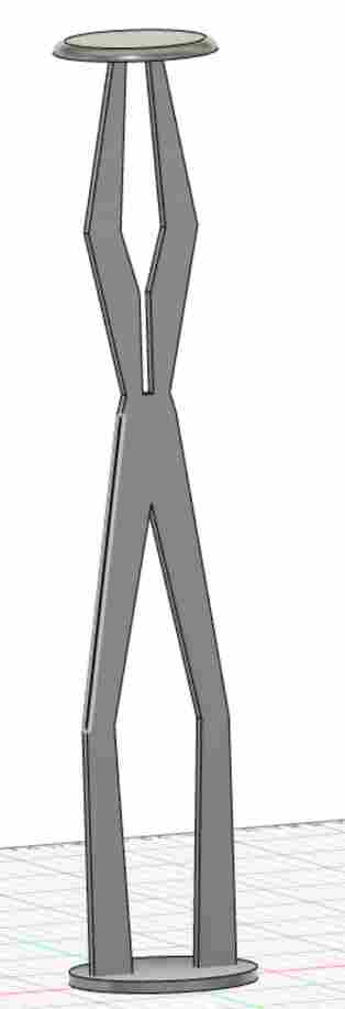
And with the Extrude, Copy, and Rotate commands I ended up with this:
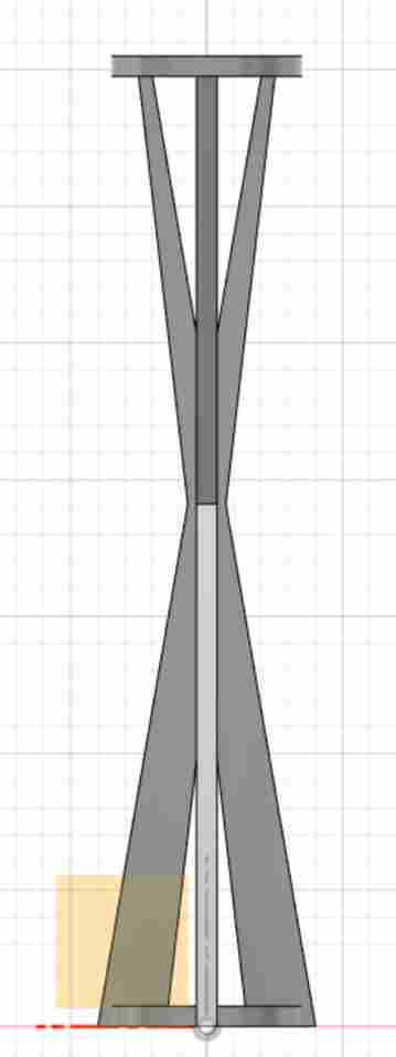
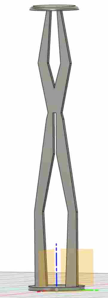
BUT, I don’t know…I thought this looked kind of boring so I decided to make it a little funkier:
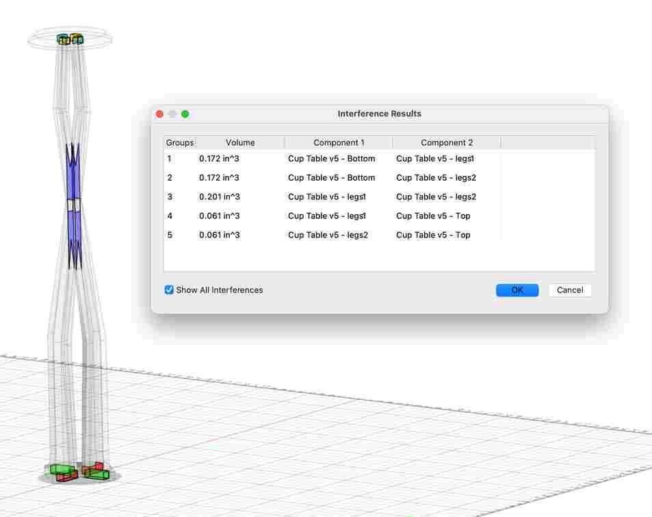
I projected each of the legs onto the XZ and YZ axis, found their interferences and extrude-cut push-in slots for the legs to connect. One problem that I kept running into was that my projections were projecting onto a surface rather than the desired XZ/XY plane:
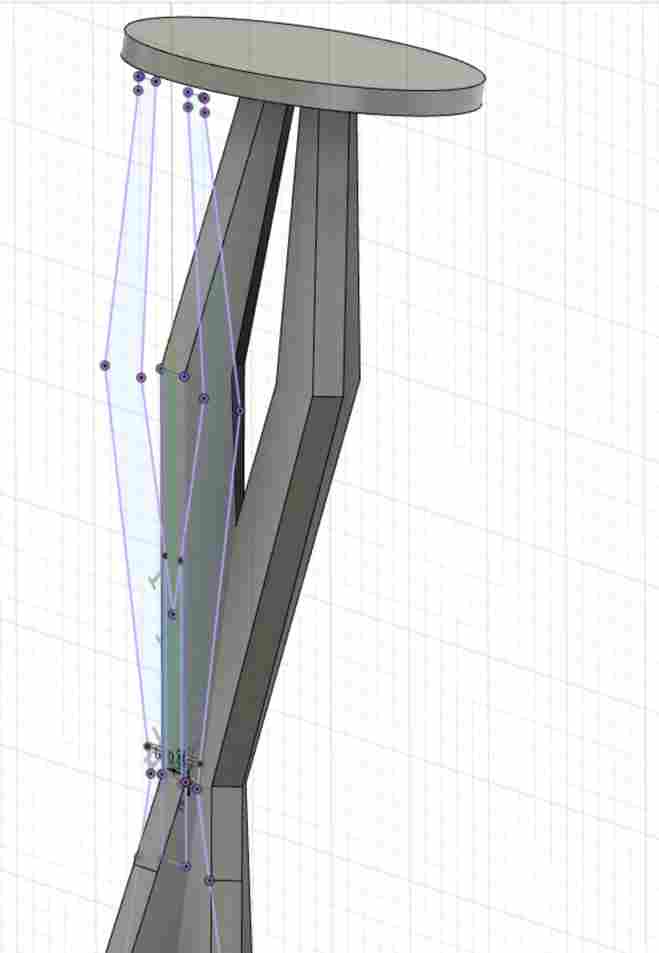
Charlie Horvath, my bright brother, showed me a neat technique - right clicking on a sketch icon and clicking “Redefine Sketch Plane” and proceeding to hit the XZ or YZ under the origin section will fix this problem. After being able to project correctly, I discovered extrude cut at each of the interferences:
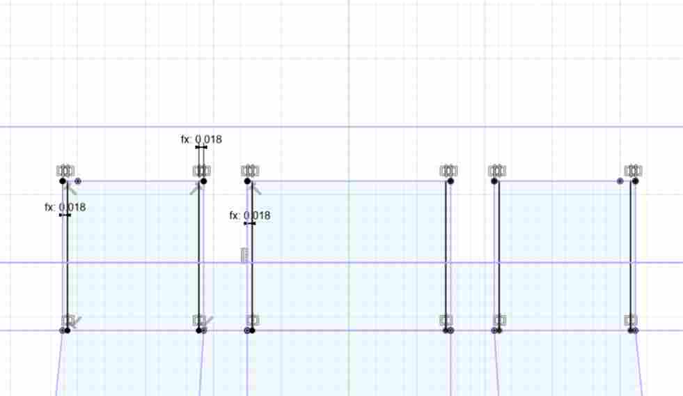
We have a nifty tool at Charlotte Latin that will tell you how wide you want your slots:
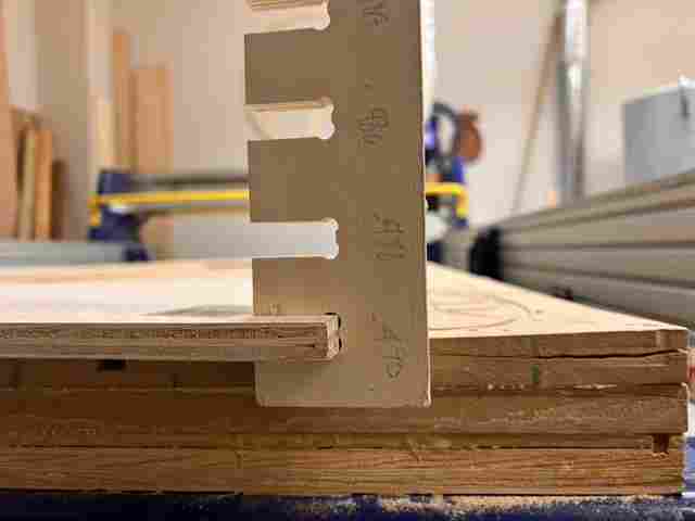
So instead of making the slots the material thickness, instead I made it this desired slot thickness:

And did the same for the other set of legs:
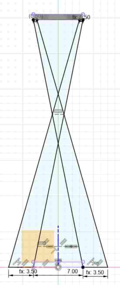
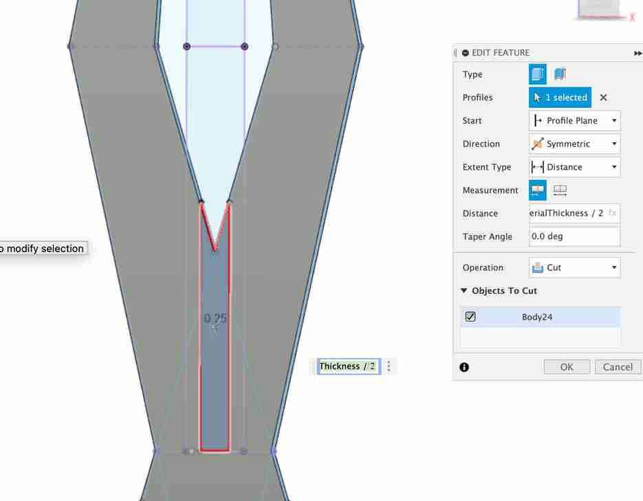
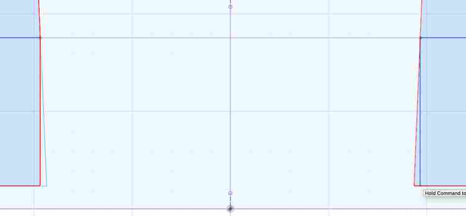
Similarily, I extrude cut the slots in the top and bottom of the table. However, I thought it may be hard to CNC cut slanted slots, which naturally the extrude cut by the angled legs created, so I made sure each slot in the top and bottom were vertical. The picture below is the sketch of the slots on the bottom of the table. The right hand side shows the slant that would be difficult to cut while the left hand side shows the straight edge that I created:
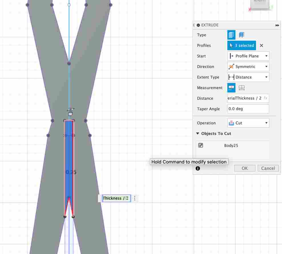
I also did this for the top of the table:
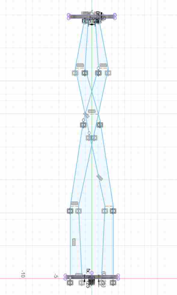
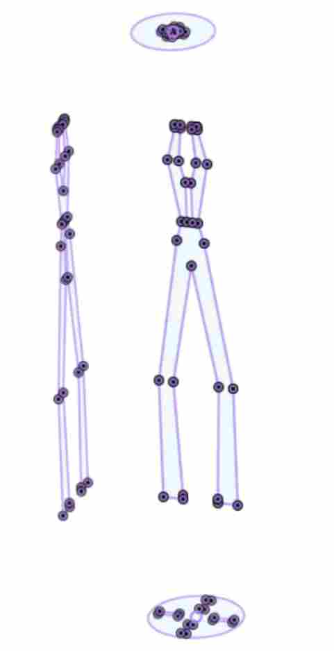
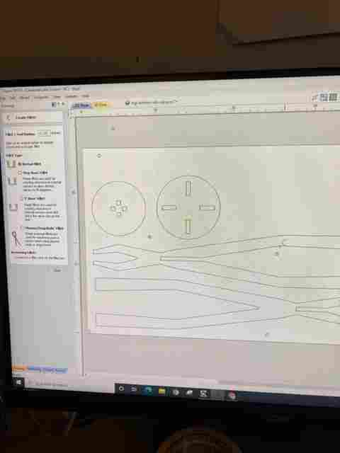
And then by creating offset planes and projecting the bodies onto them, I was able to turn my 3D design into 2D:
and then exported them as SVGs in Fusion360.
Aspire and ShopBot
Then, I opened the svgs in Aspire.
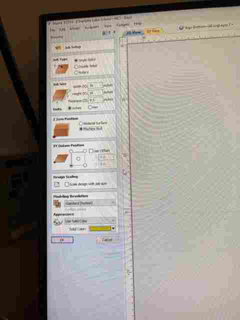
First, in Aspire, I changed the Job Setup settings to those that are listed below. The most important parts are making sure the material thickness is correct and the z zero position is from the bed, not the surface.
Before editing the Aspire file, we followed the steps in the document linked above for zeroing the z-axis using Latin’s nifty puck tool:
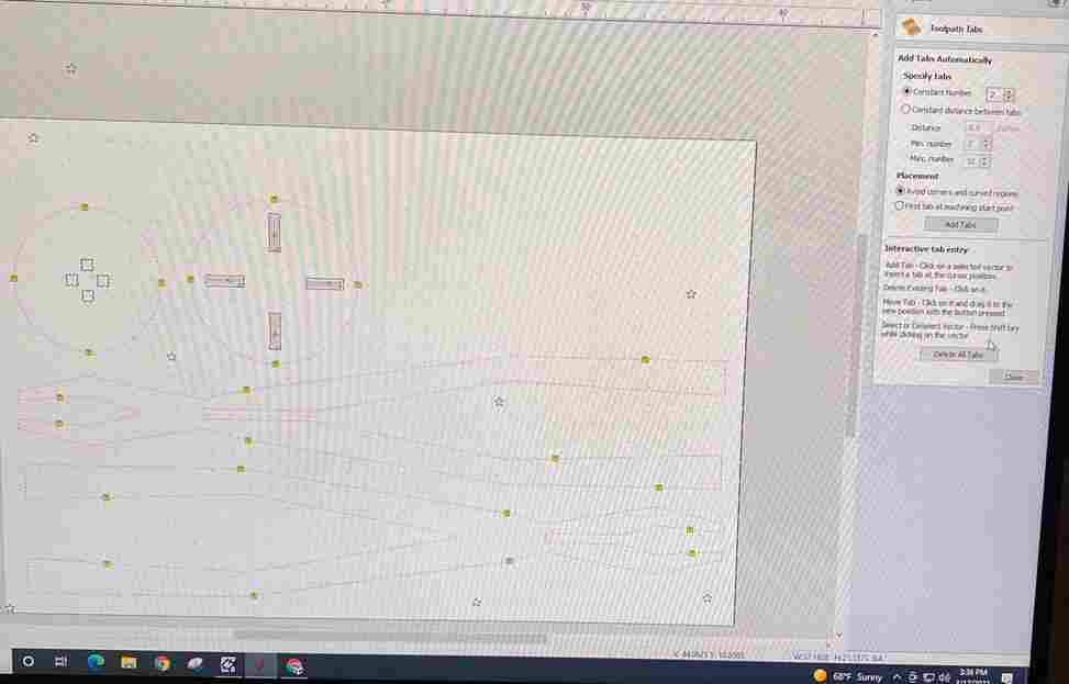
Then, I put the 0.5 inch board on the bed that I was planning to cut and drilled screws in to hold the board down to the bed. The location of these screws are denoted by stars below:
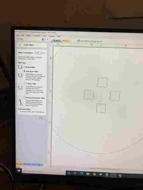
I then made all the internal corners dogbone-shaped:
and added tabs in to hold the table down as it is being cut:
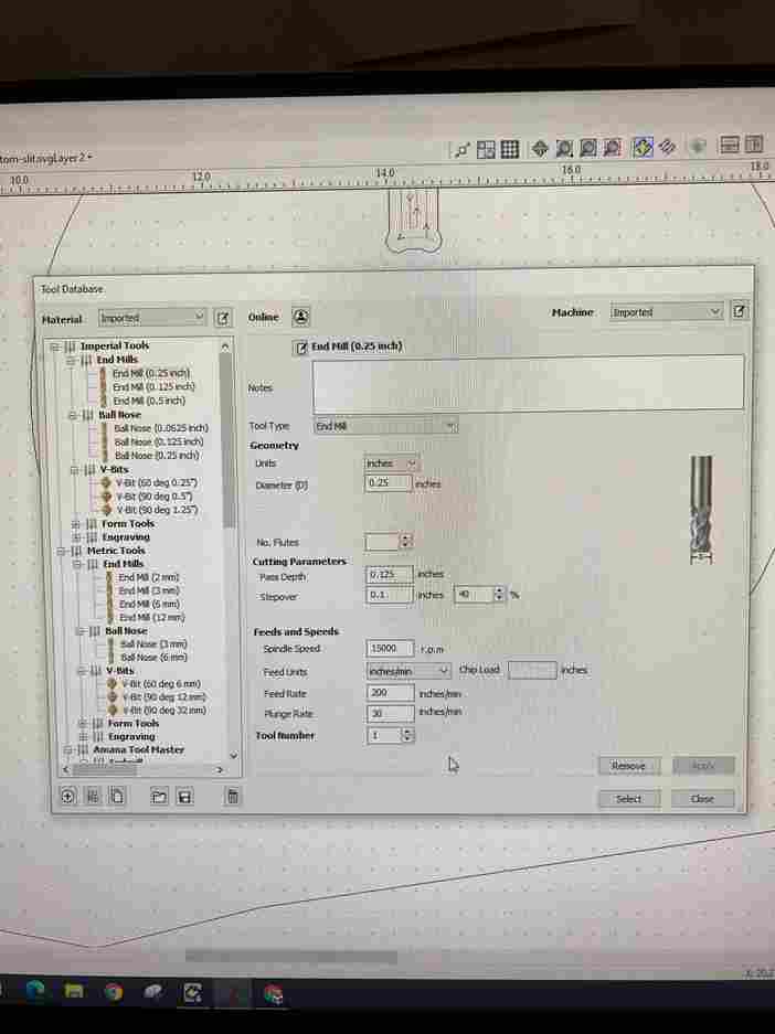
Made sure my bit size was correct (0.125):
And once all the settings were correct, I did an air test run. The key here is to change the offset to 1:
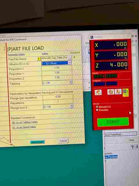
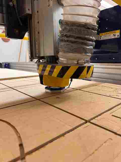
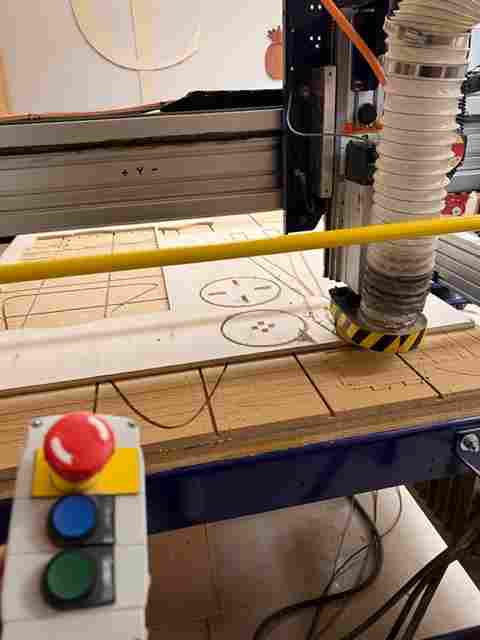
And since it didn’t look like it would hit any screws in the air test, I started cutting!
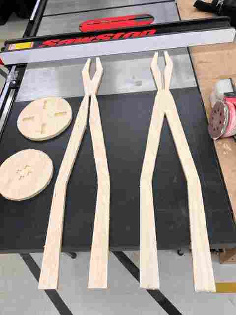
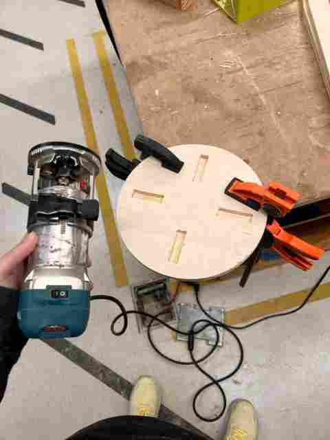
And then sanded everything using some fancy sanding machine tool. In addition, to give the top and bottom a fillet (you can see end result in the hero shot), I used this handheld cutting machine:
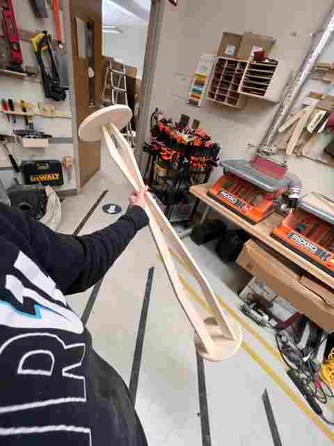
And without any glue or screws, the legs fit right in! Other kids seemed to struggle with the joints but I think the key is to make your design parametric, measure the material thickness before and change the design accordingly, and then to make sure the slot width is equal to the leg width (others were trying a smaller slot than leg to ensure a snug fit).
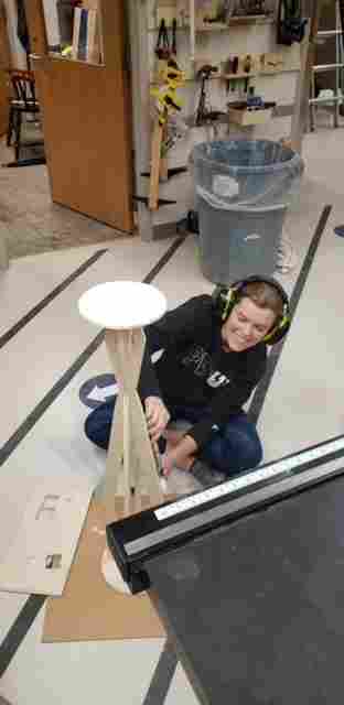
And not only did the legs fit right in, but nothing fell apart when I twirled the table around!
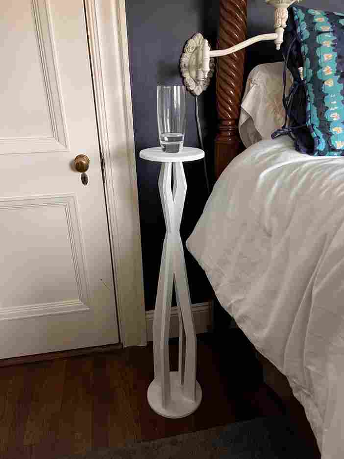
Then, I painted it:
and here it sits next to my bed today!