Group Assignment
Compare as many tool options as possible.
Individual Assignment
Write an application that interfaces a user with an input and or output device that you made.
Individual Assignment
Processing is a programming language designed for the visual arts community.
It is open source and uses basic syntax for creating drawings, animations, and interactive programs. It also includes a basic IDE, which serves as the programming interface.
Sketches are programs created in processing. They are uncompiled codes.
Some Processing commands
To run the sketch we use sketch-run command.
Sketch → Tweak command allows you to edit the program code in real-time as the sketch is running.
The Sketch → Present runs the sketch as a full-screen application.
I will test some of the sensors that I will be using in my final project and previously tested in Input Devices week.
Arduino and Processing IDE Communication
Arduino
First step we have to setup our program by writing the below code in Arduino.
We will start a serial communication from the Arduino at a baud rate of 9600.
Second step we are going to send data or a message from Arduino with a note telling it that every 100 milliseconds we need to send data.
Code:
Written by sparkfun
Modified by Ghinwa Azzi Fab Academy 2021
void setup()
  {
  Serial.begin(9600);
  }
void loop()
{

//send 'Hello, world!' over the serial port
Serial.println("Hello, world!");
//wait 100 milliseconds so we don't drive ourselves crazy
delay(100);
}
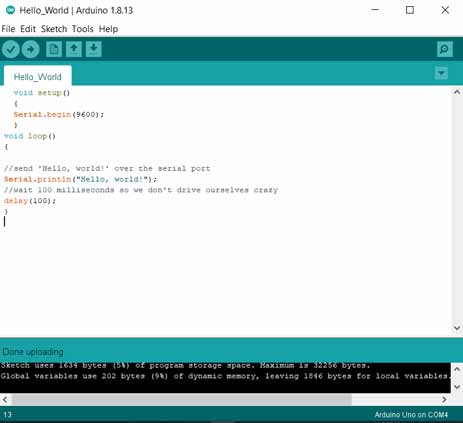
Then we will upload the code to the Arduino UNO board.
Processing
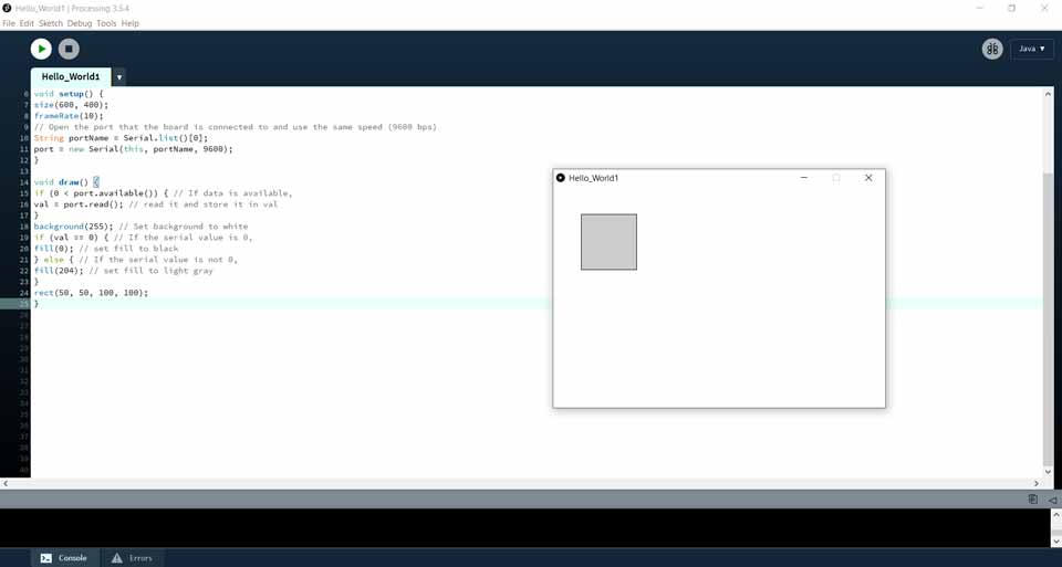
In processing we will take the data from Arduino and analyze what it is sending as a message.
Processing comes with a library which is a serial library.
In Processing go to Sketch Import Library Serial .
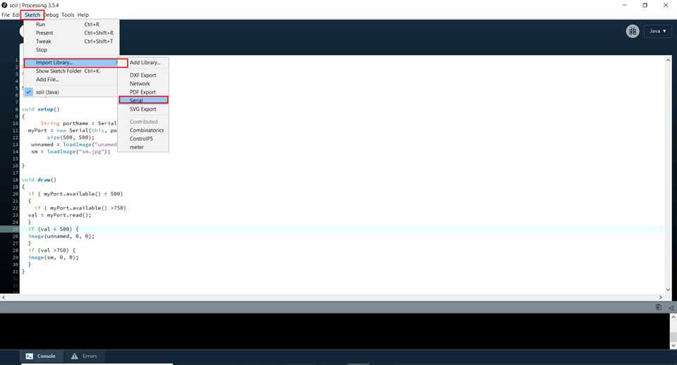
An we will see this message in the sketch: import processing.serial.*;
Then we will need to write some global variables in processing such as: myPort, setup(), loop(), draw() and many others.
Code:
Written by sparkfun
Modified by Ghinwa Azzi Fab Academy 2021
import processing.serial.*;

Serial port; // Create object from Serial class
int val; // Data received from the serial port

void setup() {
size(600, 400);
frameRate(10);
// Open the port that the board is connected to and use the same speed (9600 bps)
String portName = Serial.list()[0];
port = new Serial(this, portName, 9600);
}

void draw() {
if (0 < port.available()) { // If data is available,
val = port.read(); // read it and store it in val
}
background(255); // Set background to white
if (val == 0) { // If the serial value is 0,
fill(0); // set fill to black
} else { // If the serial value is not 0,
fill(204); // set fill to light gray
}
rect(50, 50, 100, 100);
}
The code is from sparkfun page modified by Ghinwa Azzi for the Fab Academy 2021 exercise learning process.
First Exercise:
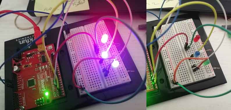
To learn how everything works I decided to do a basic exercise controlling several LEDs with an Arduino IDE and Processing Softwares.
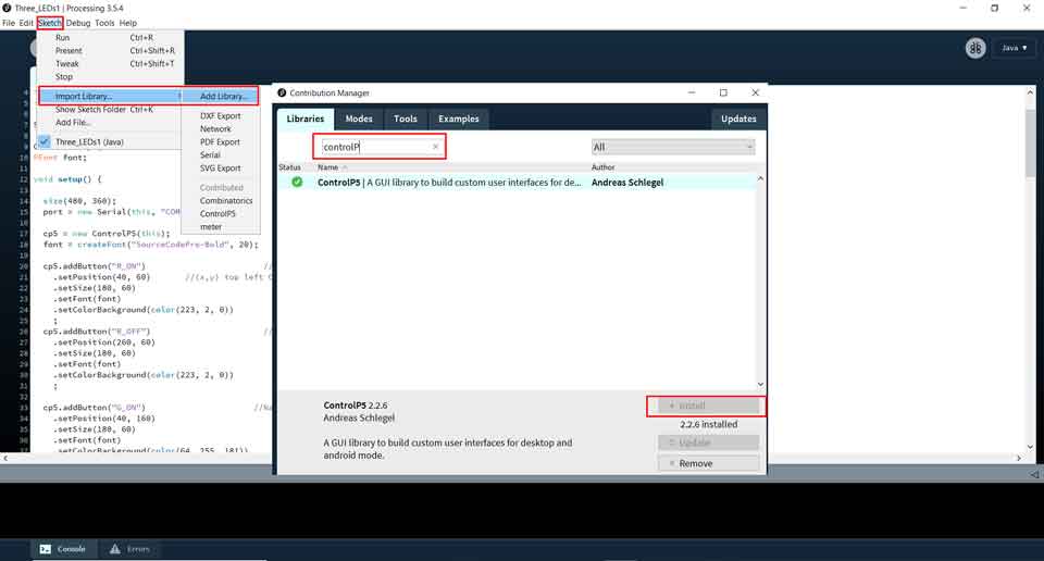
In this exercise I had to download an extra library from sketch-import library-add library and in the panel search for ControlP5 and install it.
ControlP5 offers a range of controllers that allow you to easily change and adjust values while your sketch is running. Each controller is identified by a unique name assigned when creating a controller. ControlP5 locates variables and functions inside your sketch and will link controllers to matching variables or functions automatically.
In the Arduino code I added three LEDs each connected to a PIN: blue connected to PIN4, green connected to PIN3, and red connected to PIN4 with each having a different variable assigned to it.
Code:
Written by sdev
Modified by Ghinwa Azzi Fab Academy 2021
#define led1 4    //red
#define led2 3    //green
#define led3 2    //blue

void setup() {
  Serial.begin(9600);
  pinMode(led1, OUTPUT);
  pinMode(led2, OUTPUT);
  pinMode(led3, OUTPUT);
}

void loop() {
  if (Serial.available()) {
    char val = Serial.read();
    if (val == 'R') {
      digitalWrite(led1, HIGH);
    }
    if (val == 'r') {
      digitalWrite(led1, LOW);
    }
    if (val == 'G') {
      digitalWrite(led2, HIGH);
    }
    if (val == 'g') {
      digitalWrite(led2, LOW);
    }
    if (val == 'B') {
      digitalWrite(led3, HIGH);
    }
    if (val == 'b') {
      digitalWrite(led3, LOW);
    }
  }
}
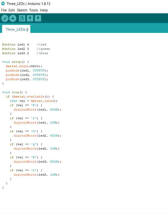
Then I uploaded the code.
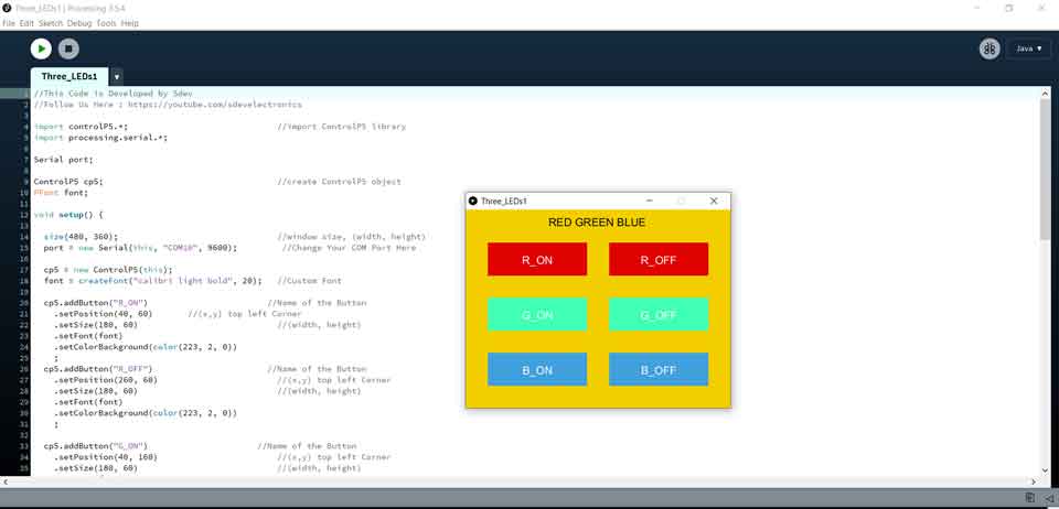
After checking that the Arduino code is working I started writing the code in processing.
I decided in Processing to create a control panel for each LED to turn ON and OFF.
Code:
Written by sdev
Modified by Ghinwa Azzi Fab Academy 2021
import controlP5.*;
import processing.serial.*;

Serial port;

ControlP5 cp5;
PFont font;

void setup() {

  size(480, 360);
  port = new Serial(this, "COM10", 9600);
  cp5 = new ControlP5(this);
  font = createFont("SourceCodePro-Bold", 20);

  cp5.addButton("R_ON")
    setPosition(40, 60)
    setSize(180, 60)
    setFont(font)
    setColorBackground(color(223, 2, 0))
    ;
  cp5.addButton("R_OFF")
    setPosition(260, 60)
    setSize(180, 60)
    setFont(font)
    setColorBackground(color(223, 2, 0))
    ;

  cp5.addButton("G_ON")
    setPosition(40, 160)
    setSize(180, 60)
    setFont(font)
    setColorBackground(color(64, 255, 181))
    ;
  cp5.addButton("G_OFF")
    setPosition(260, 160)
    setSize(180, 60)
    setFont(font)
    setColorBackground(color(64, 255, 181))
    ;

  cp5.addButton("B_ON")
    setPosition(40, 260)
    setSize(180, 60)
    setFont(font)
    setColorBackground(color(64, 160, 221))
    ;
  cp5.addButton("B_OFF")
    setPosition(260, 260)
    setSize(180, 60)
    setFont(font)
    setColorBackground(color(64, 160, 221))
    ;
}
void draw() {

  background(243, 206, 0);
  //Title
  fill(0, 0, 0);
  textFont(font);
  text("RED GREEN BLUE", 150, 30);
}

void R_ON() {
  port.write('R');
}

void G_ON() {
  port.write('G');
}

void B_ON() {
  port.write('B');
}

void R_OFF() {
  port.write('r');
}

void G_OFF() {
  port.write('g');
}

void B_OFF() {
  port.write('b');
}
This code is developed by Sdev and modified by Ghinwa Azzi Fab Academy 2021. I changed the pin number and all the readigns with the colors and text.
As we can see in the above code each LED has an assigned group of commands with a different tab that has ON and OFF, color and position.
Second Exercise:
In the second exercise I decided to connect the soil humidity sensor write two codes in Arduino and Processing then create some visuals for the values obtained.
First I started by writing the code in Arduino determining the min and max values.
soilWet 750 // Define max value we consider soil 'wet'
soilDry 500 // Define min value we consider soil 'dry'
Connected to the analog pin A0 with VCC and GND.
Code:
Written by lastminuteengineer
Modified by Ghinwa Azzi Fab Academy 2021
/* Change these values based on your calibration values */
#define soilWet 750   // Define max value we consider soil 'wet'
#define soilDry 500   // Define min value we consider soil 'dry'

// Sensor pins
#define sensorPower 5
#define sensorPin A2

void setup() {
  pinMode(sensorPower, OUTPUT);

  // Initially keep the sensor OFF
  digitalWrite(sensorPower, LOW);

  Serial.begin(9600);
}

void loop() {
  //get the reading from the function below and print it
  int moisture = readSensor();
  Serial.print("Analog Output: ");
  Serial.println(moisture);

  // Determine status of our soil
  if (moisture > soilWet) {
    Serial.println("Status: Wet Soil");
  } else if (moisture >= soilWet && moisture < soilDry) {
    Serial.println("Status: Perfect Soil");
  } else {
    Serial.println("Status: Dry Soil");
  }

  delay(2000);  // Take a reading every second for testing
          // Normally you should take reading perhaps once or twice a day
  Serial.println();
}

//  This function returns the analog soil moisture measurement
int readSensor() {
  digitalWrite(sensorPower, HIGH);  // Turn the sensor ON
  delay(10);              // Allow power to settle
  int val = analogRead(sensorPin);  // Read the analog value form sensor
  digitalWrite(sensorPower, LOW);   // Turn the sensor OFF
  return val;             // Return analog moisture value
}
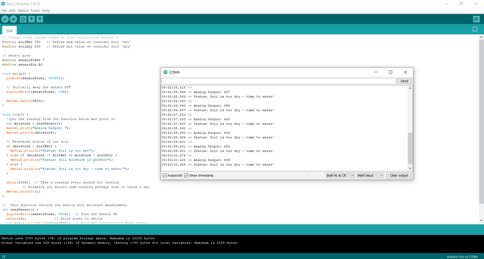
Then I uploaded the code and checked the values on the serial monitor.
After checking that the Arduino code is working I started writing the code in processing.
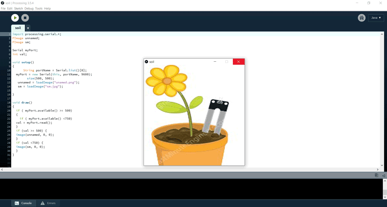
I decided to add two images that will show when the soil is dry with water drops determing that it needs watering and when it is wet without water drops.
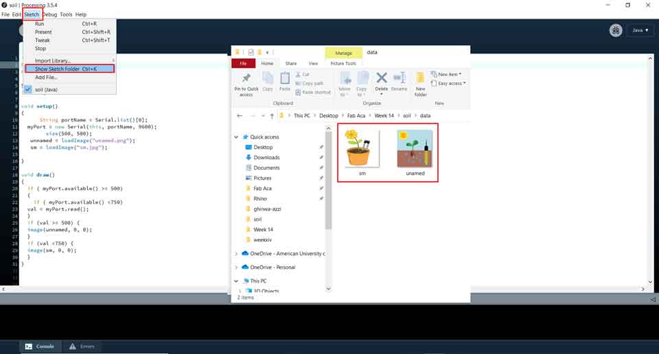
To include images to the processing file we have to include them in the same local folder were the code is.
Sketch then show sketch folder here we will select the folder were the images are found.
This will change according to the values read from the sensor.
Code:
by Ghinwa Azzi Fab Academy 2021
import processing.serial.*;
PImage unnamed;
PImage sm;

Serial myPort;
int val;

void setup()
{
      String portName = Serial.list()[0];
  myPort = new Serial(this, portName, 9600);
        size(500, 500);
   unnamed = loadImage("unamed.png");
   sm = loadImage("sm.jpg");

}

void draw()
{
  if ( myPort.available() >= 500)
  {
    if ( myPort.available() <750)
  val = myPort.read();
  }
  if (val >= 500) {
  image(unnamed, 0, 0);
  }
  if (val <750) {
  image(sm, 0, 0);
  }
The above arduino code is from lastminuteengineer page and I did some modifications to it. As for the processing code I wrote it according to the values in the arduino code.
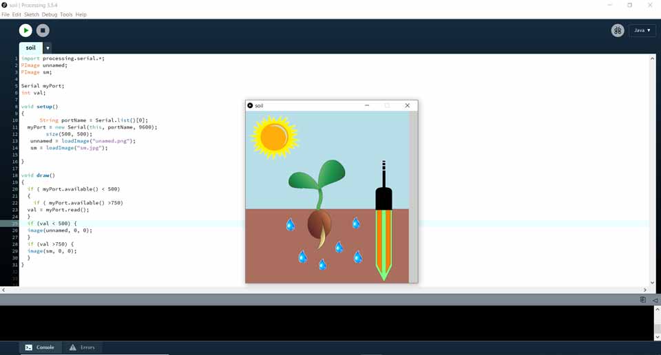
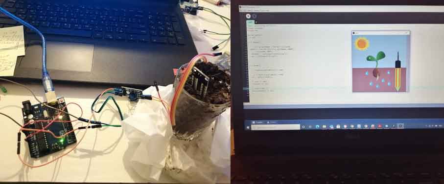
In this case the soil was dry so the image with water drops appeared indicating that the plants need to be watered.
Third Exercise:
In the third exercise I decided to connect the water level sensor write two codes in Arduino and Processing then create some visuals for the values obtained.
Also like previously first I started by writing the code in Arduino determining the min and max values.
Water level: SENSOR_MIN 0
Water level: SENSOR_MAX 521
Connected to the analog pin A0 with VCC and GND.
Code:
Written by arduino
Modified by Ghinwa Azzi Fab Academy 2021
#define POWER_PIN  7
#define SIGNAL_PIN A0
#define SENSOR_MIN 0
#define SENSOR_MAX 521

int value = 0; // variable to store the sensor value
int level = 0; // variable to store the water level

void setup() {
  Serial.begin(9600);
  pinMode(POWER_PIN, OUTPUT);   // configure D7 pin as an OUTPUT
  digitalWrite(POWER_PIN, LOW); // turn the sensor OFF
}

void loop() {
  digitalWrite(POWER_PIN, HIGH);  // turn the sensor ON
  delay(10);                      // wait 10 milliseconds
  value = analogRead(SIGNAL_PIN); // read the analog value from sensor
  digitalWrite(POWER_PIN, LOW);   // turn the sensor OFF

  level = map(value, SENSOR_MIN, SENSOR_MAX, 0, 521); // 4 levels
  Serial.print("Water level: ");
  Serial.println(level);

  delay(1000);
}
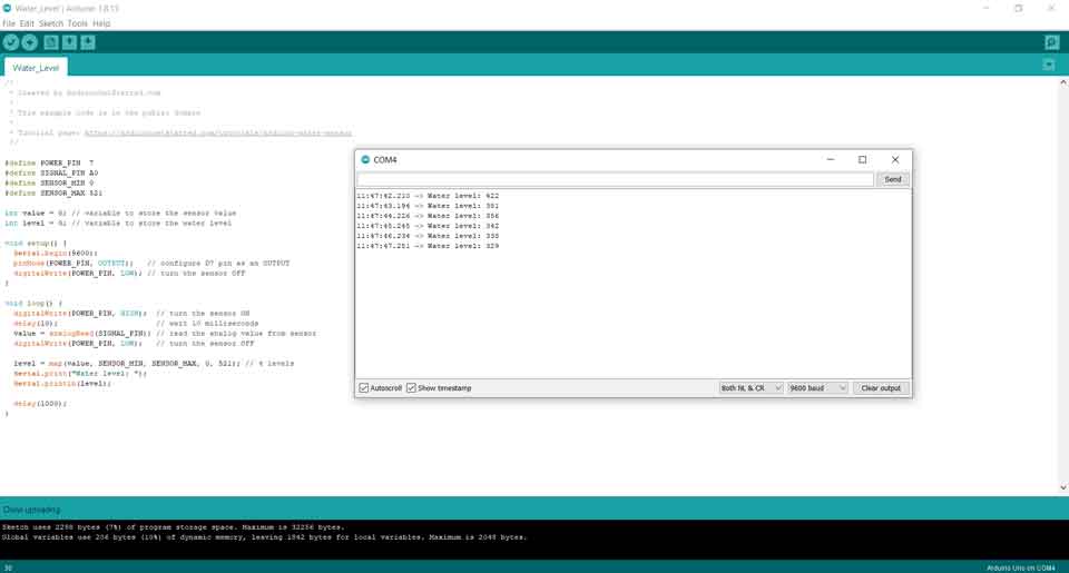
Then I uploaded the code and checked the values on the serial monitor.
After checking that the Arduino code is working I started writing the code in processing.
This time I decided to add text with different colored backgrounds that will change according to the data received from the Arduino code.
While writing the code I started changing and trying different text size, background colors, postion of the text x and y ...
Code:
by Ghinwa Azzi Fab Academy 2021
import processing.serial.*;
size(500, 500);

fill(0, 140); // Fill black with low opacity
float min  = 0;
float med = 250;
float max = 521;

if (max >500) {
  textSize(20);
  background(0, 218, 210);
  text("Keep Pump OFF", 70, 100);
  textSize(40);
  text("Water Level High!", 70, 155);
}
else if (med  >= 250) {
  textSize(20);
  background(255, 0, 0);
   text("Water Level Medium!", 70, 140);
    textSize(40);
  text("Keep Pump OFF", 70, 195);

}
else if (min  <150) {
  textSize(20);
  background(0, 255, 0);
  text("Water Level Low!", 90, 120);
  textSize(40);
  text("Turn Pump ON", 90, 175);
}
In the above code I determined the min, med and max values.
max >500 will tell us that the water level is high so it will keep the pump OFF
med >=250 will tell us that the water level is medium so it will also keep the pump OFF
min <150 will tell us that the water level is low so it will turn the pump ON
The above arduino code is from te arduino page and I did some modifications to it. As for the processing code I wrote it according to the values in the arduino code.
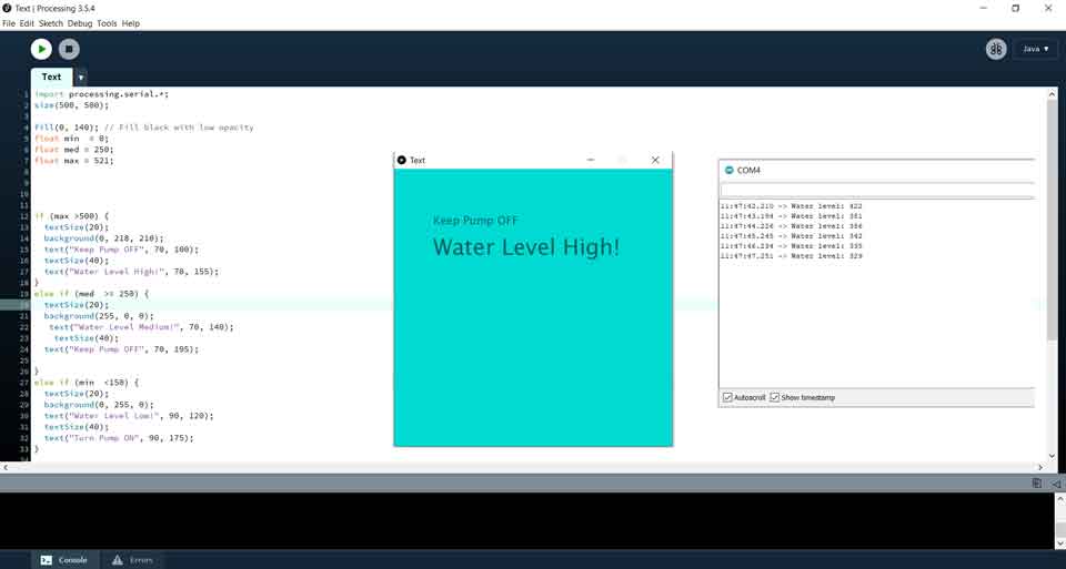
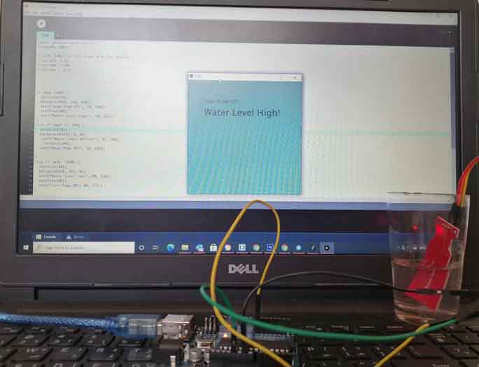
In the above example the water level was above 330 so it was determined as water level high, keep pump OFF.
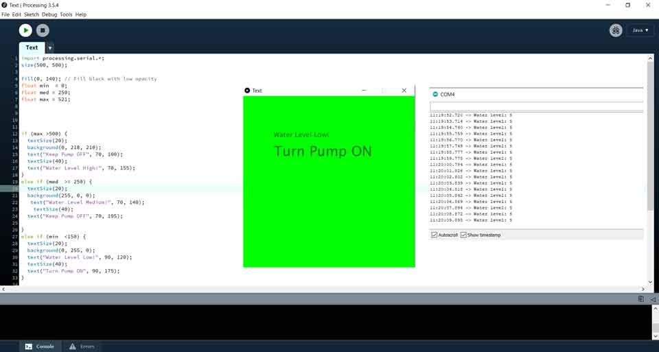
In the above example the water level was below 150 so it was determined as water level low, turn pump ON.
Fourth Exercise:
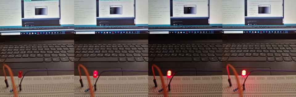
In the fourth exercise I decided to connect potentiometer with a green LED write two codes in Arduino and Processing then create some visuals for the values obtained.
Also like previously first I started by writing the code in Arduino. In the below code:
The LED will go from 0 to 5V (Low and High)
The potentiometer will go from min 0 up to max 1023
As we turn the knob it will decrease and increase.
Connected to the analog pin A0 with VCC and GND.
Code:
Written by arduino
Modified by Ghinwa Azzi Fab Academy 2021
int led_pin = 13;    // Initializing the LED pin

int pot_pin = A0;   // Initializing the Potentiometer pin

int pot_output;     // Declaring a variable for potentiometer output


void setup ( ) {

pinMode(led_pin, OUTPUT); // Declaring the LED pin as output pin

Serial.begin(9600);       // Starting the serial communication at 9600 baud rate

}

void loop ( ) {

pot_output = analogRead (pot_pin); // Reading from the potentiometer

int mapped_output = map (pot_output, 0, 1023, 0, 255); // Mapping the output of potentiometer to 0-255 to be read by the Processing IDE

Serial.println (mapped_output);     // Sending the output to Processing IDE


if (Serial.available ( ) > 0) {   // Checking if the Processing IDE has send a value or not

char state = Serial.read ( );    // Reading the data received and saving in the state variable

if(state == '1')             // If received data is '1', then turn on LED

{

digitalWrite (led_pin, HIGH);

}

if (state == '0') {     // If received data is '0', then turn off led

digitalWrite (led_pin, LOW);

}

}

delay(50);

}
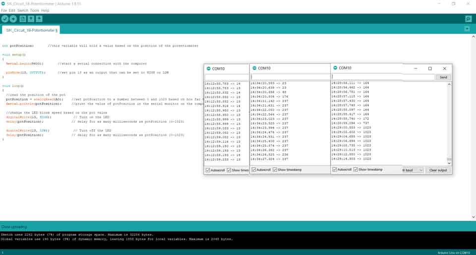
Then I uploaded the code and checked the values on the serial monitor.
As we can see in the above serial monitor the different values changing as I turn the knob.
After checking that the Arduino code is working I started writing the code in processing.
As I turn the knob of the potentiometer the background color will change as the value decreases and increases and the led will turn ON and OFF as I click the left and right buttons of the mouse.
While writing the code I started changing by inserting the window size that will appear on the screen and the commands for the mouse right and left.
Code:
Written by arduino
Modified by Ghinwa Azzi Fab Academy 2021
import processing.serial.*;    // Importing the serial library to communicate with the Arduino

Serial myPort;      // Initializing a vairable named 'myPort' for serial communication

float background_color ;   // Variable for changing the background color


void setup ( ) {

size (300,  300);     // Size of the serial window, you can increase or decrease as you want

myPort  =  new Serial (this, "COM10",  9600); // Set the com port and the baud rate according to the Arduino IDE

myPort.bufferUntil ( '\n' );   // Receiving the data from the Arduino IDE

}

void serialEvent  (Serial myPort) {

background_color  =  float (myPort.readStringUntil ( '\n' ) ) ;  // Changing the background color according to received data

}

void draw ( ) {

background ( 100, 150, background_color );   // Initial background color, when we will open the serial window

if ( mousePressed  &&  ( mouseButton  ==  LEFT ) ) { // if the left mouse button is pressed

myPort.write ( '2' ) ;       // send a '1' to the Arduino IDE

}

if  ( mousePressed  &&  ( mouseButton == RIGHT ) ) {  // if the right mouse button is pressed

myPort.write ( '3' ) ;     // Send a '0' to the Arduino IDE

}

}
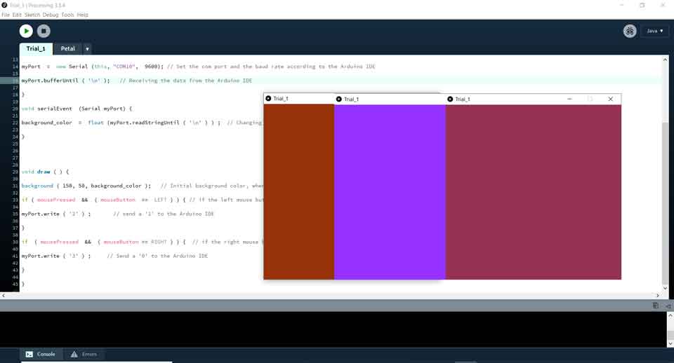
Above is an example of the different colors that changed with the poteniometer was changing values.
Group Assignment
Here you can find our group assignment LINK
Interface and Application Programming
So the objective of this week is to get introduced to using Code to Create Applications that Interface with input and output devices.
According to Wikipidia, "In computer programming, an application programming interface (API) is a set of subroutine definitions, protocols, and tools for building application software.
In general terms, it is a set of clearly defined methods of communication between various software components.
A good API makes it easier to develop a computer program by providing all the building blocks, which are then put together by the programmer.
An API may be for a web-based system, operating system, database system, computer hardware or software library.
An API specification can take many forms, but often includes specifications for routines, data structures, object classes, variables or remote calls.
POSIX, Windows API and ASPI are examples of different forms of APIs. Documentation for the API is usually provided to facilitate usage and reimplementation.
There are many languages that could be used to build applications that interface with Input and Output devices.
Out of which are C++, JAVA, Python, Arduino, and Processing. In this section, we will learn on how to collect data from sensors through a microcontroller, and how to use coding to Simulate and Visualize the measurements in Graphical representations.
The group assginment was to Compare as many tool options as possible.
Test 1 - Dimming LED with processing:
We will use Processing to control the brightness of the LED according the movement of the mouse.
Arduino Code:
const int ledPin = 9;      // the pin that the LED is attached to

void setup() {

  // initialize the serial communication:

  Serial.begin(9600);

  // initialize the ledPin as an output:

  pinMode(ledPin, OUTPUT);
}

void loop() {

  byte brightness;

  // check if data has been sent from the computer:

  if (Serial.available()) {

    // read the most recent byte (which will be from 0 to 255):

    brightness = Serial.read();

    // set the brightness of the LED:

    analogWrite(ledPin, brightness);

  }
}
Processing Code:
  // Dimmer - sends bytes over a serial port

  // by David A. Mellis

  // This example code is in the public domain.

  import processing.serial.*;

  Serial port;

  void setup() {

    size(256, 150);

    println("Available serial ports:");

    // if using Processing 2.1 or later, use Serial.printArray()

    println(Serial.list());

    // Uses the first port in this list (number 0). Change this to select the port

    // corresponding to your Arduino board. The last parameter (e.g. 9600) is the

    // speed of the communication. It has to correspond to the value passed to

    // Serial.begin() in your Arduino sketch.

    port = new Serial(this, Serial.list()[0], 9600);

    // If you know the name of the port used by the Arduino board, you can specify

    // it directly like this.

    //port = new Serial(this, "COM1", 9600);

  }

  void draw() {

    // draw a gradient from black to white

    for (int i = 0; i < 256; i++) {

      stroke(i);

      line(i, 0, i, 150);

    }

    // write the current X-position of the mouse to the serial port as

    // a single byte

    port.write(mouseX);

  }
Test 2 - Controlling Servo Motor with Grasshopper
As I use Rhinoceros and Grasshopper for parametric designs, I was interested to know how to connect Arduino boards with sensors and motors to read data.
First, I had to download and install FIREFLY plugin which is used to connect grasshopper to micro-controllers linking the digital and physical world.
Firefly WebsiteI wanted to test servo motors with the Arduino code related to servo motors.
Arduino Code:
/*
 Controlling a servo position using a potentiometer (variable resistor)
 by Michal Rinott
 modified on 8 Nov 2013
 by Scott Fitzgerald
 http://www.arduino.cc/en/Tutorial/Knob
*/
#include
Servo myservo;  // create servo object to control a servo
int potpin = 0;  // analog pin used to connect the potentiometer
int val;    // variable to read the value from the analog pin
void setup() {
  myservo.attach(7);  // attaches the servo on pin 9 to the servo object
}
void loop() {
  val = analogRead(potpin);            // reads the value of the potentiometer (value between 0 and 1023)
  val = map(val, 0, 1023, 0, 180);     // scale it to use it with the servo (value between 0 and 180)
  myservo.write(val);                  // sets the servo position according to the scaled value
  delay(15);                           // waits for the servo to get there
}
Grasshopper Data Tree
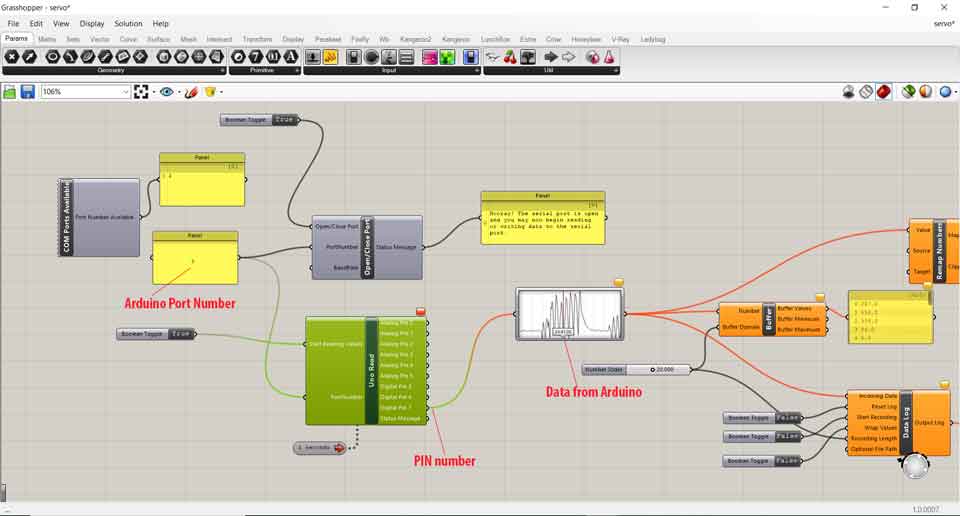
In the Arduino port number, we have to check the COM and change it in the panel.
In PIN number it should be the same as the PIN in the Arduino code that is connected to the servo motor.
Data from Arduino is read once we upload the code.
Test 3 - Blinking LED using Blynk
We used the application Blynk to turn ON and OFF the built in LED with Wi-Fi connection using esp8226.
Blynk Setup:
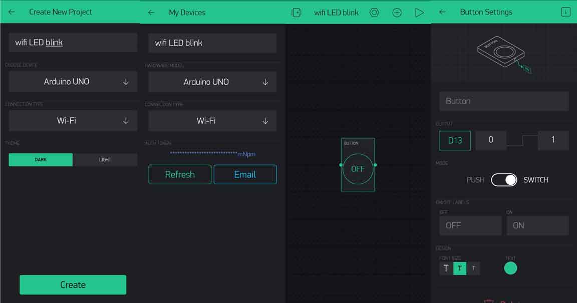
Authentication code will be sent by email, copy the code, since it will be placed in the Arduino Code.
Note that the wifi preferences must be changed according to your router settings.
Arduino Code:
#define BLYNK_PRINT Serial
#include
#include
#include
#define BLYNK_PRINT Serial


#include
#include

// You should get Auth Token in the Blynk App.
// Go to the Project Settings (nut icon).
char auth[] = "FQlB6sMx-4cpKpxt47Qyhuh-qwAH9HPP";

// Your WiFi credentials.
// Set password to "" for open networks.
char ssid[] = "Chaaban";
char pass[] = "330330330";

// Hardware Serial on Mega, Leonardo, Micro...
//#define EspSerial Serial1

// or Software Serial on Uno, Nano...
//#include
SoftwareSerial EspSerial(2, 3); // RX, TX

// Your ESP8266 baud rate:
#define ESP8266_BAUD 38400

ESP8266 wifi(&EspSerial);

void setup()
{
  // Debug console
  Serial.begin(9600);

  // Set ESP8266 baud rate
  EspSerial.begin(ESP8266_BAUD);
  delay(10);

  Blynk.begin(auth, wifi, ssid, pass);
  // You can also specify server:
  //Blynk.begin(auth, wifi, ssid, pass, "blynk-cloud.com", 80);
  //Blynk.begin(auth, wifi, ssid, pass, IPAddress(192,168,1,100), 8080);
}

void loop()
{
  Blynk.run();
  // You can inject your own code or combine it with other sketches.
  // Check other examples on how to communicate with Blynk. Remember
  // to avoid delay() function!
}
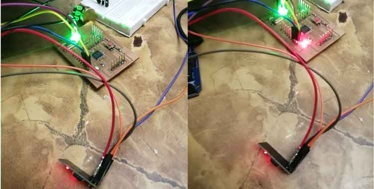
The built-in LED is controlled using the phone via blynk app, when the button is pressed, the LED will be turned ON.
Reference: Youtube Processing Tutorials, Processing Website, Processing Website Tutorials, WIRED, Sparkfun,

This work is licensed under a Creative Commons Attribution-NonCommercial-ShareAlike 4.0 International License