Group Assignment
Characterize the design rules for your PCB production process.
Individual Assignment
Make an in-circuit programmer by milling and stuffing the PCB and test it.
Group Assignment:
Here you can find our group assignment LINK
In this week Electronics Production, we had to make an In-circuit programmer PCB by using a milling machine.
We used copper sheets with two bits 0.4 mm and 1.2 mm as a group we did a test to check paths with different thicknesses using MDX-40 milling machine.
The assignment was divided into two parts:
- Part one of the assignment we prepared the filespart two we learned how to setup the machine and send the file.
- Part two we learned how to setup the machine and send the files.
Machine
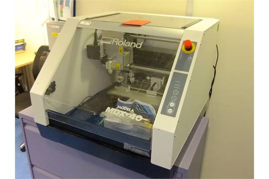
This machine is a subtractive machine technology and it can 2D and 3D Mill.
There are many settings that need to be checked and changed before any milling process that depend on the material and the bit being used. All these settings affect directly the results needed or quality to be achieved.
These settings are:
- Speed (mm/s): it is the rotational speed of the milling tool.
- Feed (mm/s): it is the speed of the milling tool while moving inside the material. In our case we have the copper board while milling the inner lines we used acceptable feed rate but for the outer lines we decreased the feed rates.
Bit diameter: we used 0.4 mm and 1.2 mm milling bits. The smaller the diameter the better details we can achieve. In our case we used 0.4 mm for the inner lines and 1.2 mm for the outer boarder.
Number of offsets: is the number of paths the bit will pass through to remove the material and it is directly related to the final results.
Test file
This test is to check the different paths thicknesses and it was done using the milling bit 0.4 mm.
The code was generated using Fabmodules.
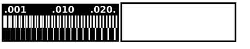
This is the test file the machine will mill all the black areas in the inner lines test and outer border.
Photoshop Editing
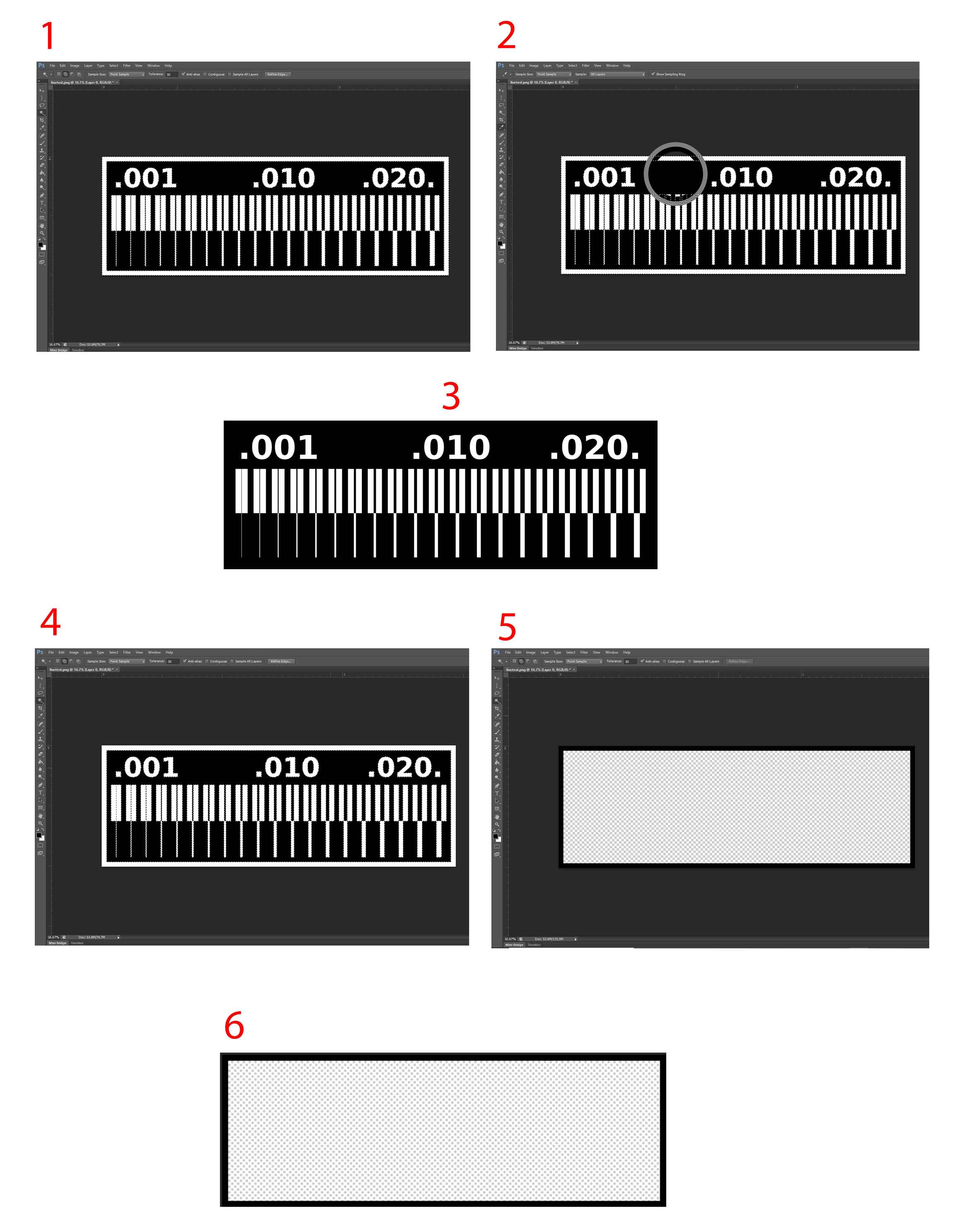
Before sending the file to fab modules, in order to generate the code we had to fix the file on photoshop.
Inner Lines
1- Select using the magic wand tool the white outer boarder.
2- Select the black color using the eyedropper tool and paint the white selection.
3- Save the image as .png
Outer Lines
1- Select the black inner spaces.
2- Delete them.
3- We will only have left the outer rectangle for the outer border.
4- Save the image as .png
Fabmodules
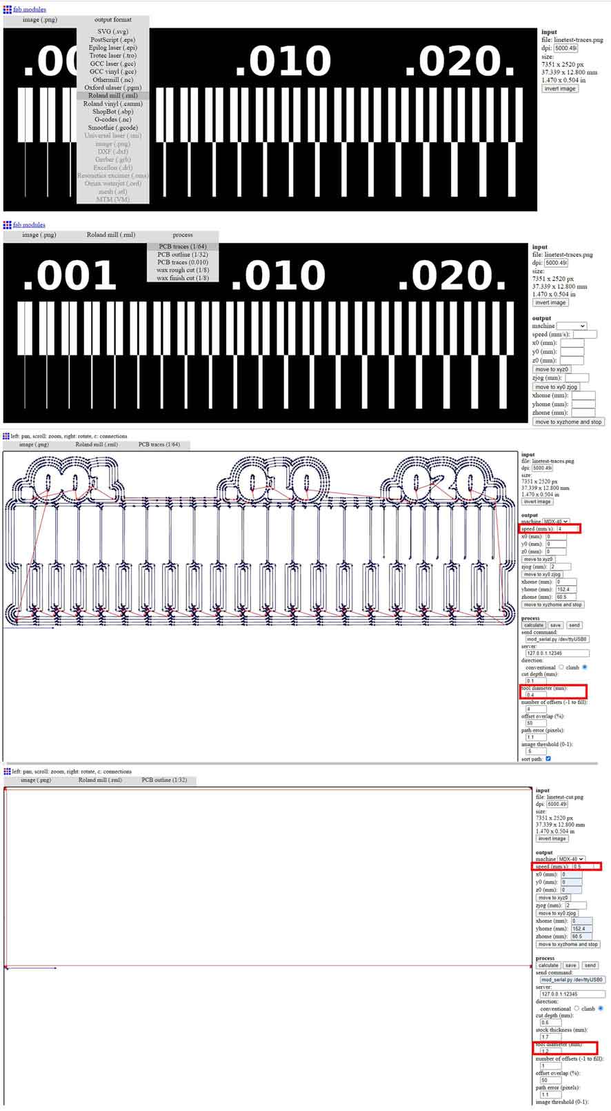
Settings that we changed for the inner lines:
Speed (mm/s) = 4
Tool diameter= 0.4 mm
PCB Traces 1/64
Settings that we changed for the outer lines:
Speed (mm/s) = 0.5
Tool diameter= 1.2 mm
PCB outline= 1/32
Now that we have our files ready as a gcode .rml it is time to go to the machine.
Turn ON the machine by pressing “power” button and wait for it to initialize.
Then press “view” to move the machine to the initial origin.
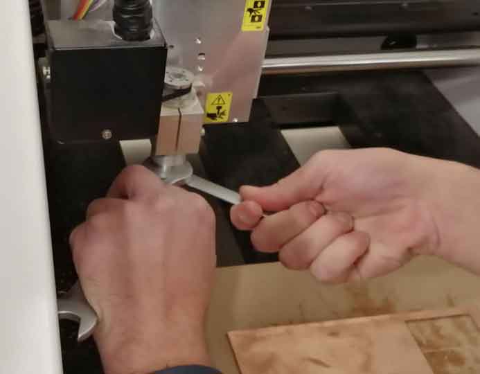
Grab the 0.4mm bit that we will use for the traces and insert it into the collet.
Retract the router bit by 4 mm or so, and then hand-tighten the collet nut to hold the bit in place.
Fully tighten the collet nut with the appropriate wrench.
Using the PC, open the software “DropOut”, at this stage we want to first zero our XY axis from the software, and Z axis from the machines control panel.
Go to “File > Print set up > Properties > Options > Operation panel”.
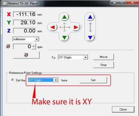
Before moving the XYZ, press “view” on the machine to get it out of the “view” position, now in the operation panel, move the XY axis into your desired starting point, note that the starting point in the generated G-code is bottom-left corner.
Then press set XY origin.
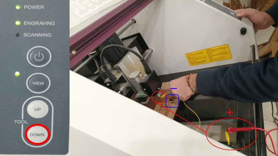
Now we want to zero the Z-axis, to do that, we need a digital multimeter, and an alligator.
Put the digital multimeter in buzzer mode and touch the negative and positive ends together to see if it is buzzing, then attach the alligator to one terminal of the multimeter and attach the other end of the alligator to the router bit.
Now we want to lower the our Z until it touches the copper board, do not forget to touch the free side of the multimeter with the copper board so when the bit touches the copper the multimeter would beep.
Press the down arrow on the machine until it gets close to the board “be careful not to go down too much and break the bit”, then go slowly until the multimeter buzzes, when it does, press the down arrow three little pushes to make sure we have our Z-axis ready.
Now, we go back to the software, and in the properties, we go to tools, and we select the spindle RPM as 10,000.
Then we go to the first window in the software, and we add our traces G-code that we generated previously.
Now that we are ready to start the job, press “Output” on the software, the machine should start milling now, do not open the door of the machine unless there is an emergency.
When the job is done, wait a minute for the machine to stop, then hit “view”, when the XY goes to the corner, open the door, and use the vacuum cleaner to clear the dust.
Now we want to cut our outline, to do so, we need to change the bit following the same previous steps, just make sure the bit does not fall down when removing it.
We used a 1.2mm bit to cut our outline. After putting the new bit, we need to zero the Z-axis again, we will not use the multimeter this time.
Place a paper on the copper board, and carefully move down until the bit touches the paper and makes it hard to move sideways.
Now that we have our new Z position, we will go to the software, delete the old G-code, and add the outline G-code, then press “Output”, the job should now start.
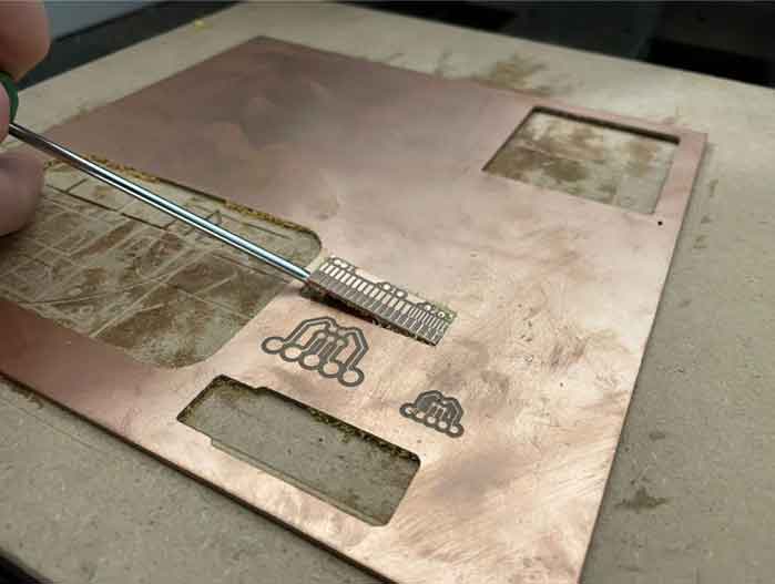
When the job is over, clean the dust, then carefully remove the PCB with by pinching it from the side with a screwdriver. Then, remove the double-sided tape that is on the back of the PCB.
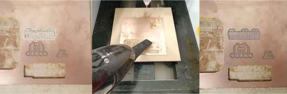
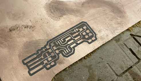
Test Results:
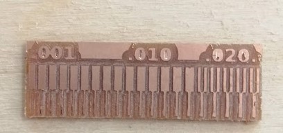
We noticed that not all paths stayed, and the thin paths (less than 0.381mm) were missing. Thus, we deduced that we cannot do traces less than 0.381 mm with our bit.
Individual Assignment:
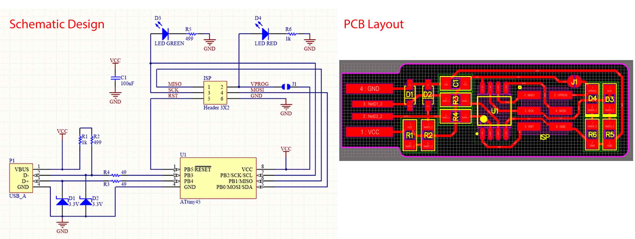
Step 1: Design
I used the BRIAN PCB design.

Usually the schematic design and the ISP board are done on eagle software.
More details of the original documentation: BRIAN
Step 2: PCB Layout
After designing the board, creating the outlines and checking for all the errors and if the board can be manufactured we have to extract the file so we can mill it.
The extracted images each one alone shows all the inner and outer lines of the board connecting all componenets together and it should have monochrome settings.
Before creating a code for milling we should do some edits.
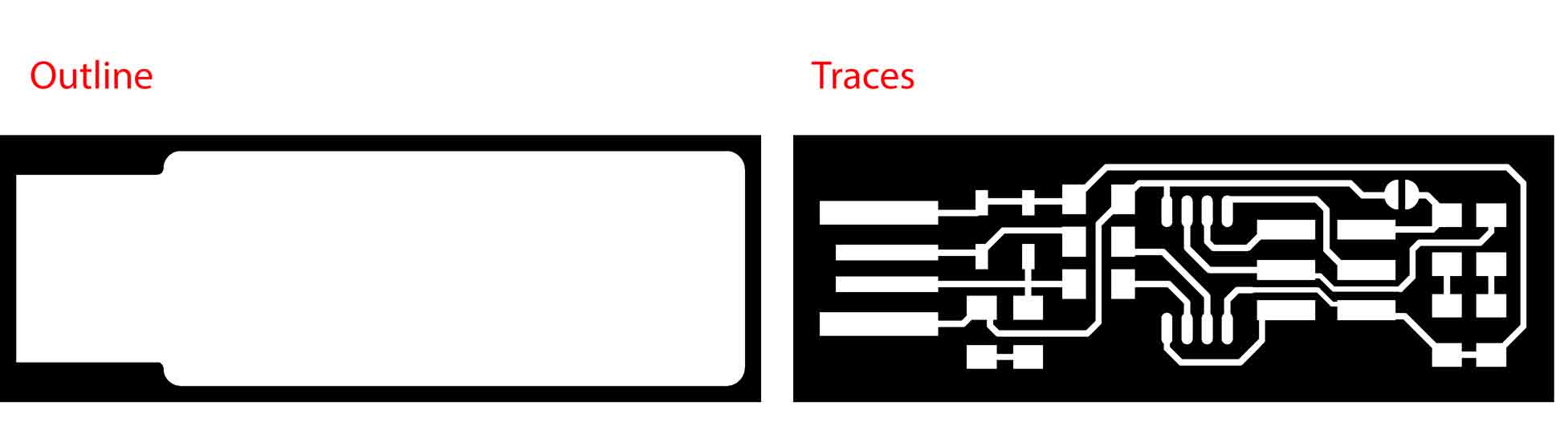
The first image is the outline border of the board and the machine will cut directly through the copper sheet.
The second image is the internal traces the machine will mill all the black areas leaving the white tracks and connectors.
Outline (1000 dpi)
Traces (1000 dpi)
Step 3: G-code
In order to send the file to the milling machine it should be as a gcode format. So we have to transform the images into instructions or paths.
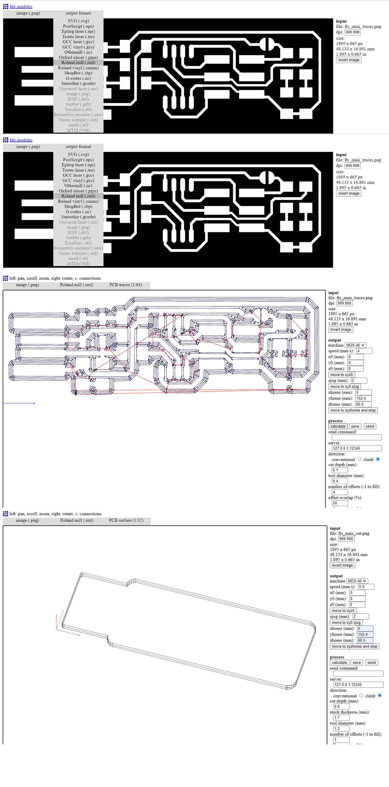
I used Fab Modules to create the paths for the board to be milled.
Below are the steps to create the gcode:
In the image tab select image (.png) and load the file that we want to generate the code from.
In the output format tab select Roland mill (.rml) this is the file format that our machine reads in our case it is Roland MDX-40.
In the process tab we have to choose PCB traces 1/64 for the internal lines and PCB outline 1/32 for the outer cut.
In the right side of Fabmodules we have to plug in the settings we need to use.
Under output choose the machine Roland MDX-40. For the speed we used two different settings 4 mm/s for the internal lines and 0.5 mm/s for the outer cut. X,Y,Z 0 mm.
Under process for the cut depth we choose 0.1 mm for the internal lines the bit we used was 0.4 mm and 1.7 mm diameter for the outline and the bit we used was 1.2 mm diamter.
The number of offsets was 4 and offset overlap 50%.
After checking all the settings we have to calculate the paths and create the gcode.
Finally after checking the previw we can download the code as .rml.
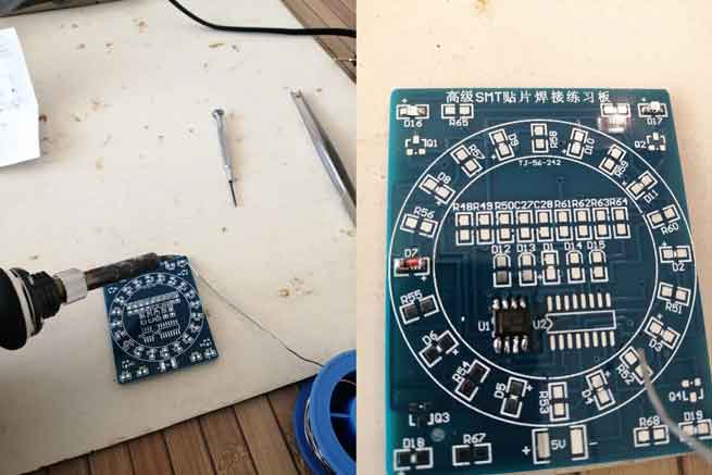
Step 4: Milling Process
- In tis step first we prepared the machine and the copper board using double sided tape to fix the copper into the machine bed.
- In order to send the G-code .rml file to the machine we used drop-out software that is directly connected to the Roland MDX-40 machine.
Below are the steps I followed to send the file to the machine:
- Open Drop out software.
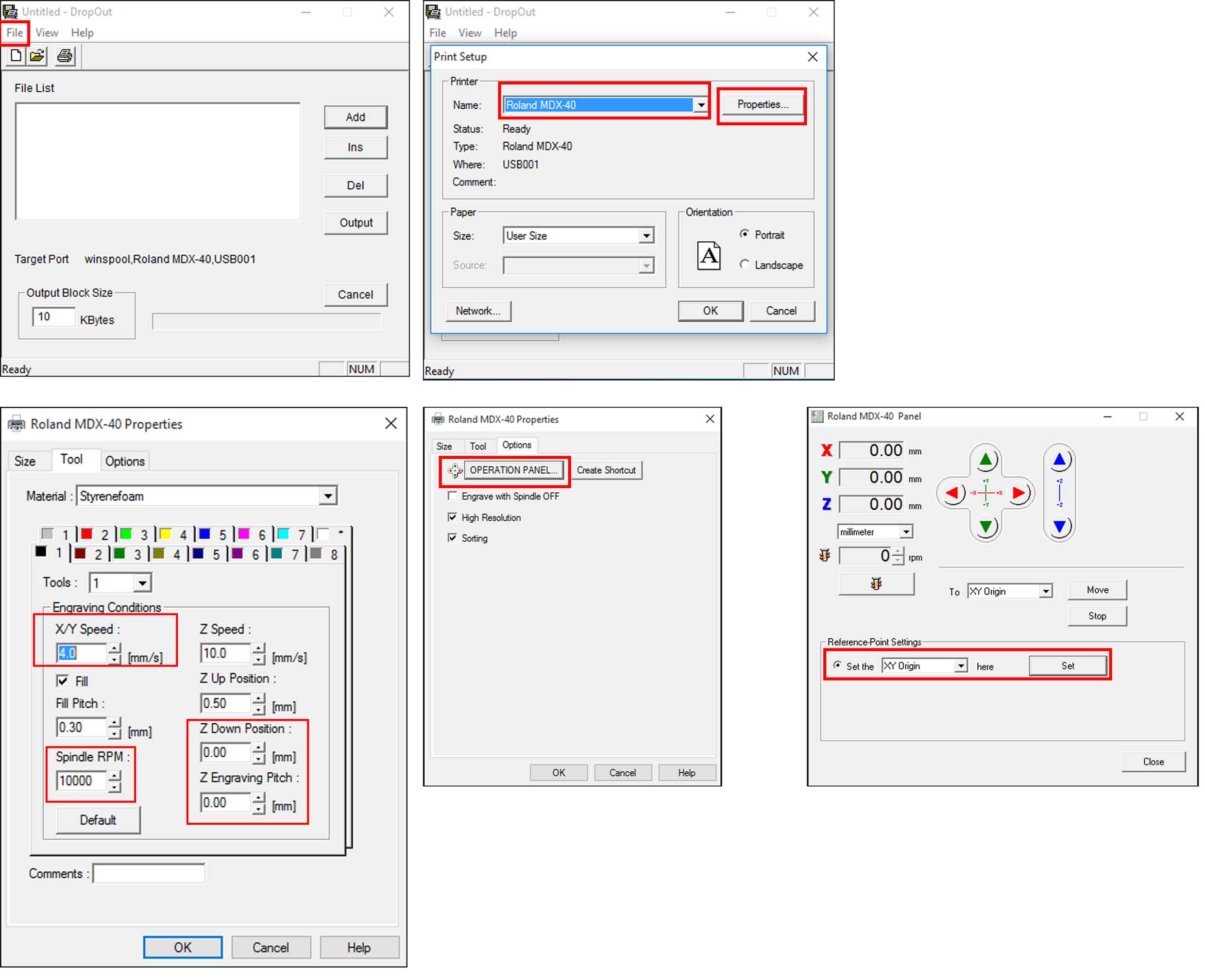
- Click on the file tab then choose print setup.
- A new window opens here we have to choose the printer name we want to use for milling. Our machine is Roland MDX-40.
- In the same window on the right side we have properties in which we have to select to set other settings.
- In the tool tab section engraving conditions the X/Y speed should be 4 mm/s as per the G-code settings and the spindle RPM 10000.
- We also need to chane the Z position (Down and engraving pitch) both are set to 0.00 mm.
- In the same window click on the options tab and operation panel.
- A new panel appears here we have to adjust the X/Y positions according to the copper board. This will locate the position of the PCB to be engraved.
- After locating th X/Y in the reference point settings section we choose XY origin and click set.
- Locating the Z position is a different process and should be done slowly so that we don't break the bit.
- The bit should touch the upper surface of the copper board in this process we used the multimeter one of the cables touching the bit and another on the copper. When we hear the multimeterbeeping it means that the bit is touching the copper and we can set the Z postion in drop out to 0.
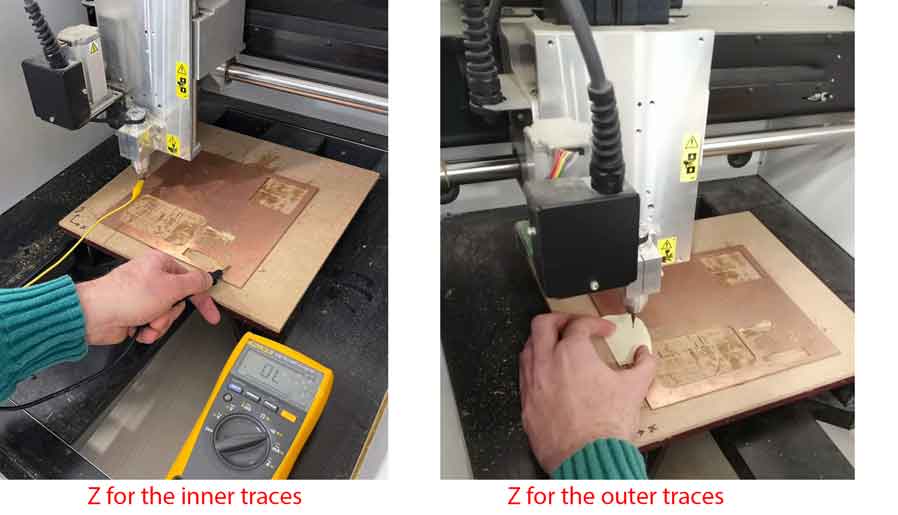
- To load the file .rml click add and select the G-code first for the innr traces and second for the outer lines.
- For the outer lines while setting the Z we did not use the multimeter only a paper thickness for calibrating and the X/Y positions will remain the same.
- Back to the tools tab we only changed the Z down position to -1.7 mm and the X/Y speed to 0.5 mm/s as per the G-code.
- Then we have to delete and load the outer lines .rml file and send for cutting.
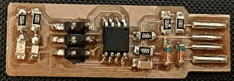
Step 5: Soldering
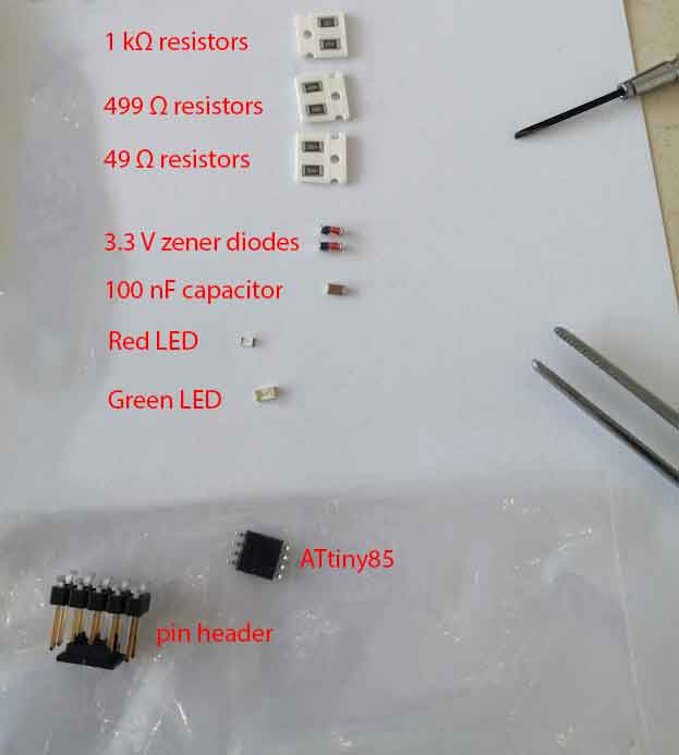
The components needed are:
Resistors: (2) 1 kΩ, (2) 499 Ω and (2) 49 Ω
(2) 3.3 V zener diodes
100 nF capacitor
2x3 pin header
LED red and green
ATtiny45 or ATtiny85
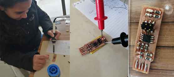
Before soldering the components I practiced on a soldering kit for beginners.
I had to check the orientation of each component alone before soldering it to the board:
Zener diodes are marked with a stripe on one side to indicate polarity. The stripe is on the negative side known as cathode.
ATtiny85 has a dot on pin 1 GND to show the correct orientation also it can be seen in the PCB layout.
The green and red LED have a thick line to indicate the polarity. This thick line can be seen in the PCB layout to show the negative side.
Step 6: Programming
After soldering all the components in the right direction in this step we will do the programming for the microcontroller, we will download the software on the ISP.
1- Download and open Arduino.
2- Check the correct port (tools-port).
3- For the board select Arduino UNO (tools-board).
4- Connect Arduino programmer to the pc and in file-examples open ArduinoISP and upload the sketch.
5- Connect the Arduino to the ISP:
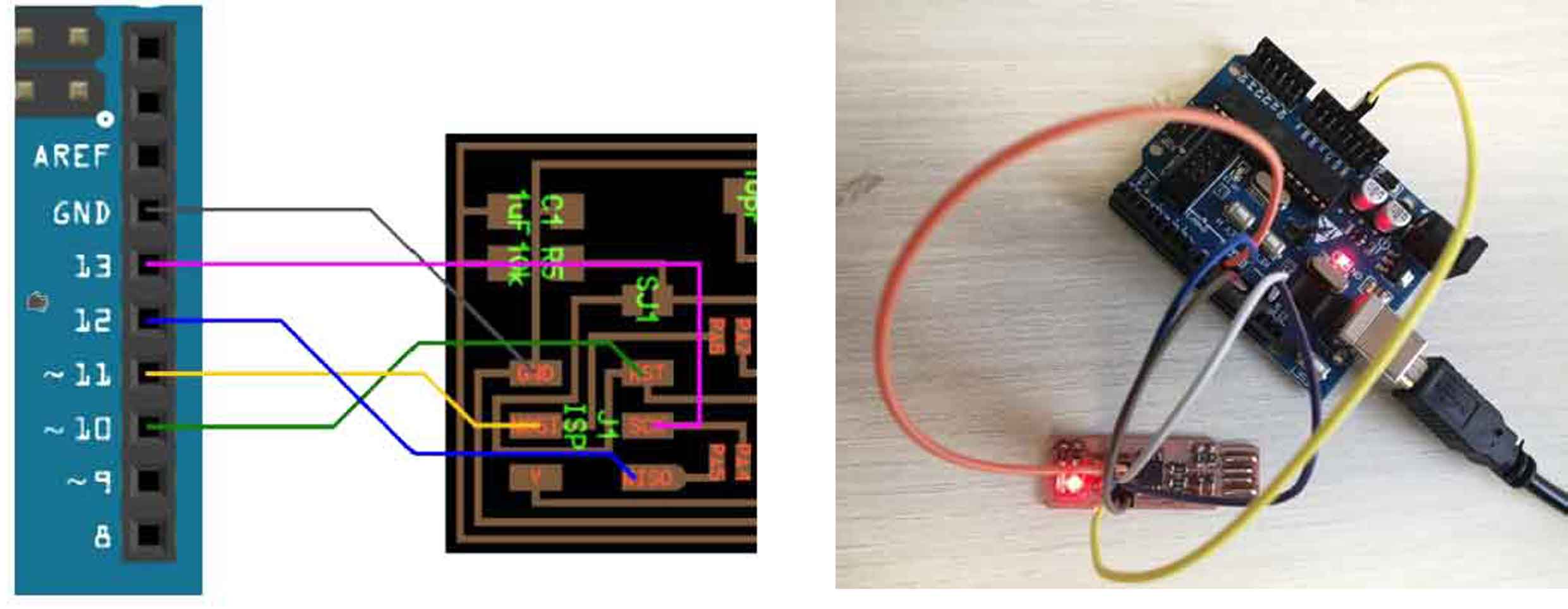
6- Download and extract the firmware .
7- Enter the unzipped file using the linux terminal and go to the code directory.
8- Enter the below commands to generate a make file:
make clean
make
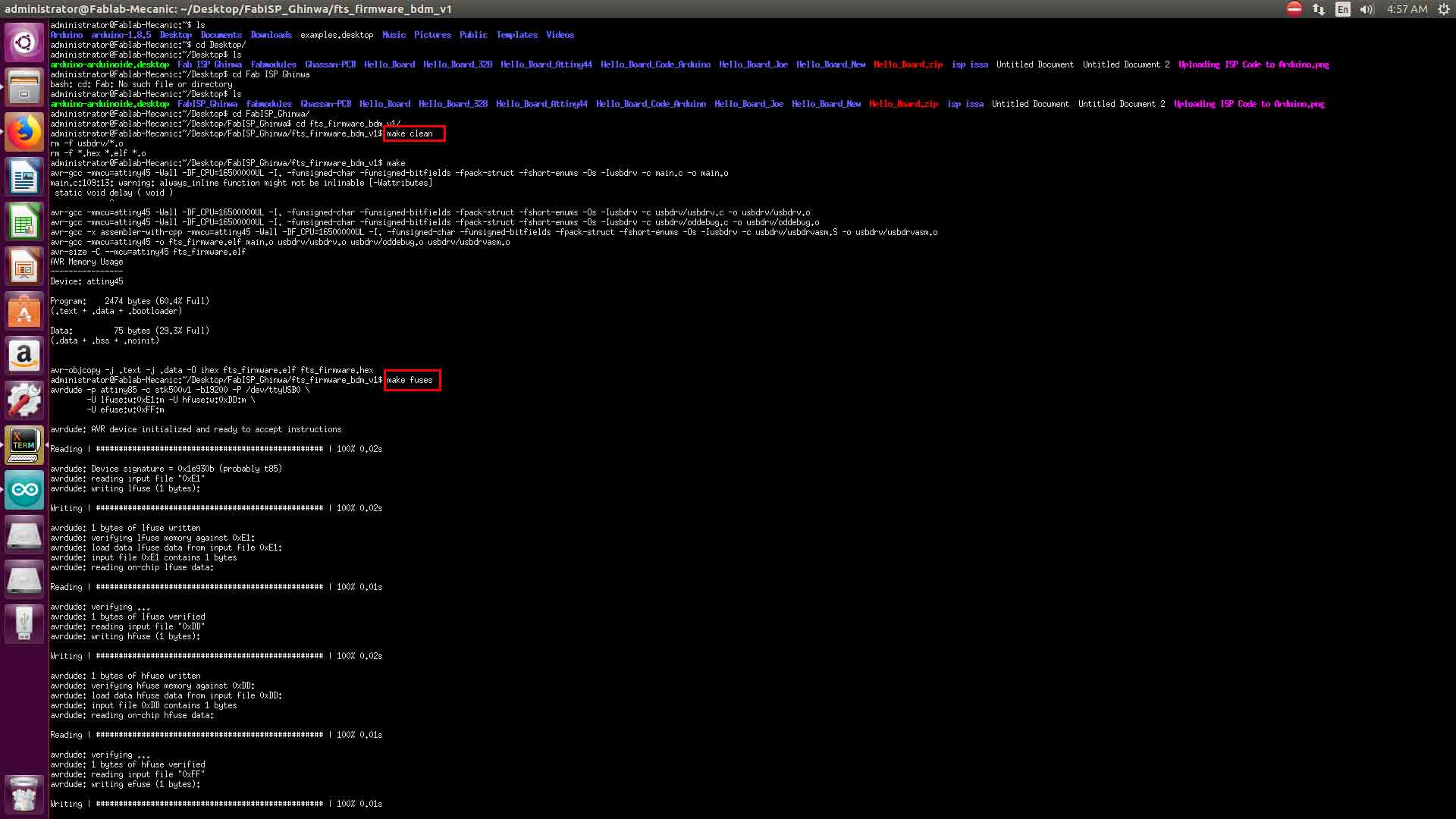
9- Replace the old make file with the new modified Make File .
10- In the Make file we replaced MCU=attiny45 with MCU=attiny85 using a text editor and save the file.
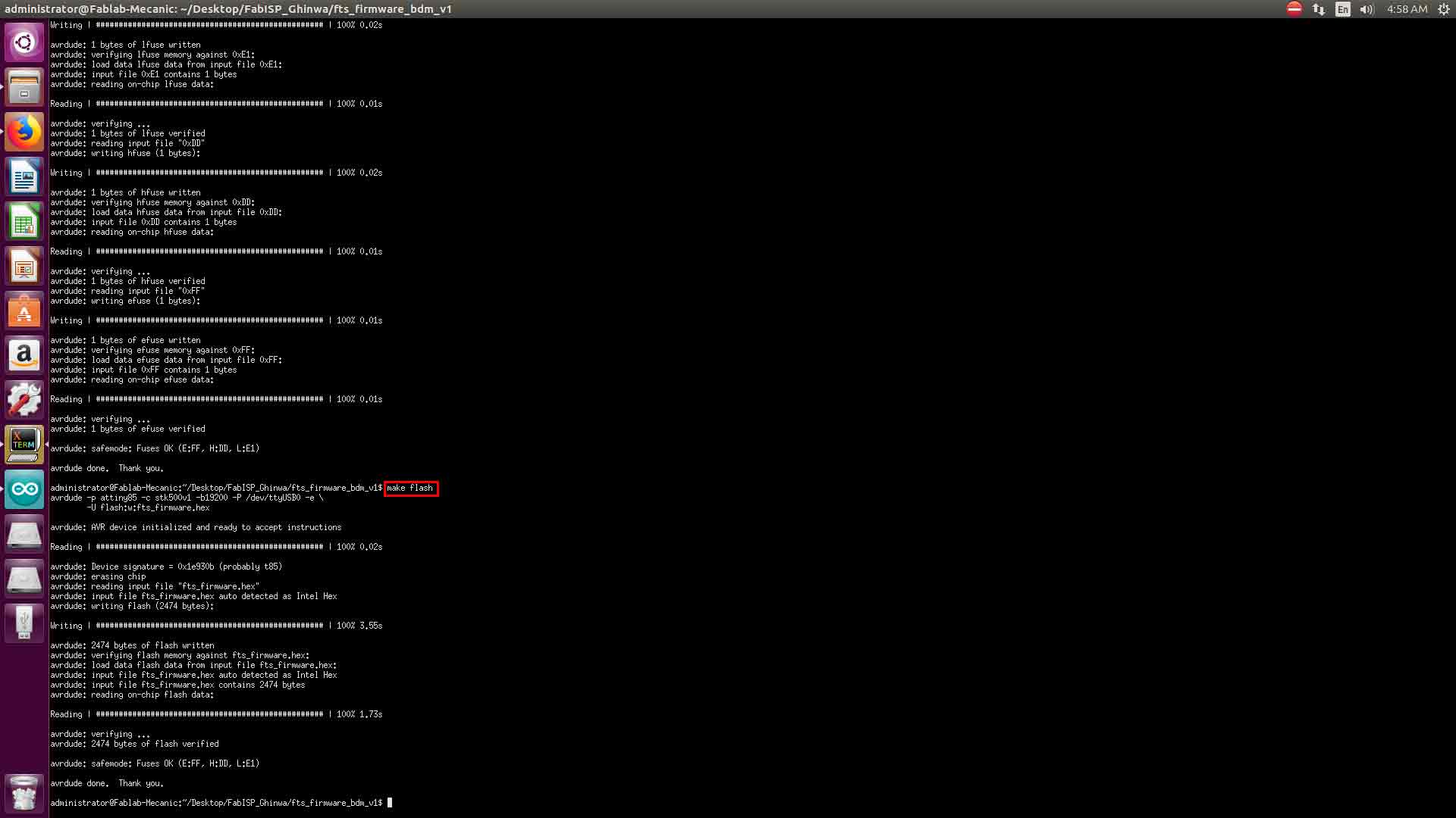
11- To load the programme into the ISP we did the below two commands:
make fuses
make flash
12- Disconnect the ISP from the Arduino and plug it in the PC.
13- After plugging the ISP into the PC it should appear as a USB.
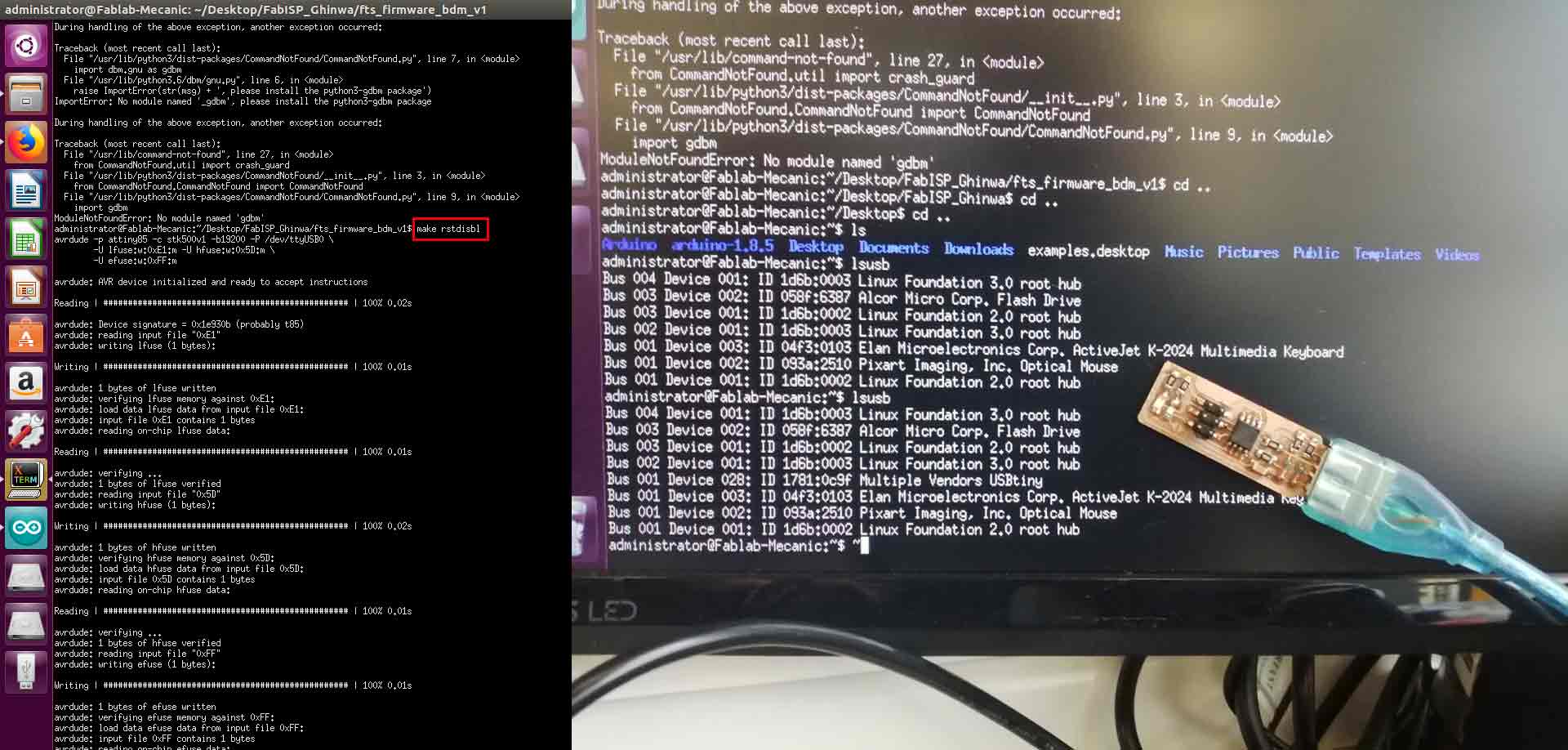
14- The final step after checking the my ISP is recognized is to use the command "rstdisbl" this does the same as make fuses command in addition to the reset disable bit.
I used my FabISP again in the Embedded Programming Week:

This work is licensed under a Creative Commons Attribution-NonCommercial-ShareAlike 4.0 International License